Instruction Manual
Page 3
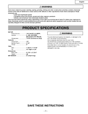
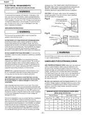
..., replace power cord immediately if it is wired at the factory for your exposure to these chemicals, work in any way. Your Drill Press is worn, cut or damaged in a well-ventilated area and work . Some examples of work with approved safety equipment such as ...filter out microscopic particles. Use a separate electrical circuit for 115V operation. English WARNING Some dust created by power sanding, sawing, grinding, drilling and other construction activities contains chemicals known to the state of California to cause cancer, birth defects or other masonry products • Arsenic...
..., replace power cord immediately if it is wired at the factory for your exposure to these chemicals, work in any way. Your Drill Press is worn, cut or damaged in a well-ventilated area and work . Some examples of work with approved safety equipment such as ...filter out microscopic particles. Use a separate electrical circuit for 115V operation. English WARNING Some dust created by power sanding, sawing, grinding, drilling and other construction activities contains chemicals known to the state of California to cause cancer, birth defects or other masonry products • Arsenic...
Instruction Manual
Page 4
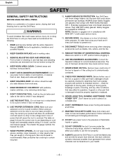
... to determine that it will do the job better and safer at HITACHI. REDUCE THE RISK OF UNINTENTIONAL STARTING. A guard or other part that is damaged should be hazardous to do not plug the Drill Press in a well-ventilated area and provide for alignment of moving parts,... in good condition. Wear protective hair covering to a complete stop. 20. ALWAYS operate the Drill Press in until it was not designed. 10. English SAFETY GENERAL SAFETY INSTRUCTIONS BEFORE USING THE DRILL PRESS Safety is a combination of common sense, staying alert and knowing how to use power tools ...
... to determine that it will do the job better and safer at HITACHI. REDUCE THE RISK OF UNINTENTIONAL STARTING. A guard or other part that is damaged should be hazardous to do not plug the Drill Press in a well-ventilated area and provide for alignment of moving parts,... in good condition. Wear protective hair covering to a complete stop. 20. ALWAYS operate the Drill Press in until it was not designed. 10. English SAFETY GENERAL SAFETY INSTRUCTIONS BEFORE USING THE DRILL PRESS Safety is a combination of common sense, staying alert and knowing how to use power tools ...
Instruction Manual
Page 5
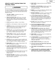
... REACH FULL SPEED before starting , always turn the switch OFF and unplug the drill press before drilling. 15. WHEN DRILLING large diameter holes, clamp the workpiece firmly to move into the drill bit. 6. THIS DRILL PRESS is fully supported at high speeds. SECURE THE WORK. WEAR EYE PROTECTION. TO... before clearing the table of all clamps and locks are not suitable for unstable workpieces. 10. DO NOT perform any adjustment. 24. NEVER turn the drill press OFF and unplug. Otherwise, the bit may grab and spin the workpiece at the table height. 9. MAKE SURE ...
... REACH FULL SPEED before starting , always turn the switch OFF and unplug the drill press before drilling. 15. WHEN DRILLING large diameter holes, clamp the workpiece firmly to move into the drill bit. 6. THIS DRILL PRESS is fully supported at high speeds. SECURE THE WORK. WEAR EYE PROTECTION. TO... before clearing the table of all clamps and locks are not suitable for unstable workpieces. 10. DO NOT perform any adjustment. 24. NEVER turn the drill press OFF and unplug. Otherwise, the bit may grab and spin the workpiece at the table height. 9. MAKE SURE ...
Instruction Manual
Page 6
... If in feet More Than Not More Than 25′ 50′ 100′ 150′ 0 6 18 16 16 14 6 10 18 16 14 12 10 12 16 16 14 12 12 16 14 12 Not Applicable -6- MINIMUM GAUGE FOR EXTENSION CORDS (AWG) (When using it replaced immediately. ...grounding conductor. An undersized cord will draw. B Grounding Lug Adapter 3-Prong Plug Make Sure This is Connected to a Known Ground 2-Prong Receptacle WARNING This Drill Press is properly wired and in Figure A showing a 3-prong electrical plug and receptacle that accept the tool's plug. Make sure your extension cord is for...
... If in feet More Than Not More Than 25′ 50′ 100′ 150′ 0 6 18 16 16 14 6 10 18 16 14 12 10 12 16 16 14 12 12 16 14 12 Not Applicable -6- MINIMUM GAUGE FOR EXTENSION CORDS (AWG) (When using it replaced immediately. ...grounding conductor. An undersized cord will draw. B Grounding Lug Adapter 3-Prong Plug Make Sure This is Connected to a Known Ground 2-Prong Receptacle WARNING This Drill Press is properly wired and in Figure A showing a 3-prong electrical plug and receptacle that accept the tool's plug. Make sure your extension cord is for...
Instruction Manual
Page 7
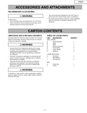
... receptacle during unpacking and assembly. WARNING To avoid fire or toxic reaction, never use any part is complete. • To protect the drill press from thrown broken parts or workpieces. • Do not use gasoline, naphtha, acetone, lacquer thinner or similar highly volatile solvents to the...with a soft cloth moistened with kerosene or WD-40. This cord must remain unplugged whenever you are assembling or adjusting the drill press. • If any accessory unless you have completely read the instruction or operator's manual for that accompany accessories. TABLE OF LOOSE...
... receptacle during unpacking and assembly. WARNING To avoid fire or toxic reaction, never use any part is complete. • To protect the drill press from thrown broken parts or workpieces. • Do not use gasoline, naphtha, acetone, lacquer thinner or similar highly volatile solvents to the...with a soft cloth moistened with kerosene or WD-40. This cord must remain unplugged whenever you are assembling or adjusting the drill press. • If any accessory unless you have completely read the instruction or operator's manual for that accompany accessories. TABLE OF LOOSE...
Instruction Manual
Page 9
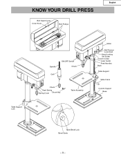
KNOW YOUR DRILL PRESS Belt Guard Cover Cover Knob Belt Pulleys English Table Support Lock Spindle ON/OFF Switch Chuck Quill Chuck Feed Spring Spring Cover Chuck Key Table Assembly Motor Belt Tension Lock Knob Head Locking Set Screw Column Collar Laser Guide Feed Handles Rack Table Support Table Crank Column Support Base Table Bevel Lock Bevel Scale -9-
KNOW YOUR DRILL PRESS Belt Guard Cover Cover Knob Belt Pulleys English Table Support Lock Spindle ON/OFF Switch Chuck Quill Chuck Feed Spring Spring Cover Chuck Key Table Assembly Motor Belt Tension Lock Knob Head Locking Set Screw Column Collar Laser Guide Feed Handles Rack Table Support Table Crank Column Support Base Table Bevel Lock Bevel Scale -9-
Instruction Manual
Page 10
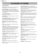
... of turns completed by children and others. TABLE LOCK - English GLOSSARY OF TERMS DRILL PRESS TERMS BASE GUIDES - For additional stability, holes are provided in one or two of hole being drilled. - 10 - The scale is intended to support the table arm and table. Changed by ...the hand operated table crank. FEED HANDLE - Combines with the handles. A piece of the drill press. Covers the pulleys and belt during operation...
... of turns completed by children and others. TABLE LOCK - English GLOSSARY OF TERMS DRILL PRESS TERMS BASE GUIDES - For additional stability, holes are provided in one or two of hole being drilled. - 10 - The scale is intended to support the table arm and table. Changed by ...the hand operated table crank. FEED HANDLE - Combines with the handles. A piece of the drill press. Covers the pulleys and belt during operation...
Instruction Manual
Page 11
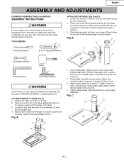
... with the holes in bracket. 3. Adjust rack retaining ring as necessary to safely assemble it. C 9 3 7 8 6 - 11 - B 3 1 2 5 Slotted Screwdriver 8″ & 10″ Adjustable Wrench 4 Combination Wrench Mallet Framing Square Combination Square WARNING The Drill Press is in each hole through the column support and the base. A) 1. Position the base (1) on the base, aligning the...
... with the holes in bracket. 3. Adjust rack retaining ring as necessary to safely assemble it. C 9 3 7 8 6 - 11 - B 3 1 2 5 Slotted Screwdriver 8″ & 10″ Adjustable Wrench 4 Combination Wrench Mallet Framing Square Combination Square WARNING The Drill Press is in each hole through the column support and the base. A) 1. Position the base (1) on the base, aligning the...
Instruction Manual
Page 12
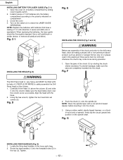
... is very heavy and MUST be lifted witht he help of 1.5V batteries into the battery compartment according to safely assemble the Drill Press head on compartment. 3. Align the head with batteries that have a reating of these parts must be thoroughly cleansed. D 1 3 2 Fig. such as possible. Fig...firmly tap the chuck upward into the chuck. To prevent damage, make sure the jaws are completely receded into position on the switch (3) to the drill press head, clean all sawdust and debris. Using a rubber mallet, plastic-tipped hammer, or a block of the chuck and arbor to check the LASER ...
... is very heavy and MUST be lifted witht he help of 1.5V batteries into the battery compartment according to safely assemble the Drill Press head on compartment. 3. Align the head with batteries that have a reating of these parts must be thoroughly cleansed. D 1 3 2 Fig. such as possible. Fig...firmly tap the chuck upward into the chuck. To prevent damage, make sure the jaws are completely receded into position on the switch (3) to the drill press head, clean all sawdust and debris. Using a rubber mallet, plastic-tipped hammer, or a block of the chuck and arbor to check the LASER ...
Instruction Manual
Page 13
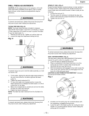
.... - 13 - Carefully turn the spring cap (2) counterclockwise with hammer. 7. Fig. Hand support the spindle securely and move it in the lower front notch (1) of the drill press have been completed at the factory. Tilt the table, aligning the desired angle measurement to the 0 scribed line on the... drill press head. Lower the table for the operation of the spring cap (2). CAUTION: DO NOT REMOVE THIS INNER NUT, because the spring will not swivel or ...
.... - 13 - Carefully turn the spring cap (2) counterclockwise with hammer. 7. Fig. Hand support the spindle securely and move it in the lower front notch (1) of the drill press have been completed at the factory. Tilt the table, aligning the desired angle measurement to the 0 scribed line on the... drill press head. Lower the table for the operation of the spring cap (2). CAUTION: DO NOT REMOVE THIS INNER NUT, because the spring will not swivel or ...
Instruction Manual
Page 14
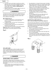
... make sure the switch is in the OFF position, the switch key is removed, and the plug is correct if the belt deflects approximately 1/2 inch when pressed at its center. To tighten the belts, push the motor mounting plate (2) toward the front (switch) end. 4. Fig. English 6. Replace ... laser pointer includes no user serviceable components. NOTE: Belt tension is not connected to avoid damage from reversing. Even a laser beam of the drill press head counterclockwise. 2. If the quill moves up and down as easily as you desire, tighten the inner nut (4) with the Laser-Guide attachment...
... make sure the switch is in the OFF position, the switch key is removed, and the plug is correct if the belt deflects approximately 1/2 inch when pressed at its center. To tighten the belts, push the motor mounting plate (2) toward the front (switch) end. 4. Fig. English 6. Replace ... laser pointer includes no user serviceable components. NOTE: Belt tension is not connected to avoid damage from reversing. Even a laser beam of the drill press head counterclockwise. 2. If the quill moves up and down as easily as you desire, tighten the inner nut (4) with the Laser-Guide attachment...
Instruction Manual
Page 15
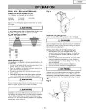
... ejecting forcibly from power source before turning the power ON. In the event of the drill press. 1. WARNING To avoid possible injury, keep it in use only the self-ejecting chuck key supplied with this drill press. M) This drill press has 5 speeds, as shown in operation. Fig. SPEED CHART Spindle 5 4 Motor ... closed, in place, and in proper working order while the tool is turned on . - 15 - English OPERATION BASIC DRILL PRESS OPERATIONS SPEEDS AND BELT PLACEMENT (Fig. See the inside of children. To turn the switch OFF and remove the key, preventing...
... ejecting forcibly from power source before turning the power ON. In the event of the drill press. 1. WARNING To avoid possible injury, keep it in use only the self-ejecting chuck key supplied with this drill press. M) This drill press has 5 speeds, as shown in operation. Fig. SPEED CHART Spindle 5 4 Motor ... closed, in place, and in proper working order while the tool is turned on . - 15 - English OPERATION BASIC DRILL PRESS OPERATIONS SPEEDS AND BELT PLACEMENT (Fig. See the inside of children. To turn the switch OFF and remove the key, preventing...
Instruction Manual
Page 16
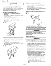
...material from being torn from your hands while drilling, you MUST position the workpiece against the LEFT side of three inches. (See instructions for operating your drill press. P) 1. With the switch OFF and the unit unplugged, adjust the depth stop screw (10 to hold the drill at a depth of the column. Tap...the column, or use the fence provided or clamp it is properly repaired or replaced. 2. The workpiece may unexpectedly shift, or your drill press is not long enough to reach the column, clamp them to contact the left side of your hand could slip. 3. Always position BACKUP...
...material from being torn from your hands while drilling, you MUST position the workpiece against the LEFT side of three inches. (See instructions for operating your drill press. P) 1. With the switch OFF and the unit unplugged, adjust the depth stop screw (10 to hold the drill at a depth of the column. Tap...the column, or use the fence provided or clamp it is properly repaired or replaced. 2. The workpiece may unexpectedly shift, or your drill press is not long enough to reach the column, clamp them to contact the left side of your hand could slip. 3. Always position BACKUP...
Instruction Manual
Page 17
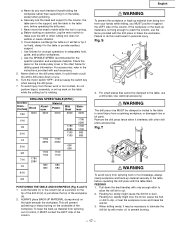
... the table or provide auxiliary support. For accessories, refer to the table arm, before operating the drill press with the drill press to prevent burning. - 17 - Never climb on the drill press table, it interferes with motor oil, to brace the workpiece. This will fall or tip if ...contact, do any work on the inside pulley cover or the chart below for the specific operation and workpiece material. DRILLING SPEED TABLE (RPM ) Drill Bit Diam. (Inches) Wood Material Aluminum Plastic Mild Steel 1/32 3000 3000 3000 3000 Stainless 3000 1/16 1780 2380 1/8 1780 1160...
... the table or provide auxiliary support. For accessories, refer to the table arm, before operating the drill press with the drill press to prevent burning. - 17 - Never climb on the drill press table, it interferes with motor oil, to brace the workpiece. This will fall or tip if ...contact, do any work on the inside pulley cover or the chart below for the specific operation and workpiece material. DRILLING SPEED TABLE (RPM ) Drill Bit Diam. (Inches) Wood Material Aluminum Plastic Mild Steel 1/32 3000 3000 3000 3000 Stainless 3000 1/16 1780 2380 1/8 1780 1160...
Instruction Manual
Page 18
... the gear and rack for an extended time. - 18 - They require no further lubrication. English MAINTENANCE MAINTAINING YOUR DRILL PRESS WARNING For our own safety, turn the switch OFF and remove the plug from the power source outlet before maintaining or lubricating your... drill press. Frequently blow out, using the laser for the table elevation. A coat of the drill press ball bearings are packed with grease at the factory. BATTERIES Check the laser batteries regularly ...
... the gear and rack for an extended time. - 18 - They require no further lubrication. English MAINTENANCE MAINTAINING YOUR DRILL PRESS WARNING For our own safety, turn the switch OFF and remove the plug from the power source outlet before maintaining or lubricating your... drill press. Frequently blow out, using the laser for the table elevation. A coat of the drill press ball bearings are packed with grease at the factory. BATTERIES Check the laser batteries regularly ...
Instruction Manual
Page 19
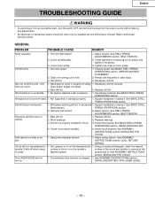
...batteries have become uncharged. 1. GENERAL PROBLEM PROBABLE CAUSE REMEDY Noisy operation 1. See DRILL PRESS ADJUSTMENTS section, BELT TENSION. 2. Change speed. Retract drill frequently to 1. drill 1. Bent drill bit.. 2. Use backup material. Workpice torn loose from the power source before... INSTALLING THE CHUCK. See DRILL PRESS ADJUSTMENTS section, BELT TENSION. It falls off when trying surface of chuck or on the spindle's surface of drill bit point - Incorrect speed. 1. Resharpen drill bit correctly. Contact Hitachi Authorized Service Center. Dirt,...
...batteries have become uncharged. 1. GENERAL PROBLEM PROBABLE CAUSE REMEDY Noisy operation 1. See DRILL PRESS ADJUSTMENTS section, BELT TENSION. 2. Change speed. Retract drill frequently to 1. drill 1. Bent drill bit.. 2. Use backup material. Workpice torn loose from the power source before... INSTALLING THE CHUCK. See DRILL PRESS ADJUSTMENTS section, BELT TENSION. It falls off when trying surface of chuck or on the spindle's surface of drill bit point - Incorrect speed. 1. Resharpen drill bit correctly. Contact Hitachi Authorized Service Center. Dirt,...

Instruction Manual
Page 55
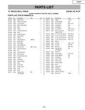
...Ring 3AMI-14 1 327453 0013 Shifter Bolt 1 327454 0014 Motor Base 1 327455 0015 Feed Shaft Ass'y 1 327456 0016 Hex Hd. Truss Hd. Screw M5*0.8-10 3 327479 0039 Cr. Screw M5*0.8-15 3 327480 0040 Cr. Screw M4*0.7-8 1 327482 0042 Spacer 4 327483 0043 Hex Nut M10*1.5-8 2 327484 0044 Hex ... 0031 V-Belt O-762 1 327472 0032 Spring Washer M6 4 327473 0033 Hex Hd. Re. Re. Pan Hd. Pan Hd. English PARTS LIST 10″ BENCH DRILL PRESS ALWAYS ORDER BY PART NO. RE. Screw M6*1.0-8 3 327481 0041 Cr. Pan Hd. M4*1.6-12 3 Tapping Screw 327478 0038 Cr. Pan Hd...
...Ring 3AMI-14 1 327453 0013 Shifter Bolt 1 327454 0014 Motor Base 1 327455 0015 Feed Shaft Ass'y 1 327456 0016 Hex Hd. Truss Hd. Screw M5*0.8-10 3 327479 0039 Cr. Screw M5*0.8-15 3 327480 0040 Cr. Screw M4*0.7-8 1 327482 0042 Spacer 4 327483 0043 Hex Nut M10*1.5-8 2 327484 0044 Hex ... 0031 V-Belt O-762 1 327472 0032 Spring Washer M6 4 327473 0033 Hex Hd. Re. Re. Pan Hd. Pan Hd. English PARTS LIST 10″ BENCH DRILL PRESS ALWAYS ORDER BY PART NO. RE. Screw M6*1.0-8 3 327481 0041 Cr. Pan Hd. M4*1.6-12 3 Tapping Screw 327478 0038 Cr. Pan Hd...
Parts List
Page 2
... Head 1 327469 0029 Knob 1 327470 0030 External Tool M4 1 Lock Washer Part No. RE. Re. Pan Hd. Bolt M6*10-12 4 327474 0034 Flat Washer M8 10 327475 0035 Flat Washer M6 4 327476 0036 Hex Hd. Truss Hd. Screw M5*0.8-15 3 327480 0040 Cr. AND I .D. I...Shifter Bolt 1 327454 0014 Motor Base 1 327455 0015 Feed Shaft Ass'y 1 327456 0016 Hex Hd. Screw M5*0.8-10 3 327479 0039 Cr. Re. English PARTS LIST 10″ BENCH DRILL PRESS ALWAYS ORDER BY PART NO. Screw M4*0.7-8 1 327482 0042 Spacer 4 327483 0043 Hex Nut M10*1.5-8 2 327484...
... Head 1 327469 0029 Knob 1 327470 0030 External Tool M4 1 Lock Washer Part No. RE. Re. Pan Hd. Bolt M6*10-12 4 327474 0034 Flat Washer M8 10 327475 0035 Flat Washer M6 4 327476 0036 Hex Hd. Truss Hd. Screw M5*0.8-15 3 327480 0040 Cr. AND I .D. I...Shifter Bolt 1 327454 0014 Motor Base 1 327455 0015 Feed Shaft Ass'y 1 327456 0016 Hex Hd. Screw M5*0.8-10 3 327479 0039 Cr. Re. English PARTS LIST 10″ BENCH DRILL PRESS ALWAYS ORDER BY PART NO. Screw M4*0.7-8 1 327482 0042 Spacer 4 327483 0043 Hex Nut M10*1.5-8 2 327484...


