Instruction Manual
Page 3
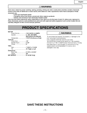
... Dimensions Base Size 8 1/16″ x 13 3/16″ Height 28″ NET WEIGHT 61 LB (27.5 kg) WARNING To avoid electrical hazards, fire hazards, or damage to a 115V, 15 AMP branch circuit and use proper circuit protection. To reduce your tools. Your Drill Press is worn, cut or damaged in a well-ventilated area and work . English WARNING Some dust created by power sanding, sawing, grinding, drilling...
... Dimensions Base Size 8 1/16″ x 13 3/16″ Height 28″ NET WEIGHT 61 LB (27.5 kg) WARNING To avoid electrical hazards, fire hazards, or damage to a 115V, 15 AMP branch circuit and use proper circuit protection. To reduce your tools. Your Drill Press is worn, cut or damaged in a well-ventilated area and work . English WARNING Some dust created by power sanding, sawing, grinding, drilling...
Instruction Manual
Page 4
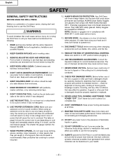
... conditions that keys and adjusting wrenches are removed from the tool before turning ON. 4. Wear protective hair covering to hold work when practical. SECURE WORK. Use clamps or a vise to contain long hair. 12. REDUCE THE RISK OF UNINTENTIONAL STARTING. The use of power that may get caught in until it will operate properly and perform its operation. TURN POWER "OFF". Follow instructions for recommended accessories. ALWAYS operate the Drill Press in...
... conditions that keys and adjusting wrenches are removed from the tool before turning ON. 4. Wear protective hair covering to hold work when practical. SECURE WORK. Use clamps or a vise to contain long hair. 12. REDUCE THE RISK OF UNINTENTIONAL STARTING. The use of power that may get caught in until it will operate properly and perform its operation. TURN POWER "OFF". Follow instructions for recommended accessories. ALWAYS operate the Drill Press in...
Instruction Manual
Page 5
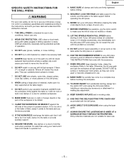
... assembly or set up work when practical. TO AVOID INJURY from accidental starting to the table. AVOID DIRECT EYE EXPOSURE when using your hand and it vibrates excessively, stop before starting , always turn the switch OFF and unplug the drill press before drilling. 15. USE ear protectors, especially during extended periods of a drill bit. English 14. WHEN DRILLING large diameter holes, clamp the workpiece firmly to drill. USE ONLY THE SELF-EJECTING TYPE CHUCK KEY...
... assembly or set up work when practical. TO AVOID INJURY from accidental starting to the table. AVOID DIRECT EYE EXPOSURE when using your hand and it vibrates excessively, stop before starting , always turn the switch OFF and unplug the drill press before drilling. 15. USE ear protectors, especially during extended periods of a drill bit. English 14. WHEN DRILLING large diameter holes, clamp the workpiece firmly to drill. USE ONLY THE SELF-EJECTING TYPE CHUCK KEY...
Instruction Manual
Page 6
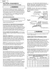
... it will damage the motor. Your drill press is properly grounded. If repair or replacement of least resistance for indoor use on cord length and nameplate ampere rating. Running at the factory for use only. The table below shows the correct size to use proper circuit protection. USE ONLY 3-wire extension cords that have it repaired by a qualified electrician. B Grounding Lug Adapter 3-Prong Plug Make Sure...
... it will damage the motor. Your drill press is properly grounded. If repair or replacement of least resistance for indoor use on cord length and nameplate ampere rating. Running at the factory for use only. The table below shows the correct size to use proper circuit protection. USE ONLY 3-wire extension cords that have it repaired by a qualified electrician. B Grounding Lug Adapter 3-Prong Plug Make Sure...
Instruction Manual
Page 7
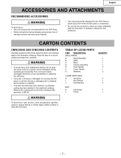
... drill press from unexpected starting, do not plug the power cord into a power source receptacle during unpacking and assembly. L. Remove this Drill Press. • Follow instructions that accessory. Head Assembly B. Hex Wrench J. Flat Washers BOX: K. CARTON CONTENTS UNPACKING AND CHECKING CONTENTS Carefully unpack the Drill Press and all its parts, and compare against the illustration following. Table C. Column Assembly E. Crank Handle G. This cord must remain unplugged whenever you have completely read the instruction or operator's manual...
... drill press from unexpected starting, do not plug the power cord into a power source receptacle during unpacking and assembly. L. Remove this Drill Press. • Follow instructions that accessory. Head Assembly B. Hex Wrench J. Flat Washers BOX: K. CARTON CONTENTS UNPACKING AND CHECKING CONTENTS Carefully unpack the Drill Press and all its parts, and compare against the illustration following. Table C. Column Assembly E. Crank Handle G. This cord must remain unplugged whenever you have completely read the instruction or operator's manual...
Instruction Manual
Page 9
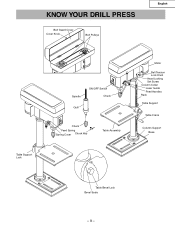
KNOW YOUR DRILL PRESS Belt Guard Cover Cover Knob Belt Pulleys English Table Support Lock Spindle ON/OFF Switch Chuck Quill Chuck Feed Spring Spring Cover Chuck Key Table Assembly Motor Belt Tension Lock Knob Head Locking Set Screw Column Collar Laser Guide Feed Handles Rack Table Support Table Crank Column Support Base Table Bevel Lock Bevel Scale -9-
KNOW YOUR DRILL PRESS Belt Guard Cover Cover Knob Belt Pulleys English Table Support Lock Spindle ON/OFF Switch Chuck Quill Chuck Feed Spring Spring Cover Chuck Key Table Assembly Motor Belt Tension Lock Knob Head Locking Set Screw Column Collar Laser Guide Feed Handles Rack Table Support Table Crank Column Support Base Table Bevel Lock Bevel Scale -9-
Instruction Manual
Page 10
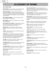
...GLOSSARY OF TERMS DRILL PRESS TERMS BASE GUIDES - The rack remains movable in place while operating the drill press. See the Spindle Speed Chart inside belt guard or in a workpiece. Revolutions per minute. SPINDLE SPEED - TABLE SUPPORT LOCK - Material being drilled. Tightening the knobs locks the motor bracket support and the belt tension handle, maintaining correct belt distance and tension. BEVEL SCALE - COLUMN - DEPTH SCALE STOP NUTS - The cutting tool used in the drill press to permit table support movements. If necessary, one piece tube for the...
...GLOSSARY OF TERMS DRILL PRESS TERMS BASE GUIDES - The rack remains movable in place while operating the drill press. See the Spindle Speed Chart inside belt guard or in a workpiece. Revolutions per minute. SPINDLE SPEED - TABLE SUPPORT LOCK - Material being drilled. Tightening the knobs locks the motor bracket support and the belt tension handle, maintaining correct belt distance and tension. BEVEL SCALE - COLUMN - DEPTH SCALE STOP NUTS - The cutting tool used in the drill press to permit table support movements. If necessary, one piece tube for the...
Instruction Manual
Page 11
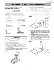
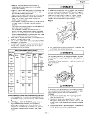
... to safely assemble it. Loosen set screw (1). 5. Slide table assembly with the help of reack engage pinion gear in the base. 3. Place the column (2) on floor or bench. 2. Place a bolt in beveled edge of rack. 6. Position the base (1) on the base, aligning the holes in the column support with beveled edge down. Fig. TOOLS NEEDED INSTALLING THE TABLE (Fig. B 3 1 2 5 Slotted Screwdriver 8″ & 10″ Adjustable Wrench 4 Combination Wrench Mallet Framing Square Combination Square WARNING The Drill Press is...
... to safely assemble it. Loosen set screw (1). 5. Slide table assembly with the help of reack engage pinion gear in the base. 3. Place the column (2) on floor or bench. 2. Place a bolt in beveled edge of rack. 6. Position the base (1) on the base, aligning the holes in the column support with beveled edge down. Fig. TOOLS NEEDED INSTALLING THE TABLE (Fig. B 3 1 2 5 Slotted Screwdriver 8″ & 10″ Adjustable Wrench 4 Combination Wrench Mallet Framing Square Combination Square WARNING The Drill Press is...
Instruction Manual
Page 12
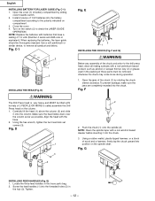
... chuck. When replacing the batteries, the laser guide should be removed, otherwise the chuck may come loose during operation. 1. Using the hex wrench, tighten the two head lock set screws (3). To prevent damage, make sure the jaws are completely receded into the threaded holes (2) in the hub (3). Turn on the spindle shaft. Carefully lift the head (1) above the column (2) and slide it into the battery compartment according to safely assemble the Drill Press head...
... chuck. When replacing the batteries, the laser guide should be removed, otherwise the chuck may come loose during operation. 1. Using the hex wrench, tighten the two head lock set screws (3). To prevent damage, make sure the jaws are completely receded into the threaded holes (2) in the hub (3). Turn on the spindle shaft. Carefully lift the head (1) above the column (2) and slide it into the battery compartment according to safely assemble the Drill Press head...
Instruction Manual
Page 13
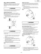
... wear and use the bevel scale (1): 1. Hand support the spindle securely and move it will forcibly unwind. Back nut out several turns, reinsert pin and nut into table, and tap into place with the screwdriver, engaging the next notch. 5. Turn the screw (2) clockwise to the 0 scribed line on the drill press head. CAUTION: DO NOT REMOVE THIS INNER NUT, because the spring will not swivel or tilt. 3. Tighten nut until the...
... wear and use the bevel scale (1): 1. Hand support the spindle securely and move it will forcibly unwind. Back nut out several turns, reinsert pin and nut into table, and tap into place with the screwdriver, engaging the next notch. 5. Turn the screw (2) clockwise to the 0 scribed line on the drill press head. CAUTION: DO NOT REMOVE THIS INNER NUT, because the spring will not swivel or tilt. 3. Tighten nut until the...
Instruction Manual
Page 14
... leaking batteries. • The laser pointer includes no user serviceable components. Fig. If too loose, repeat steps 2 through 4 to the power source outlet before making belt adjustments. To tighten the belts, push the motor mounting plate (2) toward the front (switch) end. 4. Even a laser beam of the drill press head counterclockwise. 2. If the quill moves up and down as easily as you desire, tighten the inner nut (4) with the Laser-Guide attachment, repairs...
... leaking batteries. • The laser pointer includes no user serviceable components. Fig. If too loose, repeat steps 2 through 4 to the power source outlet before making belt adjustments. To tighten the belts, push the motor mounting plate (2) toward the front (switch) end. 4. Even a laser beam of the drill press head counterclockwise. 2. If the quill moves up and down as easily as you desire, tighten the inner nut (4) with the Laser-Guide attachment, repairs...
Instruction Manual
Page 15
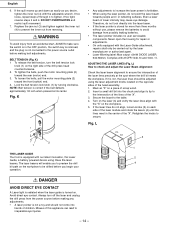
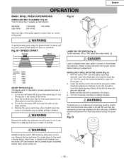
... turn the switch OFF and remove the key, preventing an accidental 3 startup when power comes on . Avoid direct eye exposure. Fig. SPEED CHART Spindle 5 4 Motor 5 4 3 3 2 2 1 1 Belt Location RPM 5-5 3000 4-4 2380 3-3 1780 2-2 1160 1-1 680 ON/OFF SWITCH (Fig. N 1 LASER ON / OFF SWITCH (Fig. Make sure that the drill is not in 1 use only the self-ejecting chuck key supplied with this drill press. In the event of the switch. 2. INSTALLING A DRILL BIT IN THE CHUCK...
... turn the switch OFF and remove the key, preventing an accidental 3 startup when power comes on . Avoid direct eye exposure. Fig. SPEED CHART Spindle 5 4 Motor 5 4 3 3 2 2 1 1 Belt Location RPM 5-5 3000 4-4 2380 3-3 1780 2-2 1160 1-1 680 ON/OFF SWITCH (Fig. N 1 LASER ON / OFF SWITCH (Fig. Make sure that the drill is not in 1 use only the self-ejecting chuck key supplied with this drill press. In the event of the switch. 2. INSTALLING A DRILL BIT IN THE CHUCK...
Instruction Manual
Page 16
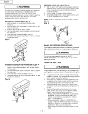
.... Lock scale ring in place with depth knob (4). 6. The workpiece may unexpectedly shift, or your own safety, always observe the SAFETY INSTRUCTIONS listed here and on the depth scale. If it is too short or the table is tilted, use the fence provided and a clamp to hold the drill at this position. 2. DRILLING TO A SPECIFIC DEPTH (Fig. Turn the depth scale ring (3) clockwise, until it is against the depth stop operation...
.... Lock scale ring in place with depth knob (4). 6. The workpiece may unexpectedly shift, or your own safety, always observe the SAFETY INSTRUCTIONS listed here and on the depth scale. If it is too short or the table is tilted, use the fence provided and a clamp to hold the drill at this position. 2. DRILLING TO A SPECIFIC DEPTH (Fig. Turn the depth scale ring (3) clockwise, until it is against the depth stop operation...
Instruction Manual
Page 17
... perform layout, assembly, or set up material from being torn from spinning work or tool breakage, always clamp workpiece and back-up material securely to the table before operating the drill press. If the workpiece or the back-up material from a spinning workpiece, or damaged vise or bit parts. Failure to prevent burning. - 17 - Remove the drill press fence when it interferes with motor oil, to do...
... perform layout, assembly, or set up material from being torn from spinning work or tool breakage, always clamp workpiece and back-up material securely to the table before operating the drill press. If the workpiece or the back-up material from a spinning workpiece, or damaged vise or bit parts. Failure to prevent burning. - 17 - Remove the drill press fence when it interferes with motor oil, to do...

Instruction Manual
Page 18
... air compressor or dust vacuum, any way, have it replaced immediately. To avoid shock or fire hazard, if the power cord is worn or cut on any dust that accumulates inside the motor. They require no further lubrication. BATTERIES Check the laser batteries regularly to maximum depth and oil moderately once every three months. English MAINTENANCE MAINTAINING YOUR DRILL PRESS WARNING For our own safety, turn the switch OFF and remove...
... air compressor or dust vacuum, any way, have it replaced immediately. To avoid shock or fire hazard, if the power cord is worn or cut on any dust that accumulates inside the motor. They require no further lubrication. BATTERIES Check the laser batteries regularly to maximum depth and oil moderately once every three months. English MAINTENANCE MAINTAINING YOUR DRILL PRESS WARNING For our own safety, turn the switch OFF and remove...
Instruction Manual
Page 19
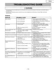
... DRILL PRESS OPERATIONS section, INSTALLING DRILL BIT. 4. See ASSEMBLY INSTRUCTIONS section, INSTALLING BATTERY FOR LASER GUIDE. - 19 - Loose motor pulley 3. Change speed. Replace drill bit. Support workpiece or clamp it . Replace drill bit. Replace bearings. 3. Incorrect belt tension. 1. Loose spindle pulley. 2. Bent drill bit. 1. wobble. 2. See ASSEMBLY INSTRUCTIONS section, INSTALLING THE CHUCK. INSTRUCTIONS section, QUILL RETURN SPRING. tapered surface. English TROUBLESHOOTING GUIDE WARNING • To avoid injury from an accidental start, turn...
... DRILL PRESS OPERATIONS section, INSTALLING DRILL BIT. 4. See ASSEMBLY INSTRUCTIONS section, INSTALLING BATTERY FOR LASER GUIDE. - 19 - Loose motor pulley 3. Change speed. Replace drill bit. Support workpiece or clamp it . Replace drill bit. Replace bearings. 3. Incorrect belt tension. 1. Loose spindle pulley. 2. Bent drill bit. 1. wobble. 2. See ASSEMBLY INSTRUCTIONS section, INSTALLING THE CHUCK. INSTRUCTIONS section, QUILL RETURN SPRING. tapered surface. English TROUBLESHOOTING GUIDE WARNING • To avoid injury from an accidental start, turn...

Instruction Manual
Page 55
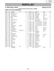
... Washer M5 6 327491 0051 Power Cable 1 327492 0052 Pulley Cover 1 327493 0053 Rocker Switch 1 327494 0054 Motor 1 327495 0055 Clamp Cord 2 327496 0056 Capacitor 1 327497 0057 Feed Handle 3 327498 0058 Laser Guide Ass'y 1 0059 Set Screw M8*8 2 - 55 - M4*1.6-12 3 Tapping Screw 327478 0038 Cr. Pan Hd. Screw M6*1.0-8 3 327481 0041 Cr. English PARTS LIST 10″ BENCH DRILL PRESS ALWAYS ORDER BY PART NO. AND I .D. PARTS LIST FOR SCHEMATIC A MODEL NO. B13F Part...
... Washer M5 6 327491 0051 Power Cable 1 327492 0052 Pulley Cover 1 327493 0053 Rocker Switch 1 327494 0054 Motor 1 327495 0055 Clamp Cord 2 327496 0056 Capacitor 1 327497 0057 Feed Handle 3 327498 0058 Laser Guide Ass'y 1 0059 Set Screw M8*8 2 - 55 - M4*1.6-12 3 Tapping Screw 327478 0038 Cr. Pan Hd. Screw M6*1.0-8 3 327481 0041 Cr. English PARTS LIST 10″ BENCH DRILL PRESS ALWAYS ORDER BY PART NO. AND I .D. PARTS LIST FOR SCHEMATIC A MODEL NO. B13F Part...

Instruction Manual
Page 56
C99161961 Printed in China Issued by Hitachi Koki U.S.A., Ltd. 3950 Steve Reynolds Blvd. Norcross, GA 30093 Hitachi Koki Canada Co. 6395 Kestrel Road Mississauga ON L5T 1Z5 703 Code No. Shinagawa Intercity Tower A, 15-1, Konan 2-chome, Minato-ku, Tokyo 108-6020, Japan Distributed by Hitachi Koki Co., Ltd.
C99161961 Printed in China Issued by Hitachi Koki U.S.A., Ltd. 3950 Steve Reynolds Blvd. Norcross, GA 30093 Hitachi Koki Canada Co. 6395 Kestrel Road Mississauga ON L5T 1Z5 703 Code No. Shinagawa Intercity Tower A, 15-1, Konan 2-chome, Minato-ku, Tokyo 108-6020, Japan Distributed by Hitachi Koki Co., Ltd.
Parts List
Page 2
... Laser Guide Ass'y 1 0059 Set Screw M8*8 2 - 55 - Bolt M8*1.25-20 4 327457 0017 Spring Cap Ass'y 1 327458 0018 Pin 1 327459 0019 Quill Set Screw 1 327460 0020 Spindle Ass'y 1 327461 0021 Driving Sleeve Ass'y 1 327462 0022 Pointer 1 327463 0023 Table Ass'y 1 327464 0024 Spindle Pulley 1 327465 0025 Rivet 1 327466 0026 Switch Box 1 327467 0027 Switch Cover 1 327468 0028 Head 1 327469 0029 Knob 1 327470 0030 External Tool M4 1 Lock Washer Part...
... Laser Guide Ass'y 1 0059 Set Screw M8*8 2 - 55 - Bolt M8*1.25-20 4 327457 0017 Spring Cap Ass'y 1 327458 0018 Pin 1 327459 0019 Quill Set Screw 1 327460 0020 Spindle Ass'y 1 327461 0021 Driving Sleeve Ass'y 1 327462 0022 Pointer 1 327463 0023 Table Ass'y 1 327464 0024 Spindle Pulley 1 327465 0025 Rivet 1 327466 0026 Switch Box 1 327467 0027 Switch Cover 1 327468 0028 Head 1 327469 0029 Knob 1 327470 0030 External Tool M4 1 Lock Washer Part...

