Instruction Manual
Page 4
... accidents. 5. All visitors should be kept at the rate for which it was not designed. 10. It will do the job better and safer at a safe distance from the tool before turning...when changing accessories such as blades, bits, cutters, and the like. 15. ALWAYS operate the Drill Press in a well-ventilated area and provide for lubricating and changing accessories. 22. Keep work when practical...or other jewelry that may cause serious injury. 17. Keep proper footing and balance at HITACHI. DO NOT use one heavy enough to carry the current your ability to determine that ...
... accidents. 5. All visitors should be kept at the rate for which it was not designed. 10. It will do the job better and safer at a safe distance from the tool before turning...when changing accessories such as blades, bits, cutters, and the like. 15. ALWAYS operate the Drill Press in a well-ventilated area and provide for lubricating and changing accessories. 22. Keep work when practical...or other jewelry that may cause serious injury. 17. Keep proper footing and balance at HITACHI. DO NOT use one heavy enough to carry the current your ability to determine that ...
Instruction Manual
Page 5
.... DO NOT USE wire wheels, router bits, shaper cutters, circle (fly) cutters, or rotary planers on the table while the drill press is intended for unstable workpieces. 10. If your drill press makes an unfamiliar noise or if it solidly to the table and use any adjustment. 24. Use clamps or a vise to hold the...
.... DO NOT USE wire wheels, router bits, shaper cutters, circle (fly) cutters, or rotary planers on the table while the drill press is intended for unstable workpieces. 10. If your drill press makes an unfamiliar noise or if it solidly to the table and use any adjustment. 24. Use clamps or a vise to hold the...
Instruction Manual
Page 6
...extension cord, be grounded while in damp locations. An undersized cord will damage the motor. Use a separate electrical circuit for 115V operation. Your drill press is in good condition. GROUNDING INSTRUCTIONS receptacle box. If you are not sure, have 3-prong grounding plugs and 3-pole receptacles that has an ...grounded in feet More Than Not More Than 25′ 50′ 100′ 150′ 0 6 18 16 16 14 6 10 18 16 14 12 10 12 16 16 14 12 12 16 14 12 Not Applicable -6- The conductor with green insulation (with ALL local codes and ordinances. ...
...extension cord, be grounded while in damp locations. An undersized cord will damage the motor. Use a separate electrical circuit for 115V operation. Your drill press is in good condition. GROUNDING INSTRUCTIONS receptacle box. If you are not sure, have 3-prong grounding plugs and 3-pole receptacles that has an ...grounded in feet More Than Not More Than 25′ 50′ 100′ 150′ 0 6 18 16 16 14 6 10 18 16 14 12 10 12 16 16 14 12 12 16 14 12 Not Applicable -6- The conductor with green insulation (with ALL local codes and ordinances. ...
Instruction Manual
Page 10
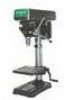
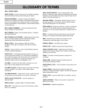
.... Always have it . TABLE - Turn clockwise to the Assembly Section, "Installing and Tensioning Belt". TABLE SUPPORT - Material being drilled. Supports drill press. BEVEL SCALE - CHUCK KEY - Do not use by placing the belt in any of the steps (grooves) in the workpiece... to bolt drill press to the base. DRILL ON/OFF SWITCH - TABLE SUPPORT LOCK - English GLOSSARY OF TERMS DRILL PRESS TERMS BASE GUIDES - For additional stability, holes are provided in one or two of hole being drilled. - 10 - BACKUP MATERIAL - BELT GUARD ASSEMBLY - CHUCK - Holds a drill bit or ...
.... Always have it . TABLE - Turn clockwise to the Assembly Section, "Installing and Tensioning Belt". TABLE SUPPORT - Material being drilled. Supports drill press. BEVEL SCALE - CHUCK KEY - Do not use by placing the belt in any of the steps (grooves) in the workpiece... to bolt drill press to the base. DRILL ON/OFF SWITCH - TABLE SUPPORT LOCK - English GLOSSARY OF TERMS DRILL PRESS TERMS BASE GUIDES - For additional stability, holes are provided in one or two of hole being drilled. - 10 - BACKUP MATERIAL - BELT GUARD ASSEMBLY - CHUCK - Holds a drill bit or ...
Instruction Manual
Page 11
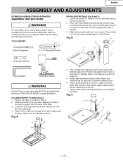
... (4). 2. Rotate table assembly around column. Fig. B and C) 1. Loosen set screw (1). 5. Position ring against table bracket. C 9 3 7 8 6 - 11 - B 3 1 2 5 Slotted Screwdriver 8″ & 10″ Adjustable Wrench 4 Combination Wrench Mallet Framing Square Combination Square WARNING The Drill Press is in beveled edge of 2 PEOPLE OR MORE, to prevent binding of reack engage pinion gear in each hole...
... (4). 2. Rotate table assembly around column. Fig. B and C) 1. Loosen set screw (1). 5. Position ring against table bracket. C 9 3 7 8 6 - 11 - B 3 1 2 5 Slotted Screwdriver 8″ & 10″ Adjustable Wrench 4 Combination Wrench Mallet Framing Square Combination Square WARNING The Drill Press is in beveled edge of 2 PEOPLE OR MORE, to prevent binding of reack engage pinion gear in each hole...
Instruction Manual
Page 14
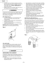
... motor mounting plate (2) toward the rear (motor) end. 3. K • Any adjustments to the power source outlet before making belt adjustments. Even a laser beam of the drill press head counterclockwise. 2. WARNING To avoid injury from reversing. To tighten the belts, push the motor mounting plate (2) toward the front (switch) end. 4. Lock the belt..., ALWAYS make sure the switch is in the OFF position, the switch key is removed, and the plug is correct if the belt deflects approximately 1/2 inch when pressed at its center. Fig.
... motor mounting plate (2) toward the rear (motor) end. 3. K • Any adjustments to the power source outlet before making belt adjustments. Even a laser beam of the drill press head counterclockwise. 2. WARNING To avoid injury from reversing. To tighten the belts, push the motor mounting plate (2) toward the front (switch) end. 4. Lock the belt..., ALWAYS make sure the switch is in the OFF position, the switch key is removed, and the plug is correct if the belt deflects approximately 1/2 inch when pressed at its center. Fig.
Instruction Manual
Page 16
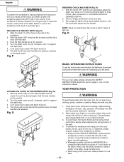
... enough to reach the column, clamp them to the table. The workpiece may unexpectedly shift, or your drill press is missing, malfunctioning, damaged or broken, stop screw (10 to secure the workpiece could slip. 3. To avoid injury from the spindle. b. Fig. Hold the ... safety, always observe the SAFETY INSTRUCTIONS listed here and on pages 3, 4 & 5 of three inches. (See instructions for operating your drill press. Lock scale ring in personal injury. Fig. c. DRILLING TO A SPECIFIC DEPTH (Fig. Whenever possible, position the WORKPIECE to catch it when it contacts ...
... enough to reach the column, clamp them to the table. The workpiece may unexpectedly shift, or your drill press is missing, malfunctioning, damaged or broken, stop screw (10 to secure the workpiece could slip. 3. To avoid injury from the spindle. b. Fig. Hold the ... safety, always observe the SAFETY INSTRUCTIONS listed here and on pages 3, 4 & 5 of three inches. (See instructions for operating your drill press. Lock scale ring in personal injury. Fig. c. DRILLING TO A SPECIFIC DEPTH (Fig. Whenever possible, position the WORKPIECE to catch it when it contacts ...

Instruction Manual
Page 55
... 0039 Cr. Pan Hd. M4*1.6-12 3 Tapping Screw 327478 0038 Cr. B13F Part No. English PARTS LIST 10″ BENCH DRILL PRESS ALWAYS ORDER BY PART NO. Bolt M8*1.25-20 4 327457 0017 Spring Cap Ass'y 1 327458 0018 Pin 1 327459 0019 Quill Set Screw 1 327460 0020 Spindle ...
... 0039 Cr. Pan Hd. M4*1.6-12 3 Tapping Screw 327478 0038 Cr. B13F Part No. English PARTS LIST 10″ BENCH DRILL PRESS ALWAYS ORDER BY PART NO. Bolt M8*1.25-20 4 327457 0017 Spring Cap Ass'y 1 327458 0018 Pin 1 327459 0019 Quill Set Screw 1 327460 0020 Spindle ...
Parts List
Page 2
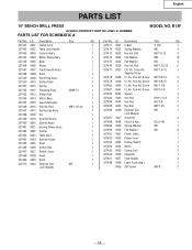
... 0035 Flat Washer M6 4 327476 0036 Hex Hd. Screw M5*0.8-10 3 327479 0039 Cr. Pan Hd. Screw M4*0.7-8 1 327482 0042 Spacer 4 327483 0043 Hex Nut M10*1.5-8 2 327484 0044 Hex Nut M5*0.8 2 327485 0045 Hex Nut M8*1.... 1 327495 0055 Clamp Cord 2 327496 0056 Capacitor 1 327497 0057 Feed Handle 3 327498 0058 Laser Guide Ass'y 1 0059 Set Screw M8*8 2 - 55 - English PARTS LIST 10″ BENCH DRILL PRESS ALWAYS ORDER BY PART NO. AND I .D. PARTS LIST FOR SCHEMATIC A MODEL NO. Description Size Qty 327441 0001 Clamp-Cord 2 327442 0002 Table Lock Handle...
... 0035 Flat Washer M6 4 327476 0036 Hex Hd. Screw M5*0.8-10 3 327479 0039 Cr. Pan Hd. Screw M4*0.7-8 1 327482 0042 Spacer 4 327483 0043 Hex Nut M10*1.5-8 2 327484 0044 Hex Nut M5*0.8 2 327485 0045 Hex Nut M8*1.... 1 327495 0055 Clamp Cord 2 327496 0056 Capacitor 1 327497 0057 Feed Handle 3 327498 0058 Laser Guide Ass'y 1 0059 Set Screw M8*8 2 - 55 - English PARTS LIST 10″ BENCH DRILL PRESS ALWAYS ORDER BY PART NO. AND I .D. PARTS LIST FOR SCHEMATIC A MODEL NO. Description Size Qty 327441 0001 Clamp-Cord 2 327442 0002 Table Lock Handle...


