Owners Guide
Page 2
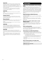
... or cracks. Never use harsh or abrasive cleaners! In the unlikely event of this User's Manual thoroughly, especially the Safety Instructions on -screen display system, displays the status of your plasma monitor, which could shorten its power consumption while it corresponds to a broad array of time, you encounter any difficulty in the set-up or operation of setting display controls. When connected to a VESA DPMS-compliant PC, the monitor cuts...
... or cracks. Never use harsh or abrasive cleaners! In the unlikely event of this User's Manual thoroughly, especially the Safety Instructions on -screen display system, displays the status of your plasma monitor, which could shorten its power consumption while it corresponds to a broad array of time, you encounter any difficulty in the set-up or operation of setting display controls. When connected to a VESA DPMS-compliant PC, the monitor cuts...
Owners Guide
Page 3
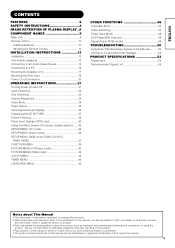
...Speaker Unit 17 Mounting the Side Input 19 Power Cord Connection 20 OPERATING INSTRUCTIONS 21 Turning Power On and Off 21 Input Switching 22 Size Switching 22 Volume Adjustment 24 Audio Mute 24 Power Swivel 25 Input Signal Screen Display 26 Displaying MULTI PICTURE 27 Picture Freezing 29 Photo Input Display (37/42 only 30 Using the Menu Screen (On-screen display system) ......33 SETUP MENU (TV mode 34 SETUP MENU (Video mode 36 SETUP MENU (RGB mode: RGB1 (DVI-PC), RGB2 (RGB 37 FUNCTION MENU 39 PICTURE MENU (TV/Video mode 40 PICTURE MENU (RGB mode 43 AUDIO MENU 44 TIMER MENU...
...Speaker Unit 17 Mounting the Side Input 19 Power Cord Connection 20 OPERATING INSTRUCTIONS 21 Turning Power On and Off 21 Input Switching 22 Size Switching 22 Volume Adjustment 24 Audio Mute 24 Power Swivel 25 Input Signal Screen Display 26 Displaying MULTI PICTURE 27 Picture Freezing 29 Photo Input Display (37/42 only 30 Using the Menu Screen (On-screen display system) ......33 SETUP MENU (TV mode 34 SETUP MENU (Video mode 36 SETUP MENU (RGB mode: RGB1 (DVI-PC), RGB2 (RGB 37 FUNCTION MENU 39 PICTURE MENU (TV/Video mode 40 PICTURE MENU (RGB mode 43 AUDIO MENU 44 TIMER MENU...
Owners Guide
Page 4
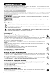
...; Never remove any shock or impact. Never attempt to make repairs yourself because this product, please read these symbols are present. Never disassemble or modify the monitor. WARNING Never use could result in personal injury or even death due to incorrect handling. In such case, immediately turn off the power switch, disconnect the power plug from the power outlet and...
...; Never remove any shock or impact. Never attempt to make repairs yourself because this product, please read these symbols are present. Never disassemble or modify the monitor. WARNING Never use could result in personal injury or even death due to incorrect handling. In such case, immediately turn off the power switch, disconnect the power plug from the power outlet and...
Owners Guide
Page 7
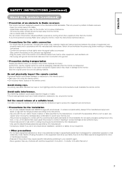
... find a problem receiving Radio when using the switch on the remote control. Disposal of the cabinet that for the cable connection - You can check if this . Do not use the attachments/accessories specified by the manufacturer, or sold with the fixings provided according to the international EMI standards. Switch off and withdraw the power plug before making or changing connections. - around the monitor. Follow instructions for infirm...
... find a problem receiving Radio when using the switch on the remote control. Disposal of the cabinet that for the cable connection - You can check if this . Do not use the attachments/accessories specified by the manufacturer, or sold with the fixings provided according to the international EMI standards. Switch off and withdraw the power plug before making or changing connections. - around the monitor. Follow instructions for infirm...
Owners Guide
Page 11
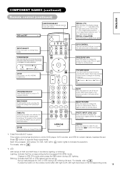
.... RECALL (Video/RGB) Press this button to normal picture. Each time pressed, picture mode is changed in following sequence. For details, refer to select a TV program directly. TIME (TV) Pressing this button can use these buttons to 48 If press the button on the remote control after LED light is off the set . SOUND MODE You may recall the picture mode by On-Screen display when receiving a TV program on the screen including TELETEXT service with a lamp. *1 DVD and SAT *2 INPUT SELECT...
.... RECALL (Video/RGB) Press this button to normal picture. Each time pressed, picture mode is changed in following sequence. For details, refer to select a TV program directly. TIME (TV) Pressing this button can use these buttons to 48 If press the button on the remote control after LED light is off the set . SOUND MODE You may recall the picture mode by On-Screen display when receiving a TV program on the screen including TELETEXT service with a lamp. *1 DVD and SAT *2 INPUT SELECT...
Owners Guide
Page 14
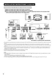
...the monitor is turned off . (3) Use a commercially available cable and connector to connect the signal input terminal on the main unit. Speaker (R) Monitor (rear panel) Speaker (L) To component input terminals To component output terminals To audio output terminals Power cord To composite output terminal To audio output terminals To composite input terminals To audio input terminals To composite output terminals To audio output terminals To S video output terminal To audio output terminals To component To component input terminals output terminals Antenna Set-Top Box DVD Player VTR...
...the monitor is turned off . (3) Use a commercially available cable and connector to connect the signal input terminal on the main unit. Speaker (R) Monitor (rear panel) Speaker (L) To component input terminals To component output terminals To audio output terminals Power cord To composite output terminal To audio output terminals To composite input terminals To audio input terminals To composite output terminals To audio output terminals To S video output terminal To audio output terminals To component To component input terminals output terminals Antenna Set-Top Box DVD Player VTR...
Owners Guide
Page 16
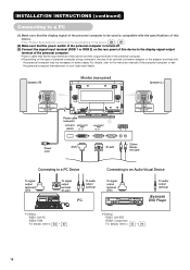
... 16 Speaker (R) Monitor (rear panel) Speaker (L) Power cable connector Power cord (DVI) (D-sub) 3.5mm Stereo mini jack Connecting to a PC Device To signal output terminal (DVI) To signal output terminal (D-sub) To audio output terminal PC Connecting to an Audio Visual Device To signal output terminal (DVI) To audio output terminal (Example) DVD Player • Setting RGB1: DVI-PC RGB2: RGB For details, refer to 56 ȁ 57 • Setting RGB1: DVI-STB RGB2: Component For details, refer to the instruction manual of...
... 16 Speaker (R) Monitor (rear panel) Speaker (L) Power cable connector Power cord (DVI) (D-sub) 3.5mm Stereo mini jack Connecting to a PC Device To signal output terminal (DVI) To signal output terminal (D-sub) To audio output terminal PC Connecting to an Audio Visual Device To signal output terminal (DVI) To audio output terminal (Example) DVD Player • Setting RGB1: DVI-PC RGB2: RGB For details, refer to 56 ȁ 57 • Setting RGB1: DVI-STB RGB2: Component For details, refer to the instruction manual of...
Owners Guide
Page 25
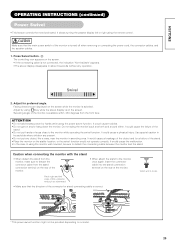
... using key while the swivel display is turned off when removing or connecting the power cord, the connector cables, and the speaker cables. 1. It would cause a breakage of the object and /or a failure of the stand. • Place the monitor on the screen. It would not operate correctly. The controlling icon appears on a model. 25 It could cause the failure of using the remote control. Adjust for stand connecting cable is not connected...
... using key while the swivel display is turned off when removing or connecting the power cord, the connector cables, and the speaker cables. 1. It would cause a breakage of the object and /or a failure of the stand. • Place the monitor on the screen. It would not operate correctly. The controlling icon appears on a model. 25 It could cause the failure of using the remote control. Adjust for stand connecting cable is not connected...
Owners Guide
Page 31
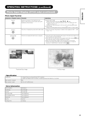
... of 16 images per one page by using ( , , , ) key. • Display the next or previous thumbnail-view of pictures. • Interval time during the thumbnail or the full view. ENGLISH OPERATING INSTRUCTIONS (continued) Photo Input Display (37/42 only) (continued) Photo Input Function Buttons on Remote Control Function PHOTO Display the pictures in the full size by ᕃ camera. 500 8176 x 8176 JPEG format • Error Information PHOTO INPUT Accessing...
... of 16 images per one page by using ( , , , ) key. • Display the next or previous thumbnail-view of pictures. • Interval time during the thumbnail or the full view. ENGLISH OPERATING INSTRUCTIONS (continued) Photo Input Display (37/42 only) (continued) Photo Input Function Buttons on Remote Control Function PHOTO Display the pictures in the full size by ᕃ camera. 500 8176 x 8176 JPEG format • Error Information PHOTO INPUT Accessing...
Owners Guide
Page 32
... a digital camera and a USB card reader to each image content when switching pages. • Contrast will decrease automatically if stationary images such as digital still photos are left on the screen for audio and moving images taken other than 3 minutes. • The OSD message "No Connection" is displayed in case of a digital camera or USB card reader, or displaying "Loading", do not turn the power off/standby mode nor remove/insert USB cable...
... a digital camera and a USB card reader to each image content when switching pages. • Contrast will decrease automatically if stationary images such as digital still photos are left on the screen for audio and moving images taken other than 3 minutes. • The OSD message "No Connection" is displayed in case of a digital camera or USB card reader, or displaying "Loading", do not turn the power off/standby mode nor remove/insert USB cable...
Owners Guide
Page 34
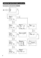
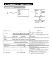
... ----- OPERATING INSTRUCTIONS (continued) SETUP MENU (TV mode) MENU Picture Audio Timer Function Setup Language Select OK Set Setup Auto Tuning Manual Tuning Fine Tuning Sort Teletext Language Auto Off Select OK Set Off Return 34 Setup Auto Tuning Manual Tuning Fine Tuning Sort Teletext Language Auto Off Select OK Set Off Return Setup Auto Tuning Manual Tuning Fine Tuning Sort Teletext Language Auto Off Select OK Set Off Return Setup Manual Tuning Position Frequency Name Sound System Color System...
... ----- OPERATING INSTRUCTIONS (continued) SETUP MENU (TV mode) MENU Picture Audio Timer Function Setup Language Select OK Set Setup Auto Tuning Manual Tuning Fine Tuning Sort Teletext Language Auto Off Select OK Set Off Return 34 Setup Auto Tuning Manual Tuning Fine Tuning Sort Teletext Language Auto Off Select OK Set Off Return Setup Auto Tuning Manual Tuning Fine Tuning Sort Teletext Language Auto Off Select OK Set Off Return Setup Manual Tuning Position Frequency Name Sound System Color System...
Owners Guide
Page 36
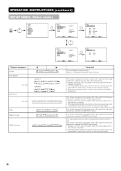
... is connected to AV1, 2 video input terminal. • Normally, set this to Auto. The signal mode of the input signal will be not available (grayed out). This step should correspond to the signal mode of the signal from the equipment that is connected to RGB2 D-sub terminal. OPERATING INSTRUCTIONS (continued) SETUP MENU (Video mode) MENU Picture Audio Timer Function Setup Language Select OK Set Setup System Color System Video Input RGB1 RGB2 System 1 DVI-STB Component HDTV Select OK Set Return Setup Color...
... is connected to AV1, 2 video input terminal. • Normally, set this to Auto. The signal mode of the input signal will be not available (grayed out). This step should correspond to the signal mode of the signal from the equipment that is connected to RGB2 D-sub terminal. OPERATING INSTRUCTIONS (continued) SETUP MENU (Video mode) MENU Picture Audio Timer Function Setup Language Select OK Set Setup System Color System Video Input RGB1 RGB2 System 1 DVI-STB Component HDTV Select OK Set Return Setup Color...
Owners Guide
Page 37
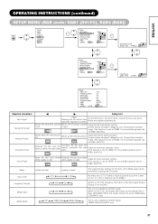
... display position. ENGLISH OPERATING INSTRUCTIONS (continued) SETUP MENU (RGB mode: RGB1 (DVI-PC), RGB2 (RGB)) MENU Picture Audio Timer Function Setup Language Select OK Set Setup Auto Adjust Horizontal Position Vertical Position Horizontal Clock Clock Phase Reset Select OK Set Adjust 0 + 31 - 20 10 Reset Return Horizontal Position Next / Prev Adjust 0 Return Setup Auto Adjust Horizontal Position Vertical Position Horizontal Clock Clock Phase Reset Select OK Set Adjust 0 + 31 - 20 10 Reset Return Clock Phase Next / Prev 10 Adjust Return Setup Input...
... display position. ENGLISH OPERATING INSTRUCTIONS (continued) SETUP MENU (RGB mode: RGB1 (DVI-PC), RGB2 (RGB)) MENU Picture Audio Timer Function Setup Language Select OK Set Setup Auto Adjust Horizontal Position Vertical Position Horizontal Clock Clock Phase Reset Select OK Set Adjust 0 + 31 - 20 10 Reset Return Horizontal Position Next / Prev Adjust 0 Return Setup Auto Adjust Horizontal Position Vertical Position Horizontal Clock Clock Phase Reset Select OK Set Adjust 0 + 31 - 20 10 Reset Return Clock Phase Next / Prev 10 Adjust Return Setup Input...
Owners Guide
Page 38
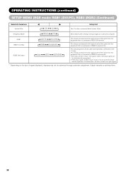
... connected to match the input signal. * Depending on the 1st step. OPERATING INSTRUCTIONS (continued) SETUP MENU (RGB mode: RGB1 (DVI-PC), RGB2 (RGB)) (Continued) Selected characters Vertical Filter Off On Setup hint Turn On when concerned about screen flicker. This should correspond to the signal mode of signal displayed, displays may not be optimized through automatic adjustment. The signal mode of the signal from the equipment that is connected to Auto. RGB1 DVI-PC DVI...
... connected to match the input signal. * Depending on the 1st step. OPERATING INSTRUCTIONS (continued) SETUP MENU (RGB mode: RGB1 (DVI-PC), RGB2 (RGB)) (Continued) Selected characters Vertical Filter Off On Setup hint Turn On when concerned about screen flicker. This should correspond to the signal mode of signal displayed, displays may not be optimized through automatic adjustment. The signal mode of the signal from the equipment that is connected to Auto. RGB1 DVI-PC DVI...
Owners Guide
Page 39
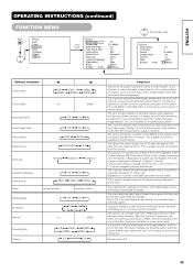
... the photo input function. Normally set intervals, to reduce the panel image retention that can be mitigated. ENGLISH OPERATING INSTRUCTIONS (continued) FUNCTION MENU MENU Picture Audio Timer Function Setup Language Select OK Set Function Screen Saver Screen Wipe Black Side Panel Video Power Save Freeze Mode Default Zoom Panel Life Luminance Manager Slide Interval Reset Select Set Off On 60Min. This is used to reduce the panel image retention. This selects the screen display size of the panel get lower...
... the photo input function. Normally set intervals, to reduce the panel image retention that can be mitigated. ENGLISH OPERATING INSTRUCTIONS (continued) FUNCTION MENU MENU Picture Audio Timer Function Setup Language Select OK Set Function Screen Saver Screen Wipe Black Side Panel Video Power Save Freeze Mode Default Zoom Panel Life Luminance Manager Slide Interval Reset Select Set Off On 60Min. This is used to reduce the panel image retention. This selects the screen display size of the panel get lower...
Owners Guide
Page 44
... when connected to preference. Favorite: This mode should be output from headphone on the selected picture. Dynamic Bass takes advantage of the ability of B (right picture) is from the speaker is located on A (left -side sound. This will be adjusted depending on the user's preference. Adjust it depending on user's preference. The original factory settings for Music. Suppresses bass. Speech: This selects the audio suitable...
... when connected to preference. Favorite: This mode should be output from headphone on the selected picture. Dynamic Bass takes advantage of the ability of B (right picture) is from the speaker is located on A (left -side sound. This will be adjusted depending on the user's preference. Adjust it depending on user's preference. The original factory settings for Music. Suppresses bass. Speech: This selects the audio suitable...
Owners Guide
Page 46
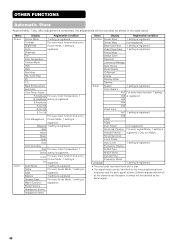
... Headphone Volume Headphone Select Menu Display Registration condition Function Screen Saver 1 setting is registered. Freeze Mode Default Zoom Panel Life Luminance Manager Slide Interval Mode Display ID Number Inverse Standby White Gamma Setup System 1 setting is registered. AV1 1 setting is Bass registered. Frequency Display WVGA Type WXGA Mode Vertical Filter Frequency Mode Language 1 setting is completed, the adjustments will be identified by the horizontal/vertical sync frequency and the sync signal polarity. Red Yellow Green Cyan Blue Color...
... Headphone Volume Headphone Select Menu Display Registration condition Function Screen Saver 1 setting is registered. Freeze Mode Default Zoom Panel Life Luminance Manager Slide Interval Mode Display ID Number Inverse Standby White Gamma Setup System 1 setting is registered. AV1 1 setting is Bass registered. Frequency Display WVGA Type WXGA Mode Vertical Filter Frequency Mode Language 1 setting is completed, the adjustments will be identified by the horizontal/vertical sync frequency and the sync signal polarity. Red Yellow Green Cyan Blue Color...
Owners Guide
Page 47
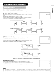
... between stereo and mono sound. STEREO sound broadcast When a stereo program is received, sound mode display will have no effect. Press the CH I / II button to select the sound to select the sound mode between monaural and forced 8 mono (sound is same). ̃ Each time the button is pressed, ̃ or M (force mono) appear cyclically on the screen. Sound multiplex signal received Red Green NICAM signal received NICAM Red Green Select or (force mono...
... between stereo and mono sound. STEREO sound broadcast When a stereo program is received, sound mode display will have no effect. Press the CH I / II button to select the sound to select the sound mode between monaural and forced 8 mono (sound is same). ̃ Each time the button is pressed, ̃ or M (force mono) appear cyclically on the screen. Sound multiplex signal received Red Green NICAM signal received NICAM Red Green Select or (force mono...

Owners Guide
Page 49
... where the sync signal cannot be operated using this remote control. Status Display When Mode Display is pressed. When the input signal does not match the monitor specifications or is displayed for the input terminal and the horizontal and vertical sync frequency. Invalid Scan Freq. 49 Recheck the input signal specifications. 54 ~ 57 RGB OFF -- -- A guide is in orange and the mode switches to ON, the input signal is switched or when the RECALL button is set up the...
... where the sync signal cannot be operated using this remote control. Status Display When Mode Display is pressed. When the input signal does not match the monitor specifications or is displayed for the input terminal and the horizontal and vertical sync frequency. Invalid Scan Freq. 49 Recheck the input signal specifications. 54 ~ 57 RGB OFF -- -- A guide is in orange and the mode switches to ON, the input signal is switched or when the RECALL button is set up the...
Owners Guide
Page 50
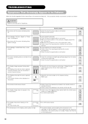
... the batteries in the remote control are OK. • Check to check • Check the way the power cable is lighting the phosphors by pressing button. • Turn off . • The message "No Sync. Please note that the switch of the display panel surface is high. • The plasma display panel is connected. • Press the power switch. See page 20 21 No sync signal is detected. • Check...
... the batteries in the remote control are OK. • Check to check • Check the way the power cable is lighting the phosphors by pressing button. • Turn off . • The message "No Sync. Please note that the switch of the display panel surface is high. • The plasma display panel is connected. • Press the power switch. See page 20 21 No sync signal is detected. • Check...


