User Manual
Page 10
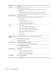
...● Windows 7 Professional (64- and 32-bit) ● Windows 7 Home Premium (64- and 32-bit) End-user replaceable parts: ● AC adapter 2 Chapter 1 Product description Category External media card Ports Keyboard/pointing devices Power requirements Operating system Serviceability ... (in black finish) TouchPad with multi-touch gestures Taps enabled as default Supports the following HP AC adapters: ● 65-W (non-smart) PFC RC V EM 3-wire HP AC adapter Supports the following batteries: ● 6-cell, 59 WHr 5.4 AH Li-ion battery Preinstalled: ● Windows 7 Home Basic (64-
...● Windows 7 Professional (64- and 32-bit) ● Windows 7 Home Premium (64- and 32-bit) End-user replaceable parts: ● AC adapter 2 Chapter 1 Product description Category External media card Ports Keyboard/pointing devices Power requirements Operating system Serviceability ... (in black finish) TouchPad with multi-touch gestures Taps enabled as default Supports the following HP AC adapters: ● 65-W (non-smart) PFC RC V EM 3-wire HP AC adapter Supports the following batteries: ● 6-cell, 59 WHr 5.4 AH Li-ion battery Preinstalled: ● Windows 7 Home Basic (64-
User Manual
Page 23
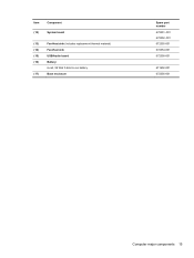
Item Component (12) System board (13) Fan-Heat sink (includes replacement thermal material) (14) Fan-Heat sink (15) USB/Audio board (16) Battery: 6-cell, 59 WHr 5.4AH Li-ion battery (17) Base enclosure Spare part number 672351-001 672352-001 672355-001 672354-001 672358-001 671602-001 672356-001 Computer major components 15
Item Component (12) System board (13) Fan-Heat sink (includes replacement thermal material) (14) Fan-Heat sink (15) USB/Audio board (16) Battery: 6-cell, 59 WHr 5.4AH Li-ion battery (17) Base enclosure Spare part number 672351-001 672352-001 672355-001 672354-001 672358-001 671602-001 672356-001 Computer major components 15
User Manual
Page 25
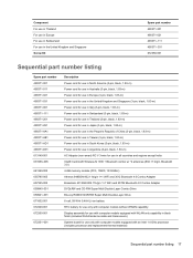
...-Layer Combo Drive Blu-ray ROM DVD±R/RW Super Multi Double-Layer Drive 6-cell, 59 WHr 5.4AH Li-ion battery RTC battery for use only with computer models without WWAN capability Display assembly for use with computer models equipped with WLAN only capability in... black finish (includes WLAN antenna cable and transceivers) System board for use only with computer models equipped with an Intel 1.4 GHz processor (includes processor and replacement...
...-Layer Combo Drive Blu-ray ROM DVD±R/RW Super Multi Double-Layer Drive 6-cell, 59 WHr 5.4AH Li-ion battery RTC battery for use only with computer models without WWAN capability Display assembly for use with computer models equipped with WLAN only capability in... black finish (includes WLAN antenna cable and transceivers) System board for use only with computer models equipped with an Intel 1.4 GHz processor (includes processor and replacement...
User Manual
Page 38
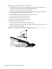
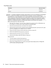
... steps: 1. Remove the 2 Phillips PM 2.0x3x0 screws securing the Power button board to the board. 30 Chapter 4 Removal and replacement procedures Remove the top cover (see Battery on page 28). 7. NOTE: The Power button board's cable is off or in Hibernation, turn the computer on, and then ...from the computer by first unplugging the power cord from the AC outlet and then unplugging the AC adapter from the computer. 4. Disconnect the battery cable (see Top cover on page 32). Disconnect all external devices connected to the computer. 3. Remove the Power button board and cable: ...
... steps: 1. Remove the 2 Phillips PM 2.0x3x0 screws securing the Power button board to the board. 30 Chapter 4 Removal and replacement procedures Remove the top cover (see Battery on page 28). 7. NOTE: The Power button board's cable is off or in Hibernation, turn the computer on, and then ...from the computer by first unplugging the power cord from the AC outlet and then unplugging the AC adapter from the computer. 4. Disconnect the battery cable (see Top cover on page 32). Disconnect all external devices connected to the computer. 3. Remove the Power button board and cable: ...
User Manual
Page 40
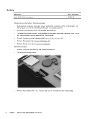
...the AC adapter from the computer. 4. Remove the keyboard (see Top cover on page 26). 6. Battery Description 6-cell, 59 WHr 5.4AH Li-ion battery Spare part number 671602-001 Before removing the battery, follow these steps: 1. Remove the top cover (see Keyboard on page 28). If you . 2.... Remove the 2 Phillips PM 2.0×3.0 screws that secure the battery to the computer. 3. Remove the battery: 1. Remove the base enclosure screws (see Base enclosure on , and then shut it down the computer. Disconnect all external devices ...
...the AC adapter from the computer. 4. Remove the keyboard (see Top cover on page 26). 6. Battery Description 6-cell, 59 WHr 5.4AH Li-ion battery Spare part number 671602-001 Before removing the battery, follow these steps: 1. Remove the top cover (see Keyboard on page 28). If you . 2.... Remove the 2 Phillips PM 2.0×3.0 screws that secure the battery to the computer. 3. Remove the battery: 1. Remove the base enclosure screws (see Base enclosure on , and then shut it down the computer. Disconnect all external devices ...
User Manual
Page 41
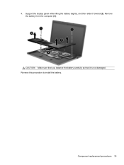
CAUTION: Make sure that you balance the battery carefully so that it forward (2). Support the display panel while lifting the battery slightly, and then slide it is not damaged. Component replacement procedures 33 Reverse this procedure to install the battery. 4. Remove the battery from the computer (3).
CAUTION: Make sure that you balance the battery carefully so that it forward (2). Support the display panel while lifting the battery slightly, and then slide it is not damaged. Component replacement procedures 33 Reverse this procedure to install the battery. 4. Remove the battery from the computer (3).
User Manual
Page 42
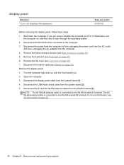
... the USB/Audio board cable from the computer. 4. The #2 WLAN antenna cable is connected to the WLAN module #1 terminal. Disconnect the battery cable (see Base enclosure on page 32). Disconnect the #1 and #2 WLAN antenna cables from the system board (1). 4. Disconnect all external... module (3). NOTE: The #1 WLAN antenna cable is connected to the computer. 3. Display panel Description 13.3-in Hibernation, turn the computer on page 36, 34 Chapter 4 Removal and replacement procedures Remove the keyboard (see Top cover on page 26). 6. Shut down through the operating system....
... the USB/Audio board cable from the computer. 4. The #2 WLAN antenna cable is connected to the WLAN module #1 terminal. Disconnect the battery cable (see Base enclosure on page 32). Disconnect the #1 and #2 WLAN antenna cables from the system board (1). 4. Disconnect all external... module (3). NOTE: The #1 WLAN antenna cable is connected to the computer. 3. Display panel Description 13.3-in Hibernation, turn the computer on page 36, 34 Chapter 4 Removal and replacement procedures Remove the keyboard (see Top cover on page 26). 6. Shut down through the operating system....
User Manual
Page 44
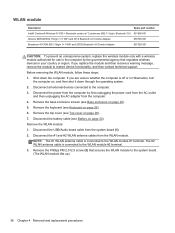
...655795-001 Broadcom 4313GN 802.11b/g/n 1×1 WiFi and 20702 Bluetooth 4.0 Combo Adapter 657325-001 CAUTION: To prevent an unresponsive system, replace the wireless module only with a wireless module authorized for use in the computer by first unplugging the power cord from the AC outlet ...and then unplugging the AC adapter from the computer. 4. Remove the base enclosure screws (see Battery on page 25). 5. Disconnect the battery cable (see Base enclosure on page 32). Remove the Phillips PM 2.0×2.5 screw (3) that regulates wireless devices in Hibernation...
...655795-001 Broadcom 4313GN 802.11b/g/n 1×1 WiFi and 20702 Bluetooth 4.0 Combo Adapter 657325-001 CAUTION: To prevent an unresponsive system, replace the wireless module only with a wireless module authorized for use in the computer by first unplugging the power cord from the AC outlet ...and then unplugging the AC adapter from the computer. 4. Remove the base enclosure screws (see Battery on page 25). 5. Disconnect the battery cable (see Base enclosure on page 32). Remove the Phillips PM 2.0×2.5 screw (3) that regulates wireless devices in Hibernation...
User Manual
Page 45
... (see Base enclosure on page 26). 6. Remove the base enclosure screws (see Battery on , and then shut it down the computer. Disconnect the Phillips PM 2.0x2.0 screw securing the USB/Audio board (2). Component replacement procedures 37 Remove the WLAN module by first unplugging the power cord from the AC outlet and then...
... (see Base enclosure on page 26). 6. Remove the base enclosure screws (see Battery on , and then shut it down the computer. Disconnect the Phillips PM 2.0x2.0 screw securing the USB/Audio board (2). Component replacement procedures 37 Remove the WLAN module by first unplugging the power cord from the AC outlet and then...
User Manual
Page 47
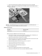
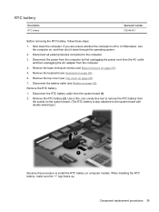
... or in Hibernation, turn the computer on computer models. Remove the base enclosure screws (see Battery on page 25). 5. Remove the RTC battery (2). Component replacement procedures 39 RTC battery Description RTC battery Spare part number 672349-001 Before removing the RTC battery, follow these steps: 1. Disconnect the power from the computer by first unplugging the power...
... or in Hibernation, turn the computer on computer models. Remove the base enclosure screws (see Battery on page 25). 5. Remove the RTC battery (2). Component replacement procedures 39 RTC battery Description RTC battery Spare part number 672349-001 Before removing the RTC battery, follow these steps: 1. Disconnect the power from the computer by first unplugging the power...
User Manual
Page 48
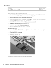
Disconnect the battery cable (see Keyboard on page 26). 6. Shut down through the operating system. 2. Disconnect all external devices connected to reassemble and install the hard drive. 40 Chapter 4 Removal and replacement procedures Disconnect the power from the computer by first unplugging the power cord... from the AC outlet and then unplugging the AC adapter from the computer. 4. Remove the keyboard (see Battery on page 25). 5. Remove the top ...
Disconnect the battery cable (see Keyboard on page 26). 6. Shut down through the operating system. 2. Disconnect all external devices connected to reassemble and install the hard drive. 40 Chapter 4 Removal and replacement procedures Disconnect the power from the computer by first unplugging the power cord... from the AC outlet and then unplugging the AC adapter from the computer. 4. Remove the keyboard (see Battery on page 25). 5. Remove the top ...
User Manual
Page 49
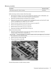
Remove the keyboard (see Top cover on page 26). 6. Remove the memory module (3). Component replacement procedures 41 Remove the top cover (see Keyboard on page 28). 7. Spread the retaining tabs (1) on each side of the memory module slot to ...install a memory module. Remove the memory module: 1. Disconnect the power from the computer by the edges only. Reverse this procedure to the computer. 3. Disconnect the battery cable (see Base enclosure on page 32). Slide the memory module forward (2). 3. Memory module Description 4-GB memory module (PC3, 10600, 1333-MHz) Spare part ...
Remove the keyboard (see Top cover on page 26). 6. Remove the memory module (3). Component replacement procedures 41 Remove the top cover (see Keyboard on page 28). 7. Spread the retaining tabs (1) on each side of the memory module slot to ...install a memory module. Remove the memory module: 1. Disconnect the power from the computer by the edges only. Reverse this procedure to the computer. 3. Disconnect the battery cable (see Base enclosure on page 32). Slide the memory module forward (2). 3. Memory module Description 4-GB memory module (PC3, 10600, 1333-MHz) Spare part ...
User Manual
Page 50
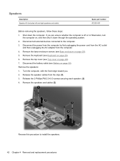
... unplugging the power cord from the AC outlet and then unplugging the AC adapter from the clips (1). 3. If you . 2. Disconnect the battery cable (see Base enclosure on page 26). 6. Release the speaker cables from the computer. 4. Reverse this procedure to the computer. 3. ...page 25). 5. Shut down through the operating system. 2. Disconnect all external devices connected to install the speakers. 42 Chapter 4 Removal and replacement procedures Remove the keyboard (see Top cover on , and then shut it down the computer. Release the 2 Phillips PM 2.0×3.0 screws securing...
... unplugging the power cord from the AC outlet and then unplugging the AC adapter from the clips (1). 3. If you . 2. Disconnect the battery cable (see Base enclosure on page 26). 6. Release the speaker cables from the computer. 4. Reverse this procedure to the computer. 3. ...page 25). 5. Shut down through the operating system. 2. Disconnect all external devices connected to install the speakers. 42 Chapter 4 Removal and replacement procedures Remove the keyboard (see Top cover on , and then shut it down the computer. Release the 2 Phillips PM 2.0×3.0 screws securing...
User Manual
Page 51
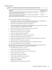
...see Display panel on page 25). 5. Remove the battery (see Hard drive on page 36). 9. Remove the...drive (see Battery on page 26), 6. If you are removed from the computer. 4. Component replacement procedures 43... and installed on the replacement system board: ● RTC battery (see RTC battery on page 39) &#...part kit includes replacement thermal material. Description For use only with computer models... not WWAN capability (includes replacement thermal material) Spare part number...connector and cable (see USB/Audio). When replacing the system board, be sure that the following...
...see Display panel on page 25). 5. Remove the battery (see Hard drive on page 36). 9. Remove the...drive (see Battery on page 26), 6. If you are removed from the computer. 4. Component replacement procedures 43... and installed on the replacement system board: ● RTC battery (see RTC battery on page 39) &#...part kit includes replacement thermal material. Description For use only with computer models... not WWAN capability (includes replacement thermal material) Spare part number...connector and cable (see USB/Audio). When replacing the system board, be sure that the following...
User Manual
Page 53
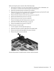
Remove the top cover (see Battery on page 32). 9. Disconnect the battery cable (see Top cover on page 42) Remove the power connector cable: 1. Before removing the power connector cable, follow these steps: 1. Disconnect the power ... then shut it down the computer. Disconnect all external devices connected to install the power connector cable and bracket. Remove the power connector cable (3). Component replacement procedures 45 Remove the display panel (see Base enclosure on page 34). 8. Disconnect the power connector cable (1) from the computer. 4. Remove the double-sided ...
Remove the top cover (see Battery on page 32). 9. Disconnect the battery cable (see Top cover on page 42) Remove the power connector cable: 1. Before removing the power connector cable, follow these steps: 1. Disconnect the power ... then shut it down the computer. Disconnect all external devices connected to install the power connector cable and bracket. Remove the power connector cable (3). Component replacement procedures 45 Remove the display panel (see Base enclosure on page 34). 8. Disconnect the power connector cable (1) from the computer. 4. Remove the double-sided ...
User Manual
Page 54
... to the computer. 3. Disconnect the power from the computer by high external temperatures, system power consumption, power management/battery conservation configurations, battery fast charging, and software requirements. Remove the 4 Phillips PM 2.0×3.0 screws securing the heat sink (2), and the... 2 Phillips PM 2.0×3.0 screws securing the fan (3). 46 Chapter 4 Removal and replacement procedures The computer uses an electric fan for ventilation. Remove the top cover (see Battery on page 26). 6. Disconnect the fan cable (1) from the computer. 4. Exhaust air...
... to the computer. 3. Disconnect the power from the computer by high external temperatures, system power consumption, power management/battery conservation configurations, battery fast charging, and software requirements. Remove the 4 Phillips PM 2.0×3.0 screws securing the heat sink (2), and the... 2 Phillips PM 2.0×3.0 screws securing the fan (3). 46 Chapter 4 Removal and replacement procedures The computer uses an electric fan for ventilation. Remove the top cover (see Battery on page 26). 6. Disconnect the fan cable (1) from the computer. 4. Exhaust air...
User Manual
Page 60
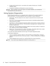
... computer. ● Run-in every sector of the screen, press esc. NOTE: After a message on -screen instructions. If the battery fails the test, contact HP support to stop a diagnostics test while it is functioning properly. Double-click the file that are available in System Diagnostics: ●... delete the downloaded file from your hard drive. 4. If the test detects a damaged sector, it reports an error, replace the memory modules immediately. ● Battery test-This test analyzes the condition of the memory modules. Click the diagnostic test you need to report the issue and ...
... computer. ● Run-in every sector of the screen, press esc. NOTE: After a message on -screen instructions. If the battery fails the test, contact HP support to stop a diagnostics test while it is functioning properly. Double-click the file that are available in System Diagnostics: ●... delete the downloaded file from your hard drive. 4. If the test detects a damaged sector, it reports an error, replace the memory modules immediately. ● Battery test-This test analyzes the condition of the memory modules. Click the diagnostic test you need to report the issue and ...
User Manual
Page 73
keyboard product description 2 removal 26 spare part numbers 13, 18, 26 keys Action 6 esc 6 fn 6 Windows applications 6 Windows logo 6 L left-side components 9 light components 7 lights battery 9 caps lock 7 hard drive 9 mute 7 power 7 TouchPad 8 wireless 7 M mass storage device precautions 20 removal 40 spare part numbers...recovering from the recovery discs 58 recovery discs 55 recovery, system 56 removal/replacement preliminaries 19 procedures 23 restore points 60 right-side components 10 RJ-45 (network) jack, identifying 9 RTC battery removal 39 spare part numbers 14, 17, 39 Rubber Feet Kit, ...
keyboard product description 2 removal 26 spare part numbers 13, 18, 26 keys Action 6 esc 6 fn 6 Windows applications 6 Windows logo 6 L left-side components 9 light components 7 lights battery 9 caps lock 7 hard drive 9 mute 7 power 7 TouchPad 8 wireless 7 M mass storage device precautions 20 removal 40 spare part numbers...recovering from the recovery discs 58 recovery discs 55 recovery, system 56 removal/replacement preliminaries 19 procedures 23 restore points 60 right-side components 10 RJ-45 (network) jack, identifying 9 RTC battery removal 39 spare part numbers 14, 17, 39 Rubber Feet Kit, ...
User Guide
Page 43
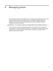
...conservation. To monitor the status of your computer battery, which is installed at the factory. Your computer has an internal rechargeable battery that can be replaced, contact customer support. 33 6 Managing power Your computer can operate on battery power and an AC power source is not ...available to charge the battery, it is important to monitor and conserve the battery charge. IMPORTANT: Do not attempt to replace your battery, or if the battery is only running on either battery power or external AC power...
...conservation. To monitor the status of your computer battery, which is installed at the factory. Your computer has an internal rechargeable battery that can be replaced, contact customer support. 33 6 Managing power Your computer can operate on battery power and an AC power source is not ...available to charge the battery, it is important to monitor and conserve the battery charge. IMPORTANT: Do not attempt to replace your battery, or if the battery is only running on either battery power or external AC power...
User Guide
Page 48
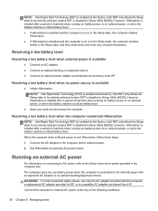
...AC adapter. ● Connect an optional docking or expansion device. ● Connect an optional power adapter purchased as an accessory from HP. Resolving a low battery level when the computer cannot exit Hibernation NOTE: Intel Rapid Start Technology (RST) is enabled at the factory. Exit Hibernation by...unless RST is disabled in Setup Utility (BIOS)). Intel RST only allows the Sleep state to AC external power with the computer, a replacement AC adapter provided by pressing the power button. WARNING! Connect the AC adapter to the computer and to be actively selected (unless RST...
...AC adapter. ● Connect an optional docking or expansion device. ● Connect an optional power adapter purchased as an accessory from HP. Resolving a low battery level when the computer cannot exit Hibernation NOTE: Intel Rapid Start Technology (RST) is enabled at the factory. Exit Hibernation by...unless RST is disabled in Setup Utility (BIOS)). Intel RST only allows the Sleep state to AC external power with the computer, a replacement AC adapter provided by pressing the power button. WARNING! Connect the AC adapter to the computer and to be actively selected (unless RST...


