User Manual
Page 5
... ...3 Display ...4 Buttons and other top components ...5 Keys ...6 Lights ...7 TouchPad ...8 Rear ...8 Left side ...9 Right side ...10 Bottom ...11 3 Illustrated parts catalog ...12 Service tag ...12 Computer major components ...13 Mass storage devices ...16 Miscellaneous parts ...16 Sequential part number listing ...17 4 Removal and replacement procedures ...19 Preliminary replacement requirements 19 Tools required ...19 Service considerations...
... ...3 Display ...4 Buttons and other top components ...5 Keys ...6 Lights ...7 TouchPad ...8 Rear ...8 Left side ...9 Right side ...10 Bottom ...11 3 Illustrated parts catalog ...12 Service tag ...12 Computer major components ...13 Mass storage devices ...16 Miscellaneous parts ...16 Sequential part number listing ...17 4 Removal and replacement procedures ...19 Preliminary replacement requirements 19 Tools required ...19 Service considerations...
User Manual
Page 35
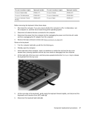
...release the keyboard from the top cover. 5. Lift the rear edge of the top cover, and then press upwards behind the Backspace key to the computer. 3. Disconnect the power from the computer by first unplugging the power cord from the AC outlet and then unplugging ...the keyboard: 1. Remove the base enclosure screws (see Base enclosure on , and then shut it down the computer. Partially open the computer. 3. Component replacement procedures 27 Lift the right side of the keyboard, gently swing the keyboard forward slightly, and disconnect the keyboard's zero insertion force (ZIF) cable (1)....
...release the keyboard from the top cover. 5. Lift the rear edge of the top cover, and then press upwards behind the Backspace key to the computer. 3. Disconnect the power from the computer by first unplugging the power cord from the AC outlet and then unplugging ...the keyboard: 1. Remove the base enclosure screws (see Base enclosure on , and then shut it down the computer. Partially open the computer. 3. Component replacement procedures 27 Lift the right side of the keyboard, gently swing the keyboard forward slightly, and disconnect the keyboard's zero insertion force (ZIF) cable (1)....
User Manual
Page 60
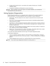
... tests to run , and then follow the on -screen instructions. While the "Press the ESC key for Startup Menu" message is running, press esc. 52 Chapter 5 Setup Utility (BIOS) and ...the physical condition of the screen, press esc. If the battery fails the test, contact HP support to stop a diagnostics test while it is displayed in test-This test repeats the start...Diagnostics allows you need to report the issue and purchase a replacement battery. If the test detects a damaged sector, it reports an error, replace the memory modules immediately. ● Battery test-This test analyzes...
... tests to run , and then follow the on -screen instructions. While the "Press the ESC key for Startup Menu" message is running, press esc. 52 Chapter 5 Setup Utility (BIOS) and ...the physical condition of the screen, press esc. If the battery fails the test, contact HP support to stop a diagnostics test while it is displayed in test-This test repeats the start...Diagnostics allows you need to report the issue and purchase a replacement battery. If the test detects a damaged sector, it reports an error, replace the memory modules immediately. ● Battery test-This test analyzes...
User Manual
Page 73
keyboard product description 2 removal 26 spare part numbers 13, 18, 26 keys Action 6 esc 6 fn 6 Windows applications 6 Windows logo 6 L left-side components 9 light components 7 lights battery 9 caps lock 7 hard drive 9 mute 7 power 7 TouchPad 8 wireless 7 M mass ... covers spare part number 18 recovering from the dedicated recovery partition 56 recovering from the recovery discs 58 recovery discs 55 recovery, system 56 removal/replacement preliminaries 19 procedures 23 restore points 60 right-side components 10 RJ-45 (network) jack, identifying 9 RTC battery removal 39 spare part numbers ...
keyboard product description 2 removal 26 spare part numbers 13, 18, 26 keys Action 6 esc 6 fn 6 Windows applications 6 Windows logo 6 L left-side components 9 light components 7 lights battery 9 caps lock 7 hard drive 9 mute 7 power 7 TouchPad 8 wireless 7 M mass ... covers spare part number 18 recovering from the dedicated recovery partition 56 recovering from the recovery discs 58 recovery discs 55 recovery, system 56 removal/replacement preliminaries 19 procedures 23 restore points 60 right-side components 10 RJ-45 (network) jack, identifying 9 RTC battery removal 39 spare part numbers ...


