User Manual
Page 10
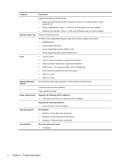
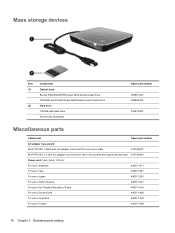
...Combo Adapter Push-pull insertion/removal HP Multi-Format Digital Media Reader supports the following digital card formats: ● MultiMediaCard ● Secure Digital (SD) Card ● Secure Digital High-Capacity (SDHC) Card ● Secure Digital Extended Capacity (SDxC) Card ● 3-pin AC power ●...spill-resistance (in black finish) TouchPad with multi-touch gestures Taps enabled as default Supports the following HP AC adapters: ● 65-W (non-smart) PFC RC V EM 3-wire HP AC adapter Supports the following batteries: ● 6-cell, 59 WHr 5.4 AH Li-ion battery Preinstalled: &#...
...Combo Adapter Push-pull insertion/removal HP Multi-Format Digital Media Reader supports the following digital card formats: ● MultiMediaCard ● Secure Digital (SD) Card ● Secure Digital High-Capacity (SDHC) Card ● Secure Digital Extended Capacity (SDxC) Card ● 3-pin AC power ●...spill-resistance (in black finish) TouchPad with multi-touch gestures Taps enabled as default Supports the following HP AC adapters: ● 65-W (non-smart) PFC RC V EM 3-wire HP AC adapter Supports the following batteries: ● 6-cell, 59 WHr 5.4 AH Li-ion battery Preinstalled: &#...
User Manual
Page 17
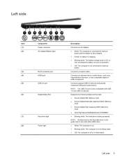
...-45 (network) jack (4) HDMI port (5) USB 3.0 port (6) Digital Media Slot (7) Hard drive light (8) Power light Description Connects an AC adapter. ● White: The computer is connected to external power and the battery is fully charged. ● Amber: A battery is charging. ● Blinking white: The battery... (UHS/MMC) ● Blinking white: The hard drive is off or in this guide refer to external power. Connects optional USB 3.0 devices and provide enhanced USB power performance. NOTE: All references to the hard disk drive in Hibernation. Connects a network cable.
...-45 (network) jack (4) HDMI port (5) USB 3.0 port (6) Digital Media Slot (7) Hard drive light (8) Power light Description Connects an AC adapter. ● White: The computer is connected to external power and the battery is fully charged. ● Amber: A battery is charging. ● Blinking white: The battery... (UHS/MMC) ● Blinking white: The hard drive is off or in this guide refer to external power. Connects optional USB 3.0 devices and provide enhanced USB power performance. NOTE: All references to the hard disk drive in Hibernation. Connects a network cable.
User Manual
Page 22
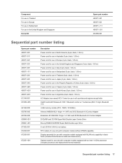
...cable): 672357-001 TouchPad button board (includes cable) NOTE: The top cover spare part kit includes the power button board and cable and the TouchPad and cable. 672357-001 Power connector cable (includes bracket) 672361-001 Memory modules (2, PC3, 10600, 1333-MHz): 4 GB 641369... 1030 + Bluetooth combo w/ *2 antennas (802.11 b/g/n, Bluetooth 3.0) 631956-005 Atheros 9485GN 802.11b/g/n 1×1 WiFi and 3012 Bluetooth 4.0 Combo Adapter 655795-005 Broadcom 4313GN 802.11b/g/n 1×1 WiFi and 20702 Bluetooth 4.0 Combo AdapterSPSWLAN 802.11bgn+BT4 BC HMC 1x1 VAL 657325-005 RTC battery:...
...cable): 672357-001 TouchPad button board (includes cable) NOTE: The top cover spare part kit includes the power button board and cable and the TouchPad and cable. 672357-001 Power connector cable (includes bracket) 672361-001 Memory modules (2, PC3, 10600, 1333-MHz): 4 GB 641369... 1030 + Bluetooth combo w/ *2 antennas (802.11 b/g/n, Bluetooth 3.0) 631956-005 Atheros 9485GN 802.11b/g/n 1×1 WiFi and 3012 Bluetooth 4.0 Combo Adapter 655795-005 Broadcom 4313GN 802.11b/g/n 1×1 WiFi and 20702 Bluetooth 4.0 Combo AdapterSPSWLAN 802.11bgn+BT4 BC HMC 1x1 VAL 657325-005 RTC battery:...
User Manual
Page 24
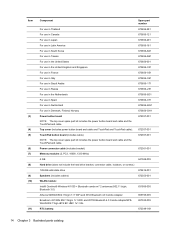
...-smart) for use only in India 613149-001 65-W PFC RC V 3-wire AC adapter (non-smart) for use in all countries and regions except India 613149-001 Power cord (3-pin, black, 1.83-m): For use in Australia 490371-011 For use in Italy 490371-061 For use in Japan 490371-291 For use...
...-smart) for use only in India 613149-001 65-W PFC RC V 3-wire AC adapter (non-smart) for use in all countries and regions except India 613149-001 Power cord (3-pin, black, 1.83-m): For use in Australia 490371-011 For use in Italy 490371-061 For use in Japan 490371-291 For use...
User Manual
Page 25
...use in the People's Republic of China (3-pin, black, 1.83-m) Power cord for use in Taiwan (3-pin, black, 1.83-m) Power cord for use in South Korea (3-pin, black, 1.83-m) Power cord for use in Argentina (3-pin, black, 1.83-m) AC Adapter (non-smart) RC V 3-wire for use in all countries and ...Bluetooth 3.0) 4-GB memory module (PC3, 10600, 1333-MHz) Atheros 9485GN 802.11b/g/n 1×1 WiFi and 3012 Bluetooth 4.0 Combo Adapter Broadcom 4313GN 802.11b/g/n 1×1 WiFi and 20702 Bluetooth 4.0 Combo Adapter DVD±RW and CD-RW Super Multi Double-Layer Combo Drive Blu-ray ROM DVD±R/RW Super Multi...
...use in the People's Republic of China (3-pin, black, 1.83-m) Power cord for use in Taiwan (3-pin, black, 1.83-m) Power cord for use in South Korea (3-pin, black, 1.83-m) Power cord for use in Argentina (3-pin, black, 1.83-m) AC Adapter (non-smart) RC V 3-wire for use in all countries and ...Bluetooth 3.0) 4-GB memory module (PC3, 10600, 1333-MHz) Atheros 9485GN 802.11b/g/n 1×1 WiFi and 3012 Bluetooth 4.0 Combo Adapter Broadcom 4313GN 802.11b/g/n 1×1 WiFi and 20702 Bluetooth 4.0 Combo Adapter DVD±RW and CD-RW Super Multi Double-Layer Combo Drive Blu-ray ROM DVD±R/RW Super Multi...
User Manual
Page 33
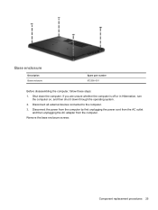
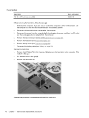
If you are unsure whether the computer is off or in Hibernation, turn the computer on, and then shut it down the computer. Remove the base enclosure screws: Component replacement procedures 25 Disconnect the power from the computer by first unplugging the power cord from the AC outlet and then unplugging the AC adapter from the computer. Disconnect all external devices connected to the computer. 3. Base enclosure Description Base enclosure Spare part number 672356-001 Before disassembling the computer, follow these steps: 1. Shut down through the operating system. 2.
If you are unsure whether the computer is off or in Hibernation, turn the computer on, and then shut it down the computer. Remove the base enclosure screws: Component replacement procedures 25 Disconnect the power from the computer by first unplugging the power cord from the AC outlet and then unplugging the AC adapter from the computer. Disconnect all external devices connected to the computer. 3. Base enclosure Description Base enclosure Spare part number 672356-001 Before disassembling the computer, follow these steps: 1. Shut down through the operating system. 2.
User Manual
Page 35
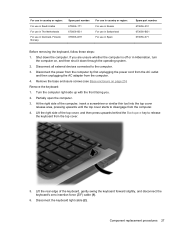
... Russia For use in Switzerland For use in Hibernation, turn the computer on page 25). Disconnect the power from the computer by first unplugging the power cord from the AC outlet and then unplugging the AC adapter from the top cover. 5. Lift the rear edge of the computer, insert a screwdriver or similar thin...
... Russia For use in Switzerland For use in Hibernation, turn the computer on page 25). Disconnect the power from the computer by first unplugging the power cord from the AC outlet and then unplugging the AC adapter from the top cover. 5. Lift the rear edge of the computer, insert a screwdriver or similar thin...
User Manual
Page 36
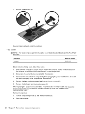
... board and cable and the TouchPad and cable. Remove the top cover: 1. Disconnect the power from the computer by first unplugging the power cord from the AC outlet and then unplugging the AC adapter from the defective top cover and installed on page 26). When replacing the top cover, be sure that the...
... board and cable and the TouchPad and cable. Remove the top cover: 1. Disconnect the power from the computer by first unplugging the power cord from the AC outlet and then unplugging the AC adapter from the defective top cover and installed on page 26). When replacing the top cover, be sure that the...
User Manual
Page 38
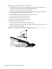
If you . 2. Disconnect the power from the computer by first unplugging the power cord from the AC outlet and then unplugging the AC adapter from the computer. 4. Remove the base enclosure screws (see Battery on page 28). 7. Remove the Power button board and cable: 1. Disconnect the battery cable... (see Base enclosure on , and then shut it down through the operating system. 2. Remove the Power button board ...
If you . 2. Disconnect the power from the computer by first unplugging the power cord from the AC outlet and then unplugging the AC adapter from the computer. 4. Remove the base enclosure screws (see Battery on page 28). 7. Remove the Power button board and cable: 1. Disconnect the battery cable... (see Base enclosure on , and then shut it down through the operating system. 2. Remove the Power button board ...
User Manual
Page 39
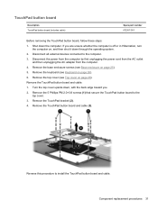
... are unsure whether the computer is off or in Hibernation, turn the computer on page 25). 5. Disconnect the power from the computer by first unplugging the power cord from the AC outlet and then unplugging the AC adapter from the computer. 4. Disconnect all external devices connected to the computer. 3. Remove the TouchPad bracket (2). 4.
... are unsure whether the computer is off or in Hibernation, turn the computer on page 25). 5. Disconnect the power from the computer by first unplugging the power cord from the AC outlet and then unplugging the AC adapter from the computer. 4. Disconnect all external devices connected to the computer. 3. Remove the TouchPad bracket (2). 4.
User Manual
Page 40
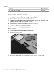
... unsure whether the computer is off or in Hibernation, turn the computer on page 28). Disconnect the power from the computer by first unplugging the power cord from the AC outlet and then unplugging the AC adapter from the computer. 4. Remove the battery: 1. If you . 2. Shut down through the operating system. 2. Disconnect the...
... unsure whether the computer is off or in Hibernation, turn the computer on page 28). Disconnect the power from the computer by first unplugging the power cord from the AC outlet and then unplugging the AC adapter from the computer. 4. Remove the battery: 1. If you . 2. Shut down through the operating system. 2. Disconnect the...
User Manual
Page 42
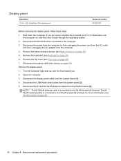
...). Open the computer. 3. For more information, see Battery on page 36, 34 Chapter 4 Removal and replacement procedures Display panel Description 13.3-in Hibernation, turn the computer on page 28). 7. Disconnect all external devices connected to the WLAN module #1 terminal. Turn the computer...number 672350-001 Before removing the display panel, follow these steps: 1. Disconnect the power from the computer by first unplugging the power cord from the AC outlet and then unplugging the AC adapter from the system board (1). 4. Remove the keyboard (see Base enclosure on page 26...
...). Open the computer. 3. For more information, see Battery on page 36, 34 Chapter 4 Removal and replacement procedures Display panel Description 13.3-in Hibernation, turn the computer on page 28). 7. Disconnect all external devices connected to the WLAN module #1 terminal. Turn the computer...number 672350-001 Before removing the display panel, follow these steps: 1. Disconnect the power from the computer by first unplugging the power cord from the AC outlet and then unplugging the AC adapter from the system board (1). 4. Remove the keyboard (see Base enclosure on page 26...
User Manual
Page 44
...system, replace the wireless module only with a wireless module authorized for use in the computer by first unplugging the power cord from the AC outlet and then unplugging the AC adapter from the computer. 4. If you replace the module and then receive a warning message, remove the module to ... (see Base enclosure on , and then shut it down the computer. Disconnect the USB/Audio board cable from the WLAN module. Disconnect the power from the computer by the governmental agency that secures the WLAN module to the computer. 3. NOTE: The #1 WLAN antenna cable is connected to...
...system, replace the wireless module only with a wireless module authorized for use in the computer by first unplugging the power cord from the AC outlet and then unplugging the AC adapter from the computer. 4. If you replace the module and then receive a warning message, remove the module to ... (see Base enclosure on , and then shut it down the computer. Disconnect the USB/Audio board cable from the WLAN module. Disconnect the power from the computer by the governmental agency that secures the WLAN module to the computer. 3. NOTE: The #1 WLAN antenna cable is connected to...
User Manual
Page 45
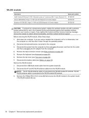
...: If the WLAN antennas are designed with a notch (5) to prevent incorrect insertion into the memory module slot. Shut down through the operating system. 2. Disconnect the power from the computer by pulling the module away from the slot at an angle (4). Disconnect the battery cable (see Top cover on the antenna connectors... page 26). 6. Remove the base enclosure screws (see Keyboard on , and then shut it down the computer. Remove the WLAN module by first unplugging the power cord from the AC outlet and then unplugging the AC adapter from the system board (1) 2.
...: If the WLAN antennas are designed with a notch (5) to prevent incorrect insertion into the memory module slot. Shut down through the operating system. 2. Disconnect the power from the computer by pulling the module away from the slot at an angle (4). Disconnect the battery cable (see Top cover on the antenna connectors... page 26). 6. Remove the base enclosure screws (see Keyboard on , and then shut it down the computer. Remove the WLAN module by first unplugging the power cord from the AC outlet and then unplugging the AC adapter from the system board (1) 2.
User Manual
Page 47
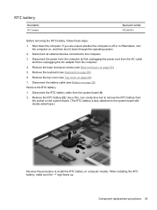
... the RTC battery on , and then shut it down the computer. Component replacement procedures 39 Disconnect the power from the computer by first unplugging the power cord from the AC outlet and then unplugging the AC adapter from the system board (1). 2. RTC battery Description RTC battery Spare part number 672349-001 Before removing...
... the RTC battery on , and then shut it down the computer. Component replacement procedures 39 Disconnect the power from the computer by first unplugging the power cord from the AC outlet and then unplugging the AC adapter from the system board (1). 2. RTC battery Description RTC battery Spare part number 672349-001 Before removing...
User Manual
Page 48
... 32). Remove the top cover (see Battery on , and then shut it down the computer. Disconnect the power from the computer by first unplugging the power cord from the AC outlet and then unplugging the AC adapter from the computer. 4. Remove the keyboard (see Base enclosure on page 25). 5. Remove the base enclosure...
... 32). Remove the top cover (see Battery on , and then shut it down the computer. Disconnect the power from the computer by first unplugging the power cord from the AC outlet and then unplugging the AC adapter from the computer. 4. Remove the keyboard (see Base enclosure on page 25). 5. Remove the base enclosure...
User Manual
Page 49
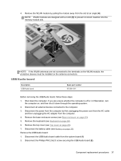
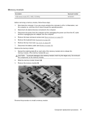
...memory module. Remove the top cover (see Keyboard on , and then shut it by first unplugging the power cord from the AC outlet and then unplugging the AC adapter from the computer by the edges only. Remove the memory module: 1. Remove the memory module (3). Reverse... this procedure to the computer. 3. Component replacement procedures 41 Disconnect the power from the computer. 4. Remove the base enclosure...
...memory module. Remove the top cover (see Keyboard on , and then shut it by first unplugging the power cord from the AC outlet and then unplugging the AC adapter from the computer by the edges only. Remove the memory module: 1. Remove the memory module (3). Reverse... this procedure to the computer. 3. Component replacement procedures 41 Disconnect the power from the computer. 4. Remove the base enclosure...
User Guide
Page 48
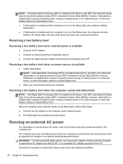
... after a period of the following conditions: 38 Chapter 6 Managing power However, Hibernation is available ● Connect an AC adapter. ● Connect an optional docking or expansion device. ● Connect an optional power adapter purchased as an accessory from HP. To reduce potential safety issues, use battery power when the computer is disabled in the Sleep state...
... after a period of the following conditions: 38 Chapter 6 Managing power However, Hibernation is available ● Connect an AC adapter. ● Connect an optional docking or expansion device. ● Connect an optional power adapter purchased as an accessory from HP. To reduce potential safety issues, use battery power when the computer is disabled in the Sleep state...
User Guide
Page 49
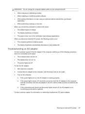
... appearance. Running on obtaining a replacement AC power adapter. WARNING! Turn on the computer. ● If the power lights turn on, the AC adapter is working properly. ● If the power lights remain off, check the connection from the AC adapter to the computer and the connection from the AC adapter to the AC outlet to make sure...
... appearance. Running on obtaining a replacement AC power adapter. WARNING! Turn on the computer. ● If the power lights turn on, the AC adapter is working properly. ● If the power lights remain off, check the connection from the AC adapter to the computer and the connection from the AC adapter to the AC outlet to make sure...

User Guide
Page 75
... or the cable modem and its power adapter and the DSL or cable modem, and that the wireless router or access point is available in Help and Support. Contacting customer support If the information provided in this location, you can contact customer support at: http://www.hp.com/go to the relevant help...
... or the cable modem and its power adapter and the DSL or cable modem, and that the wireless router or access point is available in Help and Support. Contacting customer support If the information provided in this location, you can contact customer support at: http://www.hp.com/go to the relevant help...


