User Manual
Page 6
Power button board ...29 TouchPad button board ...31 Battery ...32 Display panel ...34 WLAN module ...36 USB/Audio board ...37 RTC battery ...39 Hard drive ...40 Memory module ...41 Speakers ...42 System board ...43 Power connector cable ...44 Fan/...50 Updating the BIOS ...50 Determining the BIOS version 51 Downloading a BIOS update 51 Using System Diagnostics ...52 6 Specifications ...53 Computer specifications ...53 13.3-inch display specifications ...53 7 Backup and recovery ...55 Restoring the system ...55 Creating restore media ...55 Performing a system recovery ...56 Using the dedicated...
Power button board ...29 TouchPad button board ...31 Battery ...32 Display panel ...34 WLAN module ...36 USB/Audio board ...37 RTC battery ...39 Hard drive ...40 Memory module ...41 Speakers ...42 System board ...43 Power connector cable ...44 Fan/...50 Updating the BIOS ...50 Determining the BIOS version 51 Downloading a BIOS update 51 Using System Diagnostics ...52 6 Specifications ...53 Computer specifications ...53 13.3-inch display specifications ...53 7 Backup and recovery ...55 Restoring the system ...55 Creating restore media ...55 Performing a system recovery ...56 Using the dedicated...
User Manual
Page 9
1 Product description Category Product Name Processors Chipset Graphics Panel Memory Hard drives Optical drive Audio and video Ethernet Wireless Description HP Folio 13 PC Intel® Core™ i5-2467M 1.6GHz processor SC turbo up to 2.3GHz (3MB L3 cache, dual core 17 W) Intel... wireless module Two WLAN antennas built into display assembly 1 Supports BD and or HD-DVD playback with HD decode, and DX11 support and HDMI support 13.3" high-definition (HD) light-emitting diode (LED), BrightView (1366x768) display; (2.85mm) Shuriken, 200 nits All display assemblies include 2 wireless local ...
1 Product description Category Product Name Processors Chipset Graphics Panel Memory Hard drives Optical drive Audio and video Ethernet Wireless Description HP Folio 13 PC Intel® Core™ i5-2467M 1.6GHz processor SC turbo up to 2.3GHz (3MB L3 cache, dual core 17 W) Intel... wireless module Two WLAN antennas built into display assembly 1 Supports BD and or HD-DVD playback with HD decode, and DX11 support and HDMI support 13.3" high-definition (HD) light-emitting diode (LED), BrightView (1366x768) display; (2.85mm) Shuriken, 200 nits All display assemblies include 2 wireless local ...
User Manual
Page 10
... Bluetooth 4.0 Combo Adapter ● Broadcom 4313GN 802.11b/g/n 1×1 WiFi and 20702 Bluetooth 4.0 Combo Adapter Push-pull insertion/removal HP Multi-Format Digital Media Reader supports the following digital card formats: ● MultiMediaCard ● Secure Digital (SD) Card ● Secure... High-Capacity (SDHC) Card ● Secure Digital Extended Capacity (SDxC) Card ● 3-pin AC power ● Audio-in (mono microphone), supports jack detection ● Audio-out (stereo headphone), supports jack detection ● HDMI version 1.3b supporting 1080p, 1920 ×1080 @ 60Hz ●...
... Bluetooth 4.0 Combo Adapter ● Broadcom 4313GN 802.11b/g/n 1×1 WiFi and 20702 Bluetooth 4.0 Combo Adapter Push-pull insertion/removal HP Multi-Format Digital Media Reader supports the following digital card formats: ● MultiMediaCard ● Secure Digital (SD) Card ● Secure... High-Capacity (SDHC) Card ● Secure Digital Extended Capacity (SDxC) Card ● 3-pin AC power ● Audio-in (mono microphone), supports jack detection ● Audio-out (stereo headphone), supports jack detection ● HDMI version 1.3b supporting 1080p, 1920 ×1080 @ 60Hz ●...
User Manual
Page 17
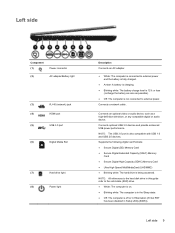
...; Ultra High Speed MultiMediaCard (UHS/MMC) ● Blinking white: The hard drive is also compatible with USB 1.0 and USB 2.0 devices. Connects an optional video or audio device, such as possible). ● Off: The computer is not connected to the solid-state (SSD) drive. ● White: The computer is on. ● Blinking.... ● Blinking white: The battery charge level is 12% or less (recharge the battery as soon as a high-definition television, or any compatible digital or audio component. Connects a network cable.
...; Ultra High Speed MultiMediaCard (UHS/MMC) ● Blinking white: The hard drive is also compatible with USB 1.0 and USB 2.0 devices. Connects an optional video or audio device, such as possible). ● Off: The computer is not connected to the solid-state (SSD) drive. ● White: The computer is on. ● Blinking.... ● Blinking white: The battery charge level is 12% or less (recharge the battery as soon as a high-definition television, or any compatible digital or audio component. Connects a network cable.
User Manual
Page 18
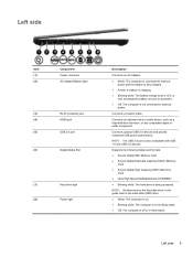
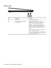
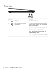
... connected to the Regulatory, Safety and Environmental Notices. Right side Item (1) (2) Component USB 2.0 port Audio-out (headphone) jack/audio-in (microphone) jack Description Connects optional USB devices. Connects optional powered stereo speakers, headphones, earbuds, a headset, or television audio. Also connects an optional headset microphone. WARNING! For additional safety information, refer to the jack...
... connected to the Regulatory, Safety and Environmental Notices. Right side Item (1) (2) Component USB 2.0 port Audio-out (headphone) jack/audio-in (microphone) jack Description Connects optional USB devices. Connects optional powered stereo speakers, headphones, earbuds, a headset, or television audio. Also connects an optional headset microphone. WARNING! For additional safety information, refer to the jack...
User Manual
Page 23
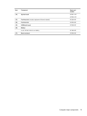
Item Component (12) System board (13) Fan-Heat sink (includes replacement thermal material) (14) Fan-Heat sink (15) USB/Audio board (16) Battery: 6-cell, 59 WHr 5.4AH Li-ion battery (17) Base enclosure Spare part number 672351-001 672352-001 672355-001 672354-001 672358-001 671602-001 672356-001 Computer major components 15
Item Component (12) System board (13) Fan-Heat sink (includes replacement thermal material) (14) Fan-Heat sink (15) USB/Audio board (16) Battery: 6-cell, 59 WHr 5.4AH Li-ion battery (17) Base enclosure Spare part number 672351-001 672352-001 672355-001 672354-001 672358-001 671602-001 672356-001 Computer major components 15
User Manual
Page 26
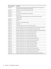
...-Heat sink (includes replacement thermal material) Base enclosure Top cover in black finish (includes power button board and cable and TouchPad and TouchPad cable) USB/Audio board Screw Kit Power connector cable (includes bracket) Thermal pad Rubber Kit (includes two rear corner covers and four rubber feet) 128-GB solid-state...
...-Heat sink (includes replacement thermal material) Base enclosure Top cover in black finish (includes power button board and cable and TouchPad and TouchPad cable) USB/Audio board Screw Kit Power connector cable (includes bracket) Thermal pad Rubber Kit (includes two rear corner covers and four rubber feet) 128-GB solid-state...
User Manual
Page 42
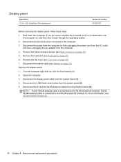
...see Top cover on page 28). 7. Remove the top cover (see Keyboard on page 26). 6. Open the computer. 3. Disconnect the USB/Audio board cable from the computer. 4. Disconnect the power from the computer by first unplugging the power cord from the AC outlet and then unplugging...2. For more information, see Battery on page 32). Remove the base enclosure screws (see Base enclosure on page 25). 5. Display panel Description 13.3-in Hibernation, turn the computer on, and then shut it down the computer. Disconnect the display panel cable from the WLAN module (3). Disconnect the...
...see Top cover on page 28). 7. Remove the top cover (see Keyboard on page 26). 6. Open the computer. 3. Disconnect the USB/Audio board cable from the computer. 4. Disconnect the power from the computer by first unplugging the power cord from the AC outlet and then unplugging...2. For more information, see Battery on page 32). Remove the base enclosure screws (see Base enclosure on page 25). 5. Display panel Description 13.3-in Hibernation, turn the computer on, and then shut it down the computer. Disconnect the display panel cable from the WLAN module (3). Disconnect the...
User Manual
Page 44
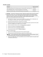
... the WLAN module: 1. Remove the base enclosure screws (see Keyboard on page 26). 6. Remove the keyboard (see Base enclosure on page 28). 7. Disconnect the USB/Audio board cable from the computer. 4. Remove the Phillips PM 2.0×2.5 screw (3) that regulates wireless devices in your country or region. If you replace the module...
... the WLAN module: 1. Remove the base enclosure screws (see Keyboard on page 26). 6. Remove the keyboard (see Base enclosure on page 28). 7. Disconnect the USB/Audio board cable from the computer. 4. Remove the Phillips PM 2.0×2.5 screw (3) that regulates wireless devices in your country or region. If you replace the module...
User Manual
Page 45
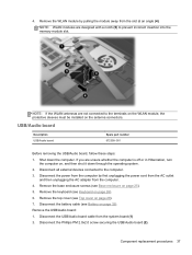
...cover on page 26). 6. Remove the top cover (see Keyboard on page 28). 7. Disconnect the Phillips PM 2.0x2.0 screw securing the USB/Audio board (2). If you are unsure whether the computer is off or in Hibernation, turn the computer on the antenna connectors. Remove the USB.../Audio board: 1. USB/Audio board Description USB/Audio board Spare part number 672358-001 Before removing the USB/Audio board, follow these steps: 1. Remove the base enclosure screws (see Battery on page 25). 5....
...cover on page 26). 6. Remove the top cover (see Keyboard on page 28). 7. Disconnect the Phillips PM 2.0x2.0 screw securing the USB/Audio board (2). If you are unsure whether the computer is off or in Hibernation, turn the computer on the antenna connectors. Remove the USB.../Audio board: 1. USB/Audio board Description USB/Audio board Spare part number 672358-001 Before removing the USB/Audio board, follow these steps: 1. Remove the base enclosure screws (see Battery on page 25). 5....
User Manual
Page 46
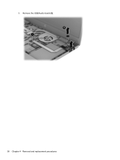
3. Remove the USB/Audio board (3). 38 Chapter 4 Removal and replacement procedures
3. Remove the USB/Audio board (3). 38 Chapter 4 Removal and replacement procedures
User Manual
Page 51
... first unplugging the power cord from the AC outlet and then unplugging the AC adapter from the system board (see Display panel on page 44). 13. Remove the top cover (see WLAN module on page 28). 7. Remove the hard drive (see Speakers on page 40). 10. System board ...thermal material. Remove the speaker (see Hard drive on page 42). 12. Remove the USB/Audio and cable (see Display panel on page 40). ● USB/Audio (see USB/Audio) ● Display panel cable (see USB/Audio). Disconnect all external devices connected to the computer. 3. If you are removed from the ...
... first unplugging the power cord from the AC outlet and then unplugging the AC adapter from the system board (see Display panel on page 44). 13. Remove the top cover (see WLAN module on page 28). 7. Remove the hard drive (see Speakers on page 40). 10. System board ...thermal material. Remove the speaker (see Hard drive on page 42). 12. Remove the USB/Audio and cable (see Display panel on page 40). ● USB/Audio (see USB/Audio) ● Display panel cable (see USB/Audio). Disconnect all external devices connected to the computer. 3. If you are removed from the ...
User Manual
Page 64
... Using the dedicated recovery partition When using the dedicated recovery partition, there is an option to back up pictures, music and other audio, videos and movies, recorded TV shows, documents, spreadsheets and presentations, e-mails, Internet favorites and settings during this computer, you...For software not provided with this process. 56 Chapter 7 Backup and recovery Select Start > All Programs > Security and Protection > HP Recovery Manager > HP Recovery Media Creation. 2. A system restore should be prompted to continue the backup creation process. NOTE: If you are creating recovery...
... Using the dedicated recovery partition When using the dedicated recovery partition, there is an option to back up pictures, music and other audio, videos and movies, recorded TV shows, documents, spreadsheets and presentations, e-mails, Internet favorites and settings during this computer, you...For software not provided with this process. 56 Chapter 7 Backup and recovery Select Start > All Programs > Security and Protection > HP Recovery Manager > HP Recovery Media Creation. 2. A system restore should be prompted to continue the backup creation process. NOTE: If you are creating recovery...
User Manual
Page 72
...left-side 9 lights 7 rear 8 right-side 10 TouchPad 8 computer feet locations 24 removal 24 spare part number 24 computer major components 13 computer part number 24 computer specifications 53 connectors, service considerations 19 D Digital Media Slot, identifying 9 display components 4 specifications 53 display ... removal 40 spare part numbers 14, 16, 40 HDMI port 9 headphone (audio-out) jack 10 heat sink spare part number 15, 18 HP Recovery Manager 56 I Intel Rapid Start Technology 5 J jacks audio-in (microphone) 10 audio-out (headphone) 10 network 9 RJ-45 (network) 9 K key components ...
...left-side 9 lights 7 rear 8 right-side 10 TouchPad 8 computer feet locations 24 removal 24 spare part number 24 computer major components 13 computer part number 24 computer specifications 53 connectors, service considerations 19 D Digital Media Slot, identifying 9 display components 4 specifications 53 display ... removal 40 spare part numbers 14, 16, 40 HDMI port 9 headphone (audio-out) jack 10 heat sink spare part number 15, 18 HP Recovery Manager 56 I Intel Rapid Start Technology 5 J jacks audio-in (microphone) 10 audio-out (headphone) 10 network 9 RJ-45 (network) 9 K key components ...
User Manual
Page 73
keyboard product description 2 removal 26 spare part numbers 13, 18, 26 keys Action 6 esc 6 fn 6 Windows applications 6 Windows logo 6 L left-side components 9 light components 7 lights battery 9 caps lock 7 hard drive 9 mute 7... part number 14, 18 power cord set requirements 61 spare part numbers 16, 17 power light 7 power requirements, product description 2 processor, product description 1 product description audio 1 chipset 1 display panel 1 Ethernet 1 external media cards 2 graphics 1 hard drives 1 keyboard 2 memory module 1 microphone 1 operating system 2 optical drive 1 pointing device 2 ...
keyboard product description 2 removal 26 spare part numbers 13, 18, 26 keys Action 6 esc 6 fn 6 Windows applications 6 Windows logo 6 L left-side components 9 light components 7 lights battery 9 caps lock 7 hard drive 9 mute 7... part number 14, 18 power cord set requirements 61 spare part numbers 16, 17 power light 7 power requirements, product description 2 processor, product description 1 product description audio 1 chipset 1 display panel 1 Ethernet 1 external media cards 2 graphics 1 hard drives 1 keyboard 2 memory module 1 microphone 1 operating system 2 optical drive 1 pointing device 2 ...
User Manual
Page 74
... removal 31 spare part number 14, 31 TouchPad components 8 TouchPad light 8 TouchPad on/off button 8 TouchPad zone 8 transporting guidelines 22 U USB ports, identifying 9, 10 USB/Audio board 15 spare part number 18 using system restore 60 V vent location 8 vents 11 video, product description 1 W warranty period 24 webcam 4 webcam light, identifying 7 webcam...
... removal 31 spare part number 14, 31 TouchPad components 8 TouchPad light 8 TouchPad on/off button 8 TouchPad zone 8 transporting guidelines 22 U USB ports, identifying 9, 10 USB/Audio board 15 spare part number 18 using system restore 60 V vent location 8 vents 11 video, product description 1 W warranty period 24 webcam 4 webcam light, identifying 7 webcam...
User Guide
Page 6
...Using the keyboard ...27 Using the action keys ...27 Using the hotkeys ...28 5 Multimedia and other features ...29 Using the media activity controls ...29 Audio ...29 Adjusting the volume ...30 Checking audio functions on the computer 30 Intel Wireless Display (select models only 31 Webcam ...31 HDMI ...32 Configuring... audio for HDMI 32 6 Managing power ...33 Initiating Sleep or Hibernation ...34 Initiating and exiting Sleep 34 Initiating and exiting Hibernation 35 Setting password ...
...Using the keyboard ...27 Using the action keys ...27 Using the hotkeys ...28 5 Multimedia and other features ...29 Using the media activity controls ...29 Audio ...29 Adjusting the volume ...30 Checking audio functions on the computer 30 Intel Wireless Display (select models only 31 Webcam ...31 HDMI ...32 Configuring... audio for HDMI 32 6 Managing power ...33 Initiating Sleep or Hibernation ...34 Initiating and exiting Sleep 34 Initiating and exiting Hibernation 35 Setting password ...
User Guide
Page 18
... information, refer to the jack, the computer speakers are disabled. Right side Component (1) USB 2.0 port (2) Audio-out (headphone) jack/audio-in (microphone) jack Description Connects optional USB devices. To reduce the risk of personal injury, adjust the volume...operational only when used with a headphone/microphone unit that has a 4conductor audio connector. 8 Chapter 2 Getting to know your computer Connects optional powered stereo speakers, headphones, earbuds, a headset, or television audio. NOTE: The microphone function is connected to the Regulatory, Safety and ...
... information, refer to the jack, the computer speakers are disabled. Right side Component (1) USB 2.0 port (2) Audio-out (headphone) jack/audio-in (microphone) jack Description Connects optional USB devices. To reduce the risk of personal injury, adjust the volume...operational only when used with a headphone/microphone unit that has a 4conductor audio connector. 8 Chapter 2 Getting to know your computer Connects optional powered stereo speakers, headphones, earbuds, a headset, or television audio. NOTE: The microphone function is connected to the Regulatory, Safety and ...
User Guide
Page 19
...white: The battery charge level is 12% or less (recharge the battery as soon as a high-definition television, or any compatible digital or audio device. Connects optional USB 3.0 devices and provide enhanced USB power performance. Supports the following digital card formats: ● Secure Digital (SD) ...MultiMediaCard (UHS/MMC) ● Blinking white: The hard drive is also compatible with USB 1.0 and USB 2.0 devices. Connects an optional video or audio device, such as possible). ● Off: The computer is not connected to the solid-state (SSD) drive. ● White: The computer is...
...white: The battery charge level is 12% or less (recharge the battery as soon as a high-definition television, or any compatible digital or audio device. Connects optional USB 3.0 devices and provide enhanced USB power performance. Supports the following digital card formats: ● Secure Digital (SD) ...MultiMediaCard (UHS/MMC) ● Blinking white: The hard drive is also compatible with USB 1.0 and USB 2.0 devices. Connects an optional video or audio device, such as possible). ● Off: The computer is not connected to the solid-state (SSD) drive. ● White: The computer is...
User Guide
Page 30
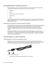
Bluetooth and Internet Connection Sharing (ICS) HP does not recommend setting up a personal area network (PAN) of Bluetooth devices. The strength of Bluetooth is a limitation of Bluetooth and the Windows operating system. ... information on one computer with Bluetooth as a host and using it as the following: ● Computers ● Phones ● Imaging devices (cameras and printers) ● Audio devices ● Mouse Bluetooth devices provide peer-to a local area network (LAN) requires an 8-pin, RJ-45 network cable (purchased separately). To connect the network...
Bluetooth and Internet Connection Sharing (ICS) HP does not recommend setting up a personal area network (PAN) of Bluetooth devices. The strength of Bluetooth is a limitation of Bluetooth and the Windows operating system. ... information on one computer with Bluetooth as a host and using it as the following: ● Computers ● Phones ● Imaging devices (cameras and printers) ● Audio devices ● Mouse Bluetooth devices provide peer-to a local area network (LAN) requires an 8-pin, RJ-45 network cable (purchased separately). To connect the network...


