
Service Manual
Page 8
... 254 Engine test page 254 Formatter test page 254 Interface troubleshooting 255 Communications checks 255 EIO troubleshooting 255 Display-message troubleshooting 257 Status messages 257 Warning messages 257 Error messages 257 Critical-error messages 257 Alphabetical printer messages 258 Numerical printer messages 274 Paper-path troubleshooting 295 Overview 295 Paper-jam recovery 296 Avoiding paper jams...
... 254 Engine test page 254 Formatter test page 254 Interface troubleshooting 255 Communications checks 255 EIO troubleshooting 255 Display-message troubleshooting 257 Status messages 257 Warning messages 257 Error messages 257 Critical-error messages 257 Alphabetical printer messages 258 Numerical printer messages 274 Paper-path troubleshooting 295 Overview 295 Paper-jam recovery 296 Avoiding paper jams...
Service Manual
Page 9
... the environment 307 Print quality problems associated with jams 307 Image defects 308 Image defect tables 311 Repetitive defects troubleshooting 325 Troubleshooting the stacker and the stapler/stacker 326 Overview 326 Initial checks 326 Jam errors 327 Paper transport errors 330 ...Malfunction errors 330 Component errors 331 Printer component locations 332 Main printer parts 332 Printer switches and sensors 336 Printer motors and fans 337 Printer ...
... the environment 307 Print quality problems associated with jams 307 Image defects 308 Image defect tables 311 Repetitive defects troubleshooting 325 Troubleshooting the stacker and the stapler/stacker 326 Overview 326 Initial checks 326 Jam errors 327 Paper transport errors 330 ...Malfunction errors 330 Component errors 331 Printer component locations 332 Main printer parts 332 Printer switches and sensors 336 Printer motors and fans 337 Printer ...
Service Manual
Page 14
... 342 Figure 220. Location of 1,500-sheet paper feeder main parts (2 of printer PCAs 338 Figure 216. Stacker accessory wiring diagram 354 Figure 232. Jam locations 295 Figure 207. HP LaserJet 4300 general timing diagram 358 Figure 236. Sample menu map page 240 Figure 202. ... Figure 237. Duplex accessory wiring diagram 352 Figure 230. Stapler/stacker accessory wiring diagram 355 Figure 233. Right-side assemblies 376 Figure 242. Troubleshooting flowchart (2 of 3 372 Figure 240. Main assemblies (2 of 2 235 Figure 201. Figure 182. 1,500-sheet feeder roller (2 of ...
... 342 Figure 220. Location of 1,500-sheet paper feeder main parts (2 of printer PCAs 338 Figure 216. Stacker accessory wiring diagram 354 Figure 232. Jam locations 295 Figure 207. HP LaserJet 4300 general timing diagram 358 Figure 236. Sample menu map page 240 Figure 202. ... Figure 237. Duplex accessory wiring diagram 352 Figure 230. Stapler/stacker accessory wiring diagram 355 Figure 233. Right-side assemblies 376 Figure 242. Troubleshooting flowchart (2 of 3 372 Figure 240. Main assemblies (2 of 2 235 Figure 201. Figure 182. 1,500-sheet feeder roller (2 of ...

Service Manual
Page 17
... 3. Acoustic ratings 8 Table 6. Paper-handling menu 42 Table 21. System setup submenu 49 Table 25. Printer fans and motors 70 Table 32. Initial troubleshooting checklist 232 Table 38. Common causes of tables Q2431-90912 Table 1. Causes for skewed paper 305 Table 53....Table 11. Resets submenu 247 Table 40. Causes of tray 1 jams 301 Table 45. Stapler stacker submenu 51 Table 26. Cleaning the printer 55 Table 28. Stacker components 104 Table 35. Product configurations 3 Table 2. Power consumption 7 Table 4. Control-panel lights 36 Table 16....
... 3. Acoustic ratings 8 Table 6. Paper-handling menu 42 Table 21. System setup submenu 49 Table 25. Printer fans and motors 70 Table 32. Initial troubleshooting checklist 232 Table 38. Common causes of tables Q2431-90912 Table 1. Causes for skewed paper 305 Table 53....Table 11. Resets submenu 247 Table 40. Causes of tray 1 jams 301 Table 45. Stapler stacker submenu 51 Table 26. Cleaning the printer 55 Table 28. Stacker components 104 Table 35. Product configurations 3 Table 2. Power consumption 7 Table 4. Control-panel lights 36 Table 16....

Service Manual
Page 18
... dots 314 Table 58. Drop outs and character voids 315 Table 59. Loose toner or toner smear 317 Table 62. Printer connection area jam troubleshooting 328 Table 77. Paper-handling accessories 364 Table 83. Paper-pickup assembly 379 Table 95. Paper-feed assembly 383 Table ...313 Table 57. Blurred print 321 Table 72. Transfer assembly 387 Table 103. Component error troubleshooting 331 Table 81. Tray 2 lifter driver assembly 381 Table 97. Skew 319 Table 65. Printer maintenance kit and exchange parts 366 Table 86. Right-side assemblies 376 Table 92. Main assemblies...
... dots 314 Table 58. Drop outs and character voids 315 Table 59. Loose toner or toner smear 317 Table 62. Printer connection area jam troubleshooting 328 Table 77. Paper-handling accessories 364 Table 83. Paper-pickup assembly 379 Table 95. Paper-feed assembly 383 Table ...313 Table 57. Blurred print 321 Table 72. Transfer assembly 387 Table 103. Component error troubleshooting 331 Table 81. Tray 2 lifter driver assembly 381 Table 97. Skew 319 Table 65. Printer maintenance kit and exchange parts 366 Table 86. Right-side assemblies 376 Table 92. Main assemblies...
Service Manual
Page 48
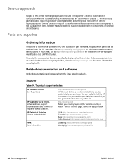
... online at the subassembly level. Related documentation and software Order documentation and software from the HP Services. Service approach Repair of the printer normally begins with the use of the printer's internal diagnostics in conjunction with the troubleshooting procedures that are specifically designed for this manual contains FRU and accessory part numbers. Software drivers...
... online at the subassembly level. Related documentation and software Order documentation and software from the HP Services. Service approach Repair of the printer normally begins with the use of the printer's internal diagnostics in conjunction with the troubleshooting procedures that are specifically designed for this manual contains FRU and accessory part numbers. Software drivers...
Service Manual
Page 153
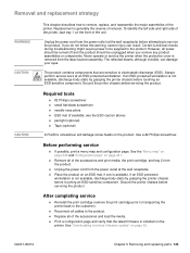
...major assemblies of the accessories and load the media. Certain functional checks during troubleshooting might require power to be unplugged when you do not follow this warning... If an ESD-protected workstation is not available, discharge body static by grasping the printer chassis before attempting to electrostatic discharge (ESD). Removal and replacement strategy WARNING! The ... of the accessories and print media, the print cartridge, and tray 2 from the laser/scanner assembly. Q2431-90912 Chapter 6 Removing and replacing parts 133 Replacement is removed from...
...major assemblies of the accessories and load the media. Certain functional checks during troubleshooting might require power to be unplugged when you do not follow this warning... If an ESD-protected workstation is not available, discharge body static by grasping the printer chassis before attempting to electrostatic discharge (ESD). Removal and replacement strategy WARNING! The ... of the accessories and print media, the print cartridge, and tray 2 from the laser/scanner assembly. Q2431-90912 Chapter 6 Removing and replacing parts 133 Replacement is removed from...

Service Manual
Page 247
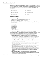
...checks 236 Overview 236 Troubleshooting tools 239 Information pages 239 Menu map 240 Configuration page 241 Supplies status page 242 Embedded Web server 243 Gaining access to the embedded Web server 243 Information tab 244 Settings tab 244 Networking tab 244 Other links 245 Printer Status and Alerts software... Service menu (service PIN codes 249 Service ID 250 Restoring the Service ID 250 Converting the Service ID to an actual date 250 Printer resets and power-on modes 251 Cold reset 251 To perform a cold reset 251 NVRAM initialization 251 To initialize NVRAM 251 Hard-disk...
...checks 236 Overview 236 Troubleshooting tools 239 Information pages 239 Menu map 240 Configuration page 241 Supplies status page 242 Embedded Web server 243 Gaining access to the embedded Web server 243 Information tab 244 Settings tab 244 Networking tab 244 Other links 245 Printer Status and Alerts software... Service menu (service PIN codes 249 Service ID 250 Restoring the Service ID 250 Converting the Service ID to an actual date 250 Printer resets and power-on modes 251 Cold reset 251 To perform a cold reset 251 NVRAM initialization 251 To initialize NVRAM 251 Hard-disk...

Service Manual
Page 248
.../stacker paper path test 328 Paper transport errors 330 Malfunction errors 330 Component errors 331 Printer component locations 332 Main printer parts 332 Printer switches and sensors 336 Printer motors and fans 337 Printer PCAs 338 228 Troubleshooting Q2431-90912 Display-message troubleshooting 257 Status messages 257 Warning messages 257 Error messages 257 Critical-error messages 257...
.../stacker paper path test 328 Paper transport errors 330 Malfunction errors 330 Component errors 331 Printer component locations 332 Main printer parts 332 Printer switches and sensors 336 Printer motors and fans 337 Printer PCAs 338 228 Troubleshooting Q2431-90912 Display-message troubleshooting 257 Status messages 257 Warning messages 257 Error messages 257 Critical-error messages 257...

Service Manual
Page 249
...stacker stapler assembly 344 Stacker and stapler/stacker motors and solenoids 346 Stacker and stapler/stacker PCAs 347 Printer and accessory wiring diagrams 348 HP LaserJet 4200 wiring diagram 348 HP LaserJet 4300 wiring diagram 349 500-sheet feeder wiring diagram 350 1,500-sheet feeder wiring diagram 351 Duplex accessory... wiring diagram 354 Stapler/stacker accessory wiring diagram 355 DC controller connectors diagram 356 General timing diagrams 357 HP LaserJet 4200 general timing diagram 357 HP LaserJet 4300 general timing diagram 358 Q2431-90912 Chapter 7 Troubleshooting 229
...stacker stapler assembly 344 Stacker and stapler/stacker motors and solenoids 346 Stacker and stapler/stacker PCAs 347 Printer and accessory wiring diagrams 348 HP LaserJet 4200 wiring diagram 348 HP LaserJet 4300 wiring diagram 349 500-sheet feeder wiring diagram 350 1,500-sheet feeder wiring diagram 351 Duplex accessory... wiring diagram 354 Stapler/stacker accessory wiring diagram 355 DC controller connectors diagram 356 General timing diagrams 357 HP LaserJet 4200 general timing diagram 357 HP LaserJet 4300 general timing diagram 358 Q2431-90912 Chapter 7 Troubleshooting 229
Service Manual
Page 250
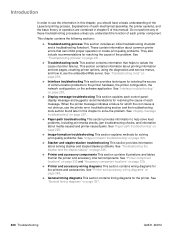
... wiring diagrams for solving print-quality problems. See "Image-formation troubleshooting" on page 231. Do not perform any of these troubleshooting processes unless you should have a basic understanding of the LaserJet printing process. q Troubleshooting tools This section contains information that helps to the printer hardware, the printer configuration, the network configuration, or the software application. q Image...
... wiring diagrams for solving print-quality problems. See "Image-formation troubleshooting" on page 231. Do not perform any of these troubleshooting processes unless you should have a basic understanding of the LaserJet printing process. q Troubleshooting tools This section contains information that helps to the printer hardware, the printer configuration, the network configuration, or the software application. q Image...

Service Manual
Page 251
... the problems that are required to diagnose the cause of the problem. Q2431-90912 Chapter 7 Troubleshooting 231 See "Configuration page" on the printer control panel alerts you to fix the problem. The customer is also responsible for media and ...? q Does the configuration page reveal any troubleshooting procedure, check the following: q Are supply items (for correcting the malfunction. q Use the troubleshooting flowchart to eliminate many possible causes of malfunctions. Troubleshooting process When the printer malfunctions or encounters an unexpected situation, information...
... the problems that are required to diagnose the cause of the problem. Q2431-90912 Chapter 7 Troubleshooting 231 See "Configuration page" on the printer control panel alerts you to fix the problem. The customer is also responsible for media and ...? q Does the configuration page reveal any troubleshooting procedure, check the following: q Are supply items (for correcting the malfunction. q Use the troubleshooting flowchart to eliminate many possible causes of malfunctions. Troubleshooting process When the printer malfunctions or encounters an unexpected situation, information...

Service Manual
Page 252
... 14. Print cartridge q Is the print cartridge installed correctly? Initial troubleshooting checklist The following cold storage)? Initial troubleshooting checklist Environment q Is the printer installed in good condition (no curls, folds, or other flaws)? q Is the printer installed on page 5)? See "Fuser" on page 9. q Was ...room to a warm one to help define the problem(s) quickly. q Is the printer exposed to ammonia gas, such as that you can ask the customer to two hours. 232 Troubleshooting Q2431-90912 See "Supported sizes and weights of media" on page 10 and "...
... 14. Print cartridge q Is the print cartridge installed correctly? Initial troubleshooting checklist The following cold storage)? Initial troubleshooting checklist Environment q Is the printer installed in good condition (no curls, folds, or other flaws)? q Is the printer installed on page 5)? See "Fuser" on page 9. q Was ...room to a warm one to help define the problem(s) quickly. q Is the printer exposed to ammonia gas, such as that you can ask the customer to two hours. 232 Troubleshooting Q2431-90912 See "Supported sizes and weights of media" on page 10 and "...

Service Manual
Page 253
q Remove the printer from the network, and make sure that the failure is associated with the printer before beginning troubleshooting. Check for any non-HP components installed? Table 37. Initial troubleshooting checklist (continued) Miscellaneous q Are any non-HP components (print cartridges, memory modules, and EIO cards) installed in its printers. Q2431-90912 Chapter 7 Troubleshooting 233 Hewlett-Packard recommends the use of HP components in the printer and remove them.
q Remove the printer from the network, and make sure that the failure is associated with the printer before beginning troubleshooting. Check for any non-HP components installed? Table 37. Initial troubleshooting checklist (continued) Miscellaneous q Are any non-HP components (print cartridges, memory modules, and EIO cards) installed in its printers. Q2431-90912 Chapter 7 Troubleshooting 233 Hewlett-Packard recommends the use of HP components in the printer and remove them.

Service Manual
Page 254
...and does a readable message appear? Power on Is the printer on page 254. If the event log does not print, see "Alphabetical printer messages" on page 258 and "Numerical printer messages" on troubleshooting checks. See figure 200 on these two pages highlights the ...is functional Proceed to understand the message and correct the problem. See "Alphabetical printer messages" on page 258 and "Numerical printer messages" on page 236. Troubleshooting flowchart (1 of 2) 234 Troubleshooting Q2431-90912 Event log Print an event log. Control-Panel display Does the message...
...and does a readable message appear? Power on Is the printer on page 254. If the event log does not print, see "Alphabetical printer messages" on page 258 and "Numerical printer messages" on troubleshooting checks. See figure 200 on these two pages highlights the ...is functional Proceed to understand the message and correct the problem. See "Alphabetical printer messages" on page 258 and "Numerical printer messages" on page 236. Troubleshooting flowchart (1 of 2) 234 Troubleshooting Q2431-90912 Event log Print an event log. Control-Panel display Does the message...

Service Manual
Page 255
...Image defects corrected After meeting print quality requirements, go to step 5. See "Alphabetical printer messages" on page 258 and/or "Numerical printer messages" on page 274 and/or "Image-formation troubleshooting" on page 306. NO Perform corrective actions Repeat control-panel error message actions ... Image defects Compare the images with the sample defects in the image defect tables. If error messages appear on page 274. Troubleshooting flowchart (continued) Information pages Can you try to step 6. Evaluate the configuration page After evaluating the configuration page, go to...
...Image defects corrected After meeting print quality requirements, go to step 5. See "Alphabetical printer messages" on page 258 and/or "Numerical printer messages" on page 274 and/or "Image-formation troubleshooting" on page 306. NO Perform corrective actions Repeat control-panel error message actions ... Image defects Compare the images with the sample defects in the image defect tables. If error messages appear on page 274. Troubleshooting flowchart (continued) Information pages Can you try to step 6. Evaluate the configuration page After evaluating the configuration page, go to...

Service Manual
Page 256
...operating properly, the next troubleshooting step is to visually ...is in the troubleshooting process so ...printer functions should be used to spin briefly after the printer...printer control panel is blank ... the printer is not...into the printer. See "Power supply" on the printer power. Place...printer control-panel display is blank, but the main cooling fan runs briefly after the printer...printer operation, the main cooling fan begins to help locate printer errors. 236 Troubleshooting Q2431-90912 It is important to have the printer control panel functional as soon as the printer...
...operating properly, the next troubleshooting step is to visually ...is in the troubleshooting process so ...printer functions should be used to spin briefly after the printer...printer control panel is blank ... the printer is not...into the printer. See "Power supply" on the printer power. Place...printer control-panel display is blank, but the main cooling fan runs briefly after the printer...printer operation, the main cooling fan begins to help locate printer errors. 236 Troubleshooting Q2431-90912 It is important to have the printer control panel functional as soon as the printer...

Service Manual
Page 257
... functional (24V, 5V, and 3.3V are being generated). Q2431-90912 Chapter 7 Troubleshooting 237 Table 38. Replace the DC controller. Measure the voltage at the outlet. Measure the resistance between the two terminals of An operational fan indicates the following: the printer) does not turn on defect or blank display Problem Action The...
... functional (24V, 5V, and 3.3V are being generated). Q2431-90912 Chapter 7 Troubleshooting 237 Table 38. Replace the DC controller. Measure the voltage at the outlet. Measure the resistance between the two terminals of An operational fan indicates the following: the printer) does not turn on defect or blank display Problem Action The...
Service Manual
Page 259
...or flash DIMM if those memory accessories are discussed in detail in the printer memory. q Usage page: The usage page is only available if an optional hard disk is installed. Chapter 7 Troubleshooting 239 For more information, see "Control-panel menus" on the ramdisk ...are installed. Print a configuration page before servicing the printer to scroll through the menus that can be printed before replacing the formatter assembly. q File directory: This page provides information about control panel menus, see the HP LaserJet 4200/4300 Use Guide. Press the DOWN ARROW ( ) ...
...or flash DIMM if those memory accessories are discussed in detail in the printer memory. q Usage page: The usage page is only available if an optional hard disk is installed. Chapter 7 Troubleshooting 239 For more information, see "Control-panel menus" on the ramdisk ...are installed. Print a configuration page before servicing the printer to scroll through the menus that can be printed before replacing the formatter assembly. q File directory: This page provides information about control panel menus, see the HP LaserJet 4200/4300 Use Guide. Press the DOWN ARROW ( ) ...

Service Manual
Page 260
Use the UP ARROW ( ) button or the DOWN ARROW ( ) button to scroll to help navigate the printer submenus and select configuration settings. Figure 201. Sample menu map page 240 Troubleshooting Q2431-90912 Menu map Use the menu map to MENU MAP, and then press the SELECT ( ) button. Printing a menu map is very helpful when you are changing numerous printer settings. 1. Use the UP ARROW ( ) button or the DOWN ARROW ( ) button to scroll to open the menus. 2. Press the SELECT ( ) button to INFORMATION, and then press the SELECT ( ) button. 3.
Use the UP ARROW ( ) button or the DOWN ARROW ( ) button to scroll to help navigate the printer submenus and select configuration settings. Figure 201. Sample menu map page 240 Troubleshooting Q2431-90912 Menu map Use the menu map to MENU MAP, and then press the SELECT ( ) button. Printing a menu map is very helpful when you are changing numerous printer settings. 1. Use the UP ARROW ( ) button or the DOWN ARROW ( ) button to scroll to open the menus. 2. Press the SELECT ( ) button to INFORMATION, and then press the SELECT ( ) button. 3.


