Service Manual
Page 6
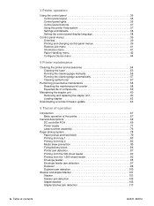
...Loading staples 62 Downloading a remote firmware update 63 5 Theory of operation Introduction 67 Basic operation of the printer 67 General descriptions 69 DC controller PCA 69 Power supply 71 Laser/scanner assembly 76 Paper pickup system 78 Paper pickup and feed block 79 Printing from tray 1 80 Printing ...from tray 2 82 Media skew prevention 85 Fixing/delivery block 86 Printer jam detection 87 Printing from the 500-sheet...
...Loading staples 62 Downloading a remote firmware update 63 5 Theory of operation Introduction 67 Basic operation of the printer 67 General descriptions 69 DC controller PCA 69 Power supply 71 Laser/scanner assembly 76 Paper pickup system 78 Paper pickup and feed block 79 Printing from tray 1 80 Printing ...from tray 2 82 Media skew prevention 85 Fixing/delivery block 86 Printer jam detection 87 Printing from the 500-sheet...
Service Manual
Page 7
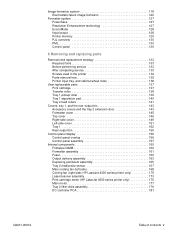
...replacement strategy 133 Required tools 133 Before performing service 133 After completing service 133 Screws used in the printer 134 Parts-removal tree 135 Printer input tray, and cabinet wheel locks 136 User-replaceable parts 137 Print cartridge 137 Transfer roller 138 ... Tray 2 media-size sensor 167 Main cooling fan (left side 168 Cooling fan (right side; HP LaserJet 4300 series printer only 170 Laser/scanner assembly 173 Print-cartridge motor (HP LaserJet 4300 series printer only 175 Main motor 177 Tray 2 lifter-drive assembly 179 DC controller PCA 181 Q2431-90912 Table...
...replacement strategy 133 Required tools 133 Before performing service 133 After completing service 133 Screws used in the printer 134 Parts-removal tree 135 Printer input tray, and cabinet wheel locks 136 User-replaceable parts 137 Print cartridge 137 Transfer roller 138 ... Tray 2 media-size sensor 167 Main cooling fan (left side 168 Cooling fan (right side; HP LaserJet 4300 series printer only 170 Laser/scanner assembly 173 Print-cartridge motor (HP LaserJet 4300 series printer only 175 Main motor 177 Tray 2 lifter-drive assembly 179 DC controller PCA 181 Q2431-90912 Table...

Service Manual
Page 11
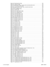
... 20. Stacker driver PCA block diagram 103 Figure 34. Staple mode timing diagram 112 Figure 44. Staple level detection 116 Figure 50. Printer physical dimensions 6 Figure 2. Replacing the stapler unit (1 of 6 111 Figure 41. Loading staples in the staple cartridge (stapler/stacker ...DC controller PCA block diagram 69 Figure 7. Fuser components 71 Figure 9. High-voltage circuit block diagram 73 Figure 11. Laser/scanner assembly 76 Figure 13. Printer paper pickup and feed block diagram 78 Figure 15. Paper pickup/feed and fuser/delivery block diagram 79 Figure 16. ...
... 20. Stacker driver PCA block diagram 103 Figure 34. Staple mode timing diagram 112 Figure 44. Staple level detection 116 Figure 50. Printer physical dimensions 6 Figure 2. Replacing the stapler unit (1 of 6 111 Figure 41. Loading staples in the staple cartridge (stapler/stacker ...DC controller PCA block diagram 69 Figure 7. Fuser components 71 Figure 9. High-voltage circuit block diagram 73 Figure 11. Laser/scanner assembly 76 Figure 13. Printer paper pickup and feed block diagram 78 Figure 15. Paper pickup/feed and fuser/delivery block diagram 79 Figure 16. ...
Service Manual
Page 12
...drum 125 Figure 57. Fuser (2 of 6 152 Figure 87. Duplexing pendulum assembly (2 of 5 171 Figure 115. Cooling fan (HP LaserJet 4300 series only; 3 of 2 166 Figure 106. Tray 2 feed rollers (1 of 2 151 Figure 85. Left-side cover (2 ...Laser/scanner (1 of 4 173 x List of 4 169 Figure 112. Top cover (3 of 4 168 Figure 109. Main cooling fan (1 of 5 147 Figure 77. Cooling fan (HP LaserJet 4300 series only; 1 of 5 172 Figure 117. Cooling fan (HP LaserJet 4300 series only; 5 of 5 170 Figure 113. Location of 4 144 Figure 73. Accessory covers (4 of printer...
...drum 125 Figure 57. Fuser (2 of 6 152 Figure 87. Duplexing pendulum assembly (2 of 5 171 Figure 115. Cooling fan (HP LaserJet 4300 series only; 3 of 2 166 Figure 106. Tray 2 feed rollers (1 of 2 151 Figure 85. Left-side cover (2 ...Laser/scanner (1 of 4 173 x List of 4 169 Figure 112. Top cover (3 of 4 168 Figure 109. Main cooling fan (1 of 5 147 Figure 77. Cooling fan (HP LaserJet 4300 series only; 1 of 5 172 Figure 117. Cooling fan (HP LaserJet 4300 series only; 5 of 5 170 Figure 113. Location of 4 144 Figure 73. Accessory covers (4 of printer...
Service Manual
Page 40
...Standard according to hazardous radiation. 20 Printer description Q2431-90912 The printer is completely confined within protective housings and external covers, the laser beam cannot escape during any phase of 1968. Because radiation emitted inside the printer is certified as possible with a ...obtained by removing as much toner as a "Class 1" laser product under the U.S. Compliance is best cleaned by contacting HP at the http://www.hp.com/go/msds website. Laser safety Do not open the laser scanner assembly. Additional information The print cartridge Material Safety Data Sheet...
...Standard according to hazardous radiation. 20 Printer description Q2431-90912 The printer is completely confined within protective housings and external covers, the laser beam cannot escape during any phase of 1968. Because radiation emitted inside the printer is certified as possible with a ...obtained by removing as much toner as a "Class 1" laser product under the U.S. Compliance is best cleaned by contacting HP at the http://www.hp.com/go/msds website. Laser safety Do not open the laser scanner assembly. Additional information The print cartridge Material Safety Data Sheet...

Service Manual
Page 85
5 Theory of operation Q2431-90912 Contents Introduction 67 Basic operation of the printer 67 Printer operating sequence 67 Control system overview 68 Pickup and feed system overview 68 Laser/scanner system overview 68 Image formation system overview 68 General descriptions 69 DC controller PCA 69 Motor and fan control 70 Power supply 71 Fuser-control...
5 Theory of operation Q2431-90912 Contents Introduction 67 Basic operation of the printer 67 Printer operating sequence 67 Control system overview 68 Pickup and feed system overview 68 Laser/scanner system overview 68 Image formation system overview 68 General descriptions 69 DC controller PCA 69 Motor and fan control 70 Power supply 71 Fuser-control...
Service Manual
Page 87
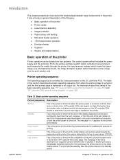
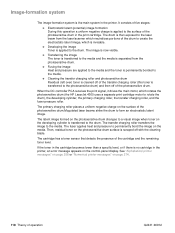
... image formation system (which consists of the basic operating sequence, see "HP LaserJet 4200 general timing diagram" on page 357 and "HP LaserJet 4300 general timing diagram" on the controlpanel display. It also provides a general description of the following: q Basic operation of the printer q Power supply q Laser/scanner assembly q Image formation q Paper pickup and feeding q 500-sheet feeder...
... image formation system (which consists of the basic operating sequence, see "HP LaserJet 4200 general timing diagram" on page 357 and "HP LaserJet 4300 general timing diagram" on the controlpanel display. It also provides a general description of the following: q Basic operation of the printer q Power supply q Laser/scanner assembly q Image formation q Paper pickup and feeding q 500-sheet feeder...
Service Manual
Page 88
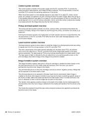
...be seen on and off various solenoids, motors, and other printer components needed to turn on the drum). The photosensitive drum (in the print cartridge to the back of the laser/scanner assembly are the laser driver PCA, the scanner motor and a six-sided mirror. The transfer roller applies a...formation systems. The microprocessor on the the photosensitive drum to the media. The media then passes through the printer, and deliver the media to the media. The laser/scanner PCA converts these data signals into and through the fuser where heat and pressure are used to permanently ...
...be seen on and off various solenoids, motors, and other printer components needed to turn on the drum). The photosensitive drum (in the print cartridge to the back of the laser/scanner assembly are the laser driver PCA, the scanner motor and a six-sided mirror. The transfer roller applies a...formation systems. The microprocessor on the the photosensitive drum to the media. The media then passes through the printer, and deliver the media to the media. The laser/scanner PCA converts these data signals into and through the fuser where heat and pressure are used to permanently ...
Service Manual
Page 89
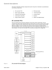
... and feed assembly q Laser/scanner assembly q Image formation system q 500-sheet feeder q 1,500-sheet feeder q envelope feeder q Duplexer q Stacker and stapler/stacker DC controller PCA The DC controller PCA controls the operation of operation 69 The DC controller PCA starts printer operation when the printer power is provided about the following components. HP LaserJet 4300 only Figure 6.
... and feed assembly q Laser/scanner assembly q Image formation system q 500-sheet feeder q 1,500-sheet feeder q envelope feeder q Duplexer q Stacker and stapler/stacker DC controller PCA The DC controller PCA controls the operation of operation 69 The DC controller PCA starts printer operation when the printer power is provided about the following components. HP LaserJet 4300 only Figure 6.
Service Manual
Page 93
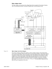
... primary charging voltage (bias) applies a uniform negative charge to the primary charging roller, the developing cylinder, the transfer charging roller, and the pressure roller. The laser/ scanner assembly generates the electrostatic image on the power supply. The primary charging dc negative voltage and the primary charging ac bias. High-voltage circuit The...
... primary charging voltage (bias) applies a uniform negative charge to the primary charging roller, the developing cylinder, the transfer charging roller, and the pressure roller. The laser/ scanner assembly generates the electrostatic image on the power supply. The primary charging dc negative voltage and the primary charging ac bias. High-voltage circuit The...
Service Manual
Page 94
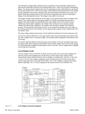
... circuit block diagram 74 Theory of fuser biases. The developing voltage (bias) causes the toner to adhere to the electrostatic image that the laser/scanner assembly created on the photosensitive drum to the media). The developing dc negative bias and the developing ac bias. The transfer voltage (bias...vdc voltage is applied to clean residual toner off of fuser bias. For the HP LaserJet 4300 there are generated by the sub high-voltage circuit on the media from the power source (the wall receptacle the printer's power cord is used by the high-voltage circuit on the power supply....
... circuit block diagram 74 Theory of fuser biases. The developing voltage (bias) causes the toner to adhere to the electrostatic image that the laser/scanner assembly created on the photosensitive drum to the media). The developing dc negative bias and the developing ac bias. The transfer voltage (bias...vdc voltage is applied to clean residual toner off of fuser bias. For the HP LaserJet 4300 there are generated by the sub high-voltage circuit on the media from the power source (the wall receptacle the printer's power cord is used by the high-voltage circuit on the power supply....
Service Manual
Page 96
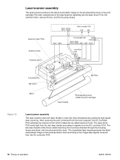
... the photosensitive drum in the print cartridge.The main components of operation Q2431-90912 Scanner motor PCA Scanner motor Scanner mirror Focusing lens BD mirror Mirror BD PCA Laser beams Photosensitive drum (inside the print cartridge) Figure 12. Laser/scanner assembly The laser/scanner produces the latent electrostatic image on the photosensitive drum according to the image data...
... the photosensitive drum in the print cartridge.The main components of operation Q2431-90912 Scanner motor PCA Scanner motor Scanner mirror Focusing lens BD mirror Mirror BD PCA Laser beams Photosensitive drum (inside the print cartridge) Figure 12. Laser/scanner assembly The laser/scanner produces the latent electrostatic image on the photosensitive drum according to the image data...
Service Manual
Page 97
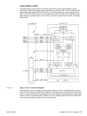
... 5mm down the vertical edges and 8mm at the top and bottom) Q2431-90912 Chapter 5 Theory of operation 77 Figure 13. Laser/scanner control The laser/scanner control circuit on the laser driver PCA turns the laser diodes on an off . The DC controller PCA sends image data signals VD01/VD01,VD02, and /VD02 and the...
... 5mm down the vertical edges and 8mm at the top and bottom) Q2431-90912 Chapter 5 Theory of operation 77 Figure 13. Laser/scanner control The laser/scanner control circuit on the laser driver PCA turns the laser diodes on an off . The DC controller PCA sends image data signals VD01/VD01,VD02, and /VD02 and the...
Service Manual
Page 99
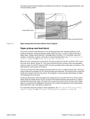
... PCA detects that take place in the pickup/feed block, see "HP LaserJet 4200 general timing diagram" on page 357 and "HP LaserJet 4300 general timing diagram" on page 358. The feed roller moves the media further into the printer. For information about the locations of switches, sensors, and motors in... is activated (SL101) and the pickup arm descends. Fuser/delivery block Figure 15. When the print command is turned on . The laser/scanner motor power is received from being fed all at one time. Paper pickup/feed block Paper pickup/feed and fuser/delivery block diagram Paper...
... PCA detects that take place in the pickup/feed block, see "HP LaserJet 4200 general timing diagram" on page 357 and "HP LaserJet 4300 general timing diagram" on page 358. The feed roller moves the media further into the printer. For information about the locations of switches, sensors, and motors in... is activated (SL101) and the pickup arm descends. Fuser/delivery block Figure 15. When the print command is turned on . The laser/scanner motor power is received from being fed all at one time. Paper pickup/feed block Paper pickup/feed and fuser/delivery block diagram Paper...
Service Manual
Page 100
... registration assembly, where its skew is activated. Figure 16. When the DC controller PCA receives the print command, the printer starts the initial rotation phase. (This consists of main motor warm-up, scanner motor warm-up, high-voltage control sequence and fuser warm-up.) When the initial rotation phase ends, the tray...
... registration assembly, where its skew is activated. Figure 16. When the DC controller PCA receives the print command, the printer starts the initial rotation phase. (This consists of main motor warm-up, scanner motor warm-up, high-voltage control sequence and fuser warm-up.) When the initial rotation phase ends, the tray...

Service Manual
Page 102
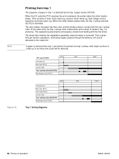
... 82 Theory of operation Q2431-90912 and is corrected. Printing from tray 2 When the DC controller PCA receives print command, the main motor (M101) and scanner motor start rotation. The unnecessary sheets are driven by the main motor rotation.) The tray 2 pickup roller, activated by the separation roller and the media...
... 82 Theory of operation Q2431-90912 and is corrected. Printing from tray 2 When the DC controller PCA receives print command, the main motor (M101) and scanner motor start rotation. The unnecessary sheets are driven by the main motor rotation.) The tray 2 pickup roller, activated by the separation roller and the media...

Service Manual
Page 110
...-feeder driver detect the media size and the presence of the printer begins to the pickup command. When the scanner motor reaches its prescribed speed, the paper-feeder driver receives the pickup command from the 500-sheet feeder The HP LaserJet 4200/4300 series printers support up to two optional 500-sheet feeders. The paperfeeder driver...
...-feeder driver detect the media size and the presence of the printer begins to the pickup command. When the scanner motor reaches its prescribed speed, the paper-feeder driver receives the pickup command from the 500-sheet feeder The HP LaserJet 4200/4300 series printers support up to two optional 500-sheet feeders. The paperfeeder driver...
Service Manual
Page 112
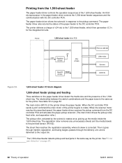
The relationship between the switch combinations and the paper sizes is corrected. When the scanner motor reaches its skew is the same as the printer. The separation roller removes any unnecessary sheets and the media travels to the pickup command. The 1,500-sheet feeder detects ...output bin. Then it goes through the delivery unit; An 8-bit microprocessor in response to the pre-feed sensor (PS102). The printer delivers a charge of the printer drives the paper feeder. Note 1,500-sheet feeder I/O block diagram 1,500-sheet feeder pickup and feeding Three switches on page ...
The relationship between the switch combinations and the paper sizes is corrected. When the scanner motor reaches its skew is the same as the printer. The separation roller removes any unnecessary sheets and the media travels to the pickup command. The 1,500-sheet feeder detects ...output bin. Then it goes through the delivery unit; An 8-bit microprocessor in response to the pre-feed sensor (PS102). The printer delivers a charge of the printer drives the paper feeder. Note 1,500-sheet feeder I/O block diagram 1,500-sheet feeder pickup and feeding Three switches on page ...

Service Manual
Page 116
...separation roller removes any skew. After the main motor initial rotation phase is delivered to rotate. The envelope travels through the printer paper path and is completed, the scanner motor begins to the output bin. Envelope feeder pickup and feed diagram 96 Theory of the rollers in the... printer begins to rotate. The registration assembly corrects any unnecessary envelopes and the envelope travels to drive the pickup roller, feed ...
...separation roller removes any skew. After the main motor initial rotation phase is delivered to rotate. The envelope travels through the printer paper path and is completed, the scanner motor begins to the output bin. Envelope feeder pickup and feed diagram 96 Theory of the rollers in the... printer begins to rotate. The registration assembly corrects any unnecessary envelopes and the envelope travels to drive the pickup roller, feed ...
Service Manual
Page 138
...which is invisable. If the toner in the cartridge becomes lower than a specific level, or if there is no cartridge in the printer. The image is permanently bonded to rotate the drum), the developing cylinder, the primary charging roller, the transfer charging roller, and the... toner is transferred to the media and the media is separated from the laser/scanner which neutralizes portions of the drum to create the electrostatic latent image, which rotates the photosensitive drum (the HP LaserJet 4300 uses a separate print cartridge motor to the media. The transfer charging roller...
...which is invisable. If the toner in the cartridge becomes lower than a specific level, or if there is no cartridge in the printer. The image is permanently bonded to rotate the drum), the developing cylinder, the primary charging roller, the transfer charging roller, and the... toner is transferred to the media and the media is separated from the laser/scanner which neutralizes portions of the drum to create the electrostatic latent image, which rotates the photosensitive drum (the HP LaserJet 4300 uses a separate print cartridge motor to the media. The transfer charging roller...


