Manual
Page 1
MNNM1PI Intel® mini-ITX Motherboard USER'S MANUAL Intel® mini-ITX Motherboard Rev. 1001 * The WEEE marking on the product indicates this product must not be disposed of with user's other household waste and must be handed over to a designated collection point for the recycling of waste electrical and electronic equipment!! * The WEEE marking applies only in European Union's member states.
MNNM1PI Intel® mini-ITX Motherboard USER'S MANUAL Intel® mini-ITX Motherboard Rev. 1001 * The WEEE marking on the product indicates this product must not be disposed of with user's other household waste and must be handed over to a designated collection point for the recycling of waste electrical and electronic equipment!! * The WEEE marking applies only in European Union's member states.
Manual
Page 3
MNNM1PI Motherboard Table of Content Item Checklist 4 Chapter 1 Introduction 5 1-1Considerations Prior to Installation 5 1.2 Features Summary 6 1.3 Motherboard Components 8 Chapter 2 Hardware Installation Process 9 2-1: Installing Memory Module 9 2-2: Connect ribbon cables, cabinet wires, and power supply 10 2-2-1 : I/O Back Panel Introduction 10 2-3: Connectors Introduction & Jumper Setting ...
MNNM1PI Motherboard Table of Content Item Checklist 4 Chapter 1 Introduction 5 1-1Considerations Prior to Installation 5 1.2 Features Summary 6 1.3 Motherboard Components 8 Chapter 2 Hardware Installation Process 9 2-1: Installing Memory Module 9 2-2: Connect ribbon cables, cabinet wires, and power supply 10 2-2-1 : I/O Back Panel Introduction 10 2-3: Connectors Introduction & Jumper Setting ...
Manual
Page 4
Item Checklist The MNNM1PI motherboard I/O Shield Kit CD for motherboard driver & utility Power cable x 1 B4P/S4P Cable x 1 Optional Power Adapter x 1 Introduction * The items listed above are for reference only, and are subject to change without notice. 4
Item Checklist The MNNM1PI motherboard I/O Shield Kit CD for motherboard driver & utility Power cable x 1 B4P/S4P Cable x 1 Optional Power Adapter x 1 Introduction * The items listed above are for reference only, and are subject to change without notice. 4
Manual
Page 5
...to be an unofficial Gigabyte product. 5 Turning on the computer power during the installation process can become damaged as physical harm to the user. 8. Damage as a result of violating the conditions recommended in contact with the motherboard circuit or its power... its components. 5. Damage due to natural disaster, accident or human cause. 2. MNNM1PI Motherboard Chapter 1 Introduction 1-1 Considerations Prior to Installation Preparing Your Computer The motherboard contains numerous delicate electronic circuits and components which can lead to damage to system components...
...to be an unofficial Gigabyte product. 5 Turning on the computer power during the installation process can become damaged as physical harm to the user. 8. Damage as a result of violating the conditions recommended in contact with the motherboard circuit or its power... its components. 5. Damage due to natural disaster, accident or human cause. 2. MNNM1PI Motherboard Chapter 1 Introduction 1-1 Considerations Prior to Installation Preparing Your Computer The motherboard contains numerous delicate electronic circuits and components which can lead to damage to system components...
Manual
Page 7
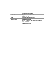
MNNM1PI Motherboard On-Board LAN BIOS Additional Features CPU shutdown when overheat Realtek 8111DL GbE LAN controller Supports WOL, PXE AMI BIOS on 8Mb SPI Flash ROM External Modem wake up Supports S1, S3, S4, S5 under Windows Operating System Wake on LAN (WOL) Supports 4-pin Fan controller 7
MNNM1PI Motherboard On-Board LAN BIOS Additional Features CPU shutdown when overheat Realtek 8111DL GbE LAN controller Supports WOL, PXE AMI BIOS on 8Mb SPI Flash ROM External Modem wake up Supports S1, S3, S4, S5 under Windows Operating System Wake on LAN (WOL) Supports 4-pin Fan controller 7
Manual
Page 8
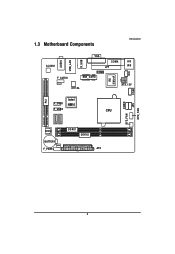
COMD SYS_FAN DIO 1.3 Motherboard Components Introduction PCI AUDIO USB_LAN R_USB ALC662 F_AUDIO VGA COMA KB LPT MS COMB MIN_CARD ITE IT8721F 8111DL ATX_12V COMC JP5 Intel F_USB1 NM10 F_USB2 CPU CPU_FAN BIOS BATTERY F_PANEL DDRII1 DDRII2 ATX 8
COMD SYS_FAN DIO 1.3 Motherboard Components Introduction PCI AUDIO USB_LAN R_USB ALC662 F_AUDIO VGA COMA KB LPT MS COMB MIN_CARD ITE IT8721F 8111DL ATX_12V COMC JP5 Intel F_USB1 NM10 F_USB2 CPU CPU_FAN BIOS BATTERY F_PANEL DDRII1 DDRII2 ATX 8
Manual
Page 9
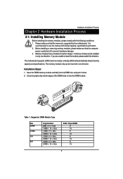
...Steps: 1. Table 1. Before installing or removing memory modules, please make sure that the computer power is supported by the motherboard. Close the plastic clip at both edges of the DIMM slots to prevent hardware damage. 3. Hardware Installation Process Chapter 2... Process 2-1: Installing Memory Module Before installing the memory modules, please comply with similar capacity, specifications and brand. 2. The motherboard supports DDR2 memory module, whereby BIOS will automatically detect memory capacity and specifications. Insert the DIMM memory module vertically into the...
...Steps: 1. Table 1. Before installing or removing memory modules, please make sure that the computer power is supported by the motherboard. Close the plastic clip at both edges of the DIMM slots to prevent hardware damage. 3. Hardware Installation Process Chapter 2... Process 2-1: Installing Memory Module Before installing the memory modules, please comply with similar capacity, specifications and brand. 2. The motherboard supports DDR2 memory module, whereby BIOS will automatically detect memory capacity and specifications. Insert the DIMM memory module vertically into the...
Manual
Page 10
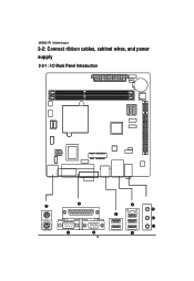
MNNM1PI Motherboard 2-2: Connect ribbon cables, cabinet wires, and power supply 2-2-1 : I/O Back Panel Introduction 10
MNNM1PI Motherboard 2-2: Connect ribbon cables, cabinet wires, and power supply 2-2-1 : I/O Back Panel Introduction 10
Manual
Page 12
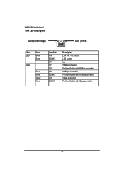
MNNM1PI Motherboard LAN LED Description LED2 (Green/Orange) LED1 (Yellow) Name LED1 LED2 Color Green Green Green Green Yellow Yellow Condition ON BLINK OFF OFF OFF ON BLINK ON BLINK Description LAN Link / no Access LAN Access Idle 10Mbps connection Port identification with 10 Mbps connection 100Mbps connection Port identification with 100Mbps connection 1Gbps connection Port identification with 1Gbps connection 12
MNNM1PI Motherboard LAN LED Description LED2 (Green/Orange) LED1 (Yellow) Name LED1 LED2 Color Green Green Green Green Yellow Yellow Condition ON BLINK OFF OFF OFF ON BLINK ON BLINK Description LAN Link / no Access LAN Access Idle 10Mbps connection Port identification with 10 Mbps connection 100Mbps connection Port identification with 100Mbps connection 1Gbps connection Port identification with 1Gbps connection 12
Manual
Page 14
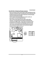
... If the ATX_12V power connector is able to support the system voltage requirements. Please use a power supply that all the components on the motherboard and connect tightly. Before connecting the power connector, please make sure that is not connected, the system will not start . It is ...can lead to an unstable system or a system that is used (350W or greater). Align the power connector with its proper location on the motherboard. If a power supply is unable to start . 1/2/3 ) ATX1/ATX_12V (24-pin/4-pin ATX power connectors) Connector Introduction With the use ...
... If the ATX_12V power connector is able to support the system voltage requirements. Please use a power supply that all the components on the motherboard and connect tightly. Before connecting the power connector, please make sure that is not connected, the system will not start . It is ...can lead to an unstable system or a system that is used (350W or greater). Align the power connector with its proper location on the motherboard. If a power supply is unable to start . 1/2/3 ) ATX1/ATX_12V (24-pin/4-pin ATX power connectors) Connector Introduction With the use ...
Manual
Page 15
MNNM1PI Motherboard 1 12 13 24 Pin No. 1 2 3 4 5 6 7 8 9 10 11 12 Definition 3.3V 3.3V GND +5V GND +5V GND Power Good 5V SB(stand by +5V) +12V +12V(...
MNNM1PI Motherboard 1 12 13 24 Pin No. 1 2 3 4 5 6 7 8 9 10 11 12 Definition 3.3V 3.3V GND +5V GND +5V GND Power Good 5V SB(stand by +5V) +12V +12V(...
Manual
Page 16
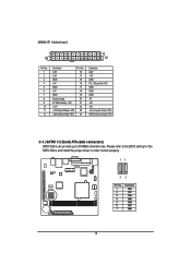
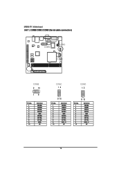
GND NDSR4NRTS4NCTS4NRI4_C- NC COMC 12 COMD 12 9 10 Pin No. 1 2 3 4 5 6 7 8 9 10 Definition NDCD3NRXD3 NTXD3NDTR3GND NDSR3NRTS3NCTS3NRI3_C- GND NDSRBNRTSBNCTSBNRIB- NC 16 NC Pin No. 1 2 3 4 5 6 7 8 9 10 9 10 Definition NDCD4NRXD4 NTXD4NDTR4- MNNM1PI Motherboard 5/6/7 ) COMB/COMC/COMD (Serial cable connectors) COMB COMC COMD COMB 2 10 19 Pin No. 1 2 3 4 5 6 7 8 9 10 Definition NDCDBNRXDB NTXDBNDTRB-
GND NDSR4NRTS4NCTS4NRI4_C- NC COMC 12 COMD 12 9 10 Pin No. 1 2 3 4 5 6 7 8 9 10 Definition NDCD3NRXD3 NTXD3NDTR3GND NDSR3NRTS3NCTS3NRI3_C- GND NDSRBNRTSBNCTSBNRIB- NC 16 NC Pin No. 1 2 3 4 5 6 7 8 9 10 9 10 Definition NDCD4NRXD4 NTXD4NDTR4- MNNM1PI Motherboard 5/6/7 ) COMB/COMC/COMD (Serial cable connectors) COMB COMC COMD COMB 2 10 19 Pin No. 1 2 3 4 5 6 7 8 9 10 Definition NDCDBNRXDB NTXDBNDTRB-

Manual
Page 17
MNNM1PI Motherboard 8 ) JP5 (Power COM selection jumper) 12 9 10 Pin No. 1 2 3 4 5 6 7 8 9 10 Definition IO_12V IO_12V COM_NRIC COM_NRID IO_VCC IO_VCC COM_NRIC COM_NRID NRICNRID- RI Default +5V +5V +12V COM_C Close Close Close Close PIN 9 7_9 pin 5_7 pin 3_5 pin 1_3 pin COM_D Close Close Close Close PIN 9 8_10pin 6_8 pin 4_6 pin 2_4 pin 17
MNNM1PI Motherboard 8 ) JP5 (Power COM selection jumper) 12 9 10 Pin No. 1 2 3 4 5 6 7 8 9 10 Definition IO_12V IO_12V COM_NRIC COM_NRID IO_VCC IO_VCC COM_NRIC COM_NRID NRICNRID- RI Default +5V +5V +12V COM_C Close Close Close Close PIN 9 7_9 pin 5_7 pin 3_5 pin 1_3 pin COM_D Close Close Close Close PIN 9 8_10pin 6_8 pin 4_6 pin 2_4 pin 17
Manual
Page 18
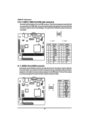
... carefully while you are buying support front audio connector, please contact your chassis must remove 5-6, 9-10 Jumper. In order to work or even damage it. MNNM1PI Motherboard 9/10 ) F_USB1/F_USB2 (Front USB cable connectors) Be careful with the polarity of the front USB connector.
... carefully while you are buying support front audio connector, please contact your chassis must remove 5-6, 9-10 Jumper. In order to work or even damage it. MNNM1PI Motherboard 9/10 ) F_USB1/F_USB2 (Front USB cable connectors) Be careful with the polarity of the front USB connector.
Manual
Page 21
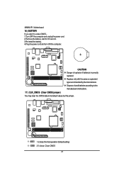
MNNM1PI Motherboard 16 ) BATTERY If you want to its default values by the manufacturer. Dispose of explosion if battery is incorrectly replaced. Replace only with ...
MNNM1PI Motherboard 16 ) BATTERY If you want to its default values by the manufacturer. Dispose of explosion if battery is incorrectly replaced. Replace only with ...
Manual
Page 22
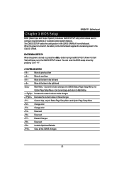
Chapter 3 BIOS Setup MNNM1PI Motherboard BIOS (Basic Input and Output System) includes a CMOS SETUP utility which allows user to configure required settings or to Main Menu Increase the numeric value ... the right hand Main Menu - CONTROL KEYS Move to previous item Move to next item Move to the item in the CMOS SRAM of the motherboard. When the power is turned on the motherboard supplies the necessary power to the CMOS SRAM.
Chapter 3 BIOS Setup MNNM1PI Motherboard BIOS (Basic Input and Output System) includes a CMOS SETUP utility which allows user to configure required settings or to Main Menu Increase the numeric value ... the right hand Main Menu - CONTROL KEYS Move to previous item Move to next item Move to the item in the CMOS SRAM of the motherboard. When the power is turned on the motherboard supplies the necessary power to the CMOS SRAM.
Manual
Page 23
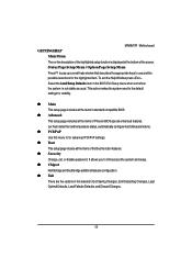
... Help Window press . Select the Load Setup Defaults item in standard compatible BIOS. Advanced This setup page includes all the items of the screen. MNNM1PI Motherboard GETTINGHELP Main Menu The on-line description of the highlighted setup function is displayed at the bottom of Phoenix BIOS special enhanced features. (ex: Auto...
... Help Window press . Select the Load Setup Defaults item in standard compatible BIOS. Advanced This setup page includes all the items of the screen. MNNM1PI Motherboard GETTINGHELP Main Menu The on-line description of the highlighted setup function is displayed at the bottom of Phoenix BIOS special enhanced features. (ex: Auto...
Manual
Page 24
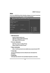
BIOS Information Version: displays the BIOS version. Memory Information Size: The BIOS determines how much available memory is calculated based on the screen. MNNM1PI Motherboard Main Once you set the date. 24 Use arrow keys to select among the items and press to accept or enter the sub-menu. System ...
BIOS Information Version: displays the BIOS version. Memory Information Size: The BIOS determines how much available memory is calculated based on the screen. MNNM1PI Motherboard Main Once you set the date. 24 Use arrow keys to select among the items and press to accept or enter the sub-menu. System ...

Manual
Page 25
... Advanced PCIPnP Boot Security Chipset Exit Advanced Settings WARNING: Setting wrong values in below sections may cause system to configure your system for advanced operation. MNNM1PI Motherboard Advanced About This Section: Advanced With this section, allowing user to malfucntion. CPU Configuration IDE Configuration Super IO Configuration Hardware Health...
... Advanced PCIPnP Boot Security Chipset Exit Advanced Settings WARNING: Setting wrong values in below sections may cause system to configure your system for advanced operation. MNNM1PI Motherboard Advanced About This Section: Advanced With this section, allowing user to malfucntion. CPU Configuration IDE Configuration Super IO Configuration Hardware Health...
Manual
Page 26
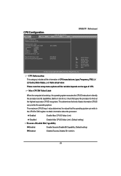
... out the highest input value CPUID recognizes. CPU Configuration BIOS SETUP UTILITY Main Advanced PCIPnP Boot Security Chipset Exit CPU Configuration Module Version: 3F.15 MNNM1PI Motherboard Manufacturer: Intel Intel (R) Atom(TM) CPU K410 Frequency :1.66GHz FSB :666MHz Cache L1 :24KB Cache L2 :512KB Ratio Actual Vaule : 10 @ 1.66GHz Max CPUID Value...
... out the highest input value CPUID recognizes. CPU Configuration BIOS SETUP UTILITY Main Advanced PCIPnP Boot Security Chipset Exit CPU Configuration Module Version: 3F.15 MNNM1PI Motherboard Manufacturer: Intel Intel (R) Atom(TM) CPU K410 Frequency :1.66GHz FSB :666MHz Cache L1 :24KB Cache L2 :512KB Ratio Actual Vaule : 10 @ 1.66GHz Max CPUID Value...


