Manual
Page 3
... Motherboard Components 8 Chapter 2 Hardware Installation Process 9 2-1: Installing Memory Module 9 2-2: Connect ribbon cables, cabinet wires, and power supply 10 2-2-1 : I/O Back Panel Introduction 10 2-3: Connectors Introduction & Jumper Setting 13 Chapter 3 BIOS Setup 22 Main ...24 Advanced 25 CPU Configuration ...26 IDE Configuration ...27 Super IO Configuration ...30 Hardware Health Configuration 33 ACPI Configuration ...36 USB Configuration ...38 PCI/PnP ...40 Boot ...41 Security ...43 Chipset ...45 North Bridge Configuration 46 South Bridge Configuration 47 Onboard Peripheral...
... Motherboard Components 8 Chapter 2 Hardware Installation Process 9 2-1: Installing Memory Module 9 2-2: Connect ribbon cables, cabinet wires, and power supply 10 2-2-1 : I/O Back Panel Introduction 10 2-3: Connectors Introduction & Jumper Setting 13 Chapter 3 BIOS Setup 22 Main ...24 Advanced 25 CPU Configuration ...26 IDE Configuration ...27 Super IO Configuration ...30 Hardware Health Configuration 33 ACPI Configuration ...36 USB Configuration ...38 PCI/PnP ...40 Boot ...41 Security ...43 Chipset ...45 North Bridge Configuration 46 South Bridge Configuration 47 Onboard Peripheral...
Manual
Page 6
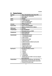
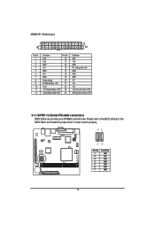
... 1 PCI slot 32-Bit/33MHz Supports 1 mini card slot (PCI-E x1/ USB 2.0) Intel® NM 10 Build in Intel® GMA 3150 Shared system memory up to 384MB Relteak®ALC662 chipset Supports HD 6 channel 1 x 24-pin ATX power connector 1 x 4-pin ATX power connector 2 x SATA connectors 3 x Serial connectors (COM) 1 x front audio connector 2 x USB 2.0 connectors for additional 4 ports by cable 1 x front panel connecctor 1 x DIO panel connecctor 1 x System fan cable...
... 1 PCI slot 32-Bit/33MHz Supports 1 mini card slot (PCI-E x1/ USB 2.0) Intel® NM 10 Build in Intel® GMA 3150 Shared system memory up to 384MB Relteak®ALC662 chipset Supports HD 6 channel 1 x 24-pin ATX power connector 1 x 4-pin ATX power connector 2 x SATA connectors 3 x Serial connectors (COM) 1 x front audio connector 2 x USB 2.0 connectors for additional 4 ports by cable 1 x front panel connecctor 1 x DIO panel connecctor 1 x System fan cable...

Manual
Page 7
MNNM1PI Motherboard On-Board LAN BIOS Additional Features CPU shutdown when overheat Realtek 8111DL GbE LAN controller Supports WOL, PXE AMI BIOS on 8Mb SPI Flash ROM External Modem wake up Supports S1, S3, S4, S5 under Windows Operating System Wake on LAN (WOL) Supports 4-pin Fan controller 7
MNNM1PI Motherboard On-Board LAN BIOS Additional Features CPU shutdown when overheat Realtek 8111DL GbE LAN controller Supports WOL, PXE AMI BIOS on 8Mb SPI Flash ROM External Modem wake up Supports S1, S3, S4, S5 under Windows Operating System Wake on LAN (WOL) Supports 4-pin Fan controller 7
Manual
Page 11
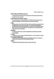
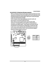
... not support USB controller, please contact OS vendor for possible patch or driver updated. Devices like printer can be connected to Line Out (Front Speaker Out) jack. MIC In The default MIC In jack. Microphone must be connected to Serial port. Line Out (Front Speaker Out) The default Line Out (Front Speaker Out) jack. USB Before you connect your device(s) into USB connector(s), please make sure your device(s) such as USB keyboard, mouse...
... not support USB controller, please contact OS vendor for possible patch or driver updated. Devices like printer can be connected to Line Out (Front Speaker Out) jack. MIC In The default MIC In jack. Microphone must be connected to Serial port. Line Out (Front Speaker Out) The default Line Out (Front Speaker Out) jack. USB Before you connect your device(s) into USB connector(s), please make sure your device(s) such as USB keyboard, mouse...
Manual
Page 14
... a 24-pin ATX power connector, please remove the small cover on the power connector on the motherboard and connect tightly. The ATX_12V power connector mainly supplies power to support the system voltage requirements. If the ATX_12V power connector is unable to all components and devices are properly installed. If you use a power supply that is not connected, the system will not start . Align the power connector with its proper location on the motherboard before plugging in the power cord; Please use a power supply that...
... a 24-pin ATX power connector, please remove the small cover on the power connector on the motherboard and connect tightly. The ATX_12V power connector mainly supplies power to support the system voltage requirements. If the ATX_12V power connector is unable to all components and devices are properly installed. If you use a power supply that is not connected, the system will not start . Align the power connector with its proper location on the motherboard before plugging in the power cord; Please use a power supply that...
Manual
Page 15
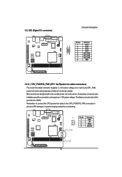
MNNM1PI Motherboard 1 12 13 24 Pin No. 1 2 3 4 5 6 7 8 9 10 11 12 Definition 3.3V 3.3V GND +5V GND +5V GND Power Good 5V SB(stand by +5V) +12V +12V(Only for 24-pin ATX) 3.3V(Only for 24-pin ATX) Pin No. 13 14 15 16 17 18 19 20 21 22 23 24 Definition 3.... GND GND -5V +5V +5V +5V (Only for 24-pin ATX) GND(Only for the SATA 3Gb/s and install the proper driver in order to 300MB/s stransfer rate. Please refer to the BIOS setting for 24-pin ATX) 3/ 4 ) SATAII 1/2 (Serial ATA cable connectors) SATA 3Gb/s can provide up to work properly. 11 77 Pin No. 1 2 3 4 5 6 7 Definition GND TXP ...
MNNM1PI Motherboard 1 12 13 24 Pin No. 1 2 3 4 5 6 7 8 9 10 11 12 Definition 3.3V 3.3V GND +5V GND +5V GND Power Good 5V SB(stand by +5V) +12V +12V(Only for 24-pin ATX) 3.3V(Only for 24-pin ATX) Pin No. 13 14 15 16 17 18 19 20 21 22 23 24 Definition 3.... GND GND -5V +5V +5V +5V (Only for 24-pin ATX) GND(Only for the SATA 3Gb/s and install the proper driver in order to 300MB/s stransfer rate. Please refer to the BIOS setting for 24-pin ATX) 3/ 4 ) SATAII 1/2 (Serial ATA cable connectors) SATA 3Gb/s can provide up to work properly. 11 77 Pin No. 1 2 3 4 5 6 7 Definition GND TXP ...
Manual
Page 19
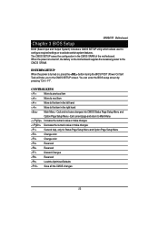
... or system hanging caused by overheating. 1 CPU_FAN Pin No. 1 2 3 4 Definition GND 12V Sense Control SYS_FAN 19 12 ) DIO (Digtal I/O connector) Connector Introduction Pin No. Definition 12 1 2 VCC3 VCC3 3 VCC3 4 VCC3 78 5 ATX_3VSB 6 ATX_3VSB 7 ATX_3VSB 8 GND 13/14 ) CPU_FAN/SYS_FAN (CPU fan/System fan cable connectors) The cooler fan power connector supplies a +12V power voltage via a 3-pin/4-pin(CPU_FAN) power connector and possesses a foolproof connection design. A red power connector wire indicates a positive connection and requires a +12V power voltage.
... or system hanging caused by overheating. 1 CPU_FAN Pin No. 1 2 3 4 Definition GND 12V Sense Control SYS_FAN 19 12 ) DIO (Digtal I/O connector) Connector Introduction Pin No. Definition 12 1 2 VCC3 VCC3 3 VCC3 4 VCC3 78 5 ATX_3VSB 6 ATX_3VSB 7 ATX_3VSB 8 GND 13/14 ) CPU_FAN/SYS_FAN (CPU fan/System fan cable connectors) The cooler fan power connector supplies a +12V power voltage via a 3-pin/4-pin(CPU_FAN) power connector and possesses a foolproof connection design. A red power connector wire indicates a positive connection and requires a +12V power voltage.
Manual
Page 22
Chapter 3 BIOS Setup MNNM1PI Motherboard BIOS (Basic Input and Output System) includes a CMOS SETUP utility which allows user to configure required settings or to the item in the right hand Main Menu - When the power is turned on the motherboard supplies the necessary power to the CMOS SRAM. CONTROL KEYS Move to previous item Move to next item Move to the item in the CMOS SRAM of the motherboard. The CMOS SETUP saves the configuration in the...
Chapter 3 BIOS Setup MNNM1PI Motherboard BIOS (Basic Input and Output System) includes a CMOS SETUP utility which allows user to configure required settings or to the item in the right hand Main Menu - When the power is turned on the motherboard supplies the necessary power to the CMOS SRAM. CONTROL KEYS Move to previous item Move to next item Move to the item in the CMOS SRAM of the motherboard. The CMOS SETUP saves the configuration in the...
Manual
Page 23
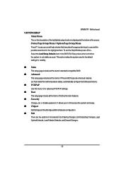
... screen. To exit the Help Window press . Select the Load Setup Defaults item in this menu to use and the possible selections for advanced PCI/PnP settings. Boot This setup page include all the items of Phoenix BIOS special enhanced features. (ex: Auto detect fan and temperature status, automatically configure hard disk parameters.) PCI/PnP Use this selection: Exit Saving Changes, Exit Discarding Changes, Load Optimal Defaults, Load Failsafe Defaults, and Discard Changes. 23 MNNM1PI Motherboard GETTINGHELP Main Menu...
... screen. To exit the Help Window press . Select the Load Setup Defaults item in this menu to use and the possible selections for advanced PCI/PnP settings. Boot This setup page include all the items of Phoenix BIOS special enhanced features. (ex: Auto detect fan and temperature status, automatically configure hard disk parameters.) PCI/PnP Use this selection: Exit Saving Changes, Exit Discarding Changes, Load Optimal Defaults, Load Failsafe Defaults, and Discard Changes. 23 MNNM1PI Motherboard GETTINGHELP Main Menu...
Manual
Page 24
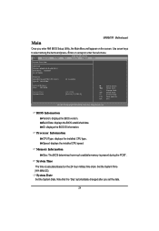
Use arrow keys to select among the items and press to accept or enter the sub-menu. BIOS Information Version: displays the BIOS version. Memory Information Size: The BIOS determines how much available memory is calculated based on the screen. BIOS SETUP UTILITY Main Advanced PCIPnP Boot Security Chipset Exit System Overview AMI BIOS Version: MNM1PIS.f2a/08.00.15 Build Date: 05/20/10 ID: 1IPT9000 Processor Intel(R) Atom(TM) CPU K410 Speed: 1666MHz @ 1.66GHz...
Use arrow keys to select among the items and press to accept or enter the sub-menu. BIOS Information Version: displays the BIOS version. Memory Information Size: The BIOS determines how much available memory is calculated based on the screen. BIOS SETUP UTILITY Main Advanced PCIPnP Boot Security Chipset Exit System Overview AMI BIOS Version: MNM1PIS.f2a/08.00.15 Build Date: 05/20/10 ID: 1IPT9000 Processor Intel(R) Atom(TM) CPU K410 Speed: 1666MHz @ 1.66GHz...
Manual
Page 26
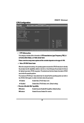
CPU Configuration BIOS SETUP UTILITY Main Advanced PCIPnP Boot Security Chipset Exit CPU Configuration Module Version: 3F.15 MNNM1PI Motherboard Manufacturer: Intel Intel (R) Atom(TM) CPU K410 Frequency :1.66GHz FSB :666MHz Cache L1 :24KB Cache L2 :512KB Ratio Actual Vaule : 10 @ 1.66GHz Max CPUID Value Limit Execute-Disable Bit Capability [Disabled] [Enabled] Select Screen Select Item +- The maximum CPUID input value determines the values that setup menu options will be variable depends...
CPU Configuration BIOS SETUP UTILITY Main Advanced PCIPnP Boot Security Chipset Exit CPU Configuration Module Version: 3F.15 MNNM1PI Motherboard Manufacturer: Intel Intel (R) Atom(TM) CPU K410 Frequency :1.66GHz FSB :666MHz Cache L1 :24KB Cache L2 :512KB Ratio Actual Vaule : 10 @ 1.66GHz Max CPUID Value Limit Execute-Disable Bit Capability [Disabled] [Enabled] Select Screen Select Item +- The maximum CPUID input value determines the values that setup menu options will be variable depends...
Manual
Page 27
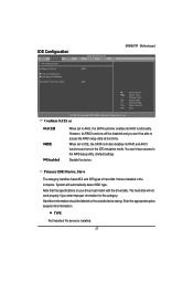
... RAID setup utility at boot time. However, its RAID functions will be disabled and you enter improper information for this information. Enter the appropriate option based on the outside device casing. TYPE Not Installed: No device is installed. 27 IDE Configuration BIOS SETUP UTILITY Main Advanced PCIPnP Boot Security Chipset Exit IDE Configuration Configure SATA as ACHI IDE Disabled When set to IDE, the SATA controller disables its AHCI functionality. Primary IDE Master, Slave The category identifies Serial ATA and IDE types of hard disk that the specifications...
... RAID setup utility at boot time. However, its RAID functions will be disabled and you enter improper information for this information. Enter the appropriate option based on the outside device casing. TYPE Not Installed: No device is installed. 27 IDE Configuration BIOS SETUP UTILITY Main Advanced PCIPnP Boot Security Chipset Exit IDE Configuration Configure SATA as ACHI IDE Disabled When set to IDE, the SATA controller disables its AHCI functionality. Primary IDE Master, Slave The category identifies Serial ATA and IDE types of hard disk that the specifications...
Manual
Page 28
... setting) S.M.A.R.T Mode This option enables/disables support for the two IDE devices (Master and Slave drives) attached to set all current hard disks and it allows the early prediction and warning of Multi-Sector Transfer Mode. Auto: Auto configuration. (Default setting) 28 Disabled: Disable PIO Mode. capability. ARMD: Use ARMD drive is supported by all HDD parameters automatically. Disabled: Disable LBA/Large Mode. Disabled: Disable S.M.A.R.T Mode. Enabled: Enable S.M.A.R.T Mode. The S.M.A.R.T. (Self Monitoring Analysis And Reporting) technology is installed...
... setting) S.M.A.R.T Mode This option enables/disables support for the two IDE devices (Master and Slave drives) attached to set all current hard disks and it allows the early prediction and warning of Multi-Sector Transfer Mode. Auto: Auto configuration. (Default setting) 28 Disabled: Disable PIO Mode. capability. ARMD: Use ARMD drive is supported by all HDD parameters automatically. Disabled: Disable LBA/Large Mode. Disabled: Disable S.M.A.R.T Mode. Enabled: Enable S.M.A.R.T Mode. The S.M.A.R.T. (Self Monitoring Analysis And Reporting) technology is installed...
Manual
Page 34
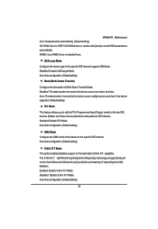
... Function. (Default setting) Hardware Health Function Enabled Enable Hardware Health Function. (Default setting) Disabled Disable Hardware Health Function. CPU FAN Temp. MNNM1PI Motherboard When CPU FAN Mode Setting is set to PWM Manually mode BIOS SETUP UTILITY Main Advanced PCIPnP Boot Security Chipset Exit Hardware Health Configuration CPU FAN Stop Warning System FAN Stop Warning Hardware Health Function CPU FAN Mode Setting CPU FAN PWM Control [Enabled] [Disabled] [Enabled] [PWM Manually mode] [255] System Temperature CPU Temperature CPU FAN Speed System FAN Speed +3.30V...
... Function. (Default setting) Hardware Health Function Enabled Enable Hardware Health Function. (Default setting) Disabled Disable Hardware Health Function. CPU FAN Temp. MNNM1PI Motherboard When CPU FAN Mode Setting is set to PWM Manually mode BIOS SETUP UTILITY Main Advanced PCIPnP Boot Security Chipset Exit Hardware Health Configuration CPU FAN Stop Warning System FAN Stop Warning Hardware Health Function CPU FAN Mode Setting CPU FAN PWM Control [Enabled] [Disabled] [Enabled] [PWM Manually mode] [255] System Temperature CPU Temperature CPU FAN Speed System FAN Speed +3.30V...
Manual
Page 36
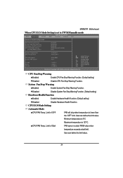
... ACPI v3.0. ACPI Configuration BIOS SETUP UTILITY Main Advanced PCIPnP Boot Security Chipset Exit ACPI Settings Suspend Mode ACPI Version Features ACPI APIC support Resume On RTC Alarm epost Video on Suspend) sleep state. Change Field Tab Select Field F1 General Help F10 Save and Exit ESC Exit v02.61 (C) Copyright 1985-2006, American Megatrends, Inc. Suspend Mode S1 (POS) Enables the system to enter the ACPI S1 (Power on S3 Resume [Auto] [ACPI v3.0] [Enabled] [Disabled] [No] MNNM1PI Motherboard...
... ACPI v3.0. ACPI Configuration BIOS SETUP UTILITY Main Advanced PCIPnP Boot Security Chipset Exit ACPI Settings Suspend Mode ACPI Version Features ACPI APIC support Resume On RTC Alarm epost Video on Suspend) sleep state. Change Field Tab Select Field F1 General Help F10 Save and Exit ESC Exit v02.61 (C) Copyright 1985-2006, American Megatrends, Inc. Suspend Mode S1 (POS) Enables the system to enter the ACPI S1 (Power on S3 Resume [Auto] [ACPI v3.0] [Enabled] [Disabled] [No] MNNM1PI Motherboard...
Manual
Page 38
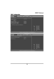
... Setting wrong values in below sections may cause system to malfucntion. CPU Configuration IDE Configuration Super IO Configuration Hardware Health Configuration ACPI Configuration USB Configuration USB Configuration BIOS SETUP UTILITY Main Advanced PCIPnP Boot Security Chipset Exit USB Configuration MNNM1PI Motherboard Module Version USB Device Enabled: 1 Drive Legacy USB Support USB Keyboard Legacy Support USB Mouse Legacy Support USB Storage Device Support 2.24.3-13.4 [Enabled] [Enabled] [Enabled] [Enabled] USB Mass Storage Device...
... Setting wrong values in below sections may cause system to malfucntion. CPU Configuration IDE Configuration Super IO Configuration Hardware Health Configuration ACPI Configuration USB Configuration USB Configuration BIOS SETUP UTILITY Main Advanced PCIPnP Boot Security Chipset Exit USB Configuration MNNM1PI Motherboard Module Version USB Device Enabled: 1 Drive Legacy USB Support USB Keyboard Legacy Support USB Mouse Legacy Support USB Storage Device Support 2.24.3-13.4 [Enabled] [Enabled] [Enabled] [Enabled] USB Mass Storage Device...
Manual
Page 41
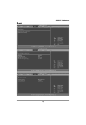
... ESC Exit v02.61 (C) Copyright 1985-2006, American Megatrends, Inc. BIOS SETUP UTILITY Main Advanced PCIPnP Boot Security Chipset Exit Boot Device Priority 1st Boot Priority 2nd Boot Priority 3rd Boot Priority [Removable Dev.] [CD/DVD] [Hard Drive] Select Screen Select Item +- BIOS SETUP UTILITY PCIPnP Boot Security Chipset Exit Boot Settings Configuration Quick Boot Bootup Num-Lock Wait for 'F1' If Error Hit 'DEL' Message Display [Enabled] [On] [Enabled] [Enabled] Select Screen Select Item +-
... ESC Exit v02.61 (C) Copyright 1985-2006, American Megatrends, Inc. BIOS SETUP UTILITY Main Advanced PCIPnP Boot Security Chipset Exit Boot Device Priority 1st Boot Priority 2nd Boot Priority 3rd Boot Priority [Removable Dev.] [CD/DVD] [Hard Drive] Select Screen Select Item +- BIOS SETUP UTILITY PCIPnP Boot Security Chipset Exit Boot Settings Configuration Quick Boot Bootup Num-Lock Wait for 'F1' If Error Hit 'DEL' Message Display [Enabled] [On] [Enabled] [Enabled] Select Screen Select Item +-
Manual
Page 43
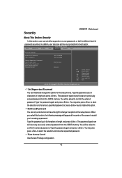
... CMOS memory. User Access Level User Access Privilege configuration. 43 Type the password up to 6 characters in length and press . You may also press to abort the selection and not enter a specified password. You may also press to abort the selection and not enter a specified password or press key to disable this options for the setup menus. BIOS SETUP UTILITY Main Advanced PCIPnP Boot Security Chipset Exit Security Settings Supervisor Password User Password Change Supervisor Password User Access Level Change User Password Clear User Password Password Check : Not Installed...
... CMOS memory. User Access Level User Access Privilege configuration. 43 Type the password up to 6 characters in length and press . You may also press to abort the selection and not enter a specified password. You may also press to abort the selection and not enter a specified password or press key to disable this options for the setup menus. BIOS SETUP UTILITY Main Advanced PCIPnP Boot Security Chipset Exit Security Settings Supervisor Password User Password Change Supervisor Password User Access Level Change User Password Clear User Password Password Check : Not Installed...
Manual
Page 46
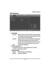
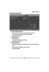
... . Internal Graphics Mode Select Select the amount of system memory used by the internal graphic device. Option available: Enable 1MB, Enable 4MB, and Enabled 8MB. Default setting is Enable, 8MB. Default setting is DVMT Mode. DVMT Mode Select DVMT Mode Selection. North Bridge Configuration BIOS SETUP UTILITY Main Advanced PCIPnP Boot Security Chipset Exit North Bridge Chipset Configuration Internal Graphics Mode Select DVMT Mode Select DVMT/FIXED Memory [Enabled, 8MB] [DVMT Mode] [256MB] MNNM1PI Motherboard Select Screen Select Item +- Change Field...
... . Internal Graphics Mode Select Select the amount of system memory used by the internal graphic device. Option available: Enable 1MB, Enable 4MB, and Enabled 8MB. Default setting is Enable, 8MB. Default setting is DVMT Mode. DVMT Mode Select DVMT Mode Selection. North Bridge Configuration BIOS SETUP UTILITY Main Advanced PCIPnP Boot Security Chipset Exit North Bridge Chipset Configuration Internal Graphics Mode Select DVMT Mode Select DVMT/FIXED Memory [Enabled, 8MB] [DVMT Mode] [256MB] MNNM1PI Motherboard Select Screen Select Item +- Change Field...
Manual
Page 48
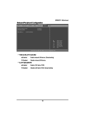
... Help F10 Save and Exit ESC Exit v02.61 (C) Copyright 1985-2006, American Megatrends, Inc. Onboard LAN Controller Enabled Enable onboard LAN device. (Default setting) Disabled Disable onboard LAN device. LAN Option ROM Enabled Enable LAN Option ROM. Disabled Disable LAN Option ROM. (Default setting) 48 Onboard Peripheral Configuration BIOS SETUP UTILITY Main Advanced PCIPnP Boot Security Chipset Exit Onboard LAN Controller LAN Option ROM MAC Address : 00-E0-4C-68-00-12 [Enabled] [Disabled] MNNM1PI Motherboard Select Screen Select Item +-
... Help F10 Save and Exit ESC Exit v02.61 (C) Copyright 1985-2006, American Megatrends, Inc. Onboard LAN Controller Enabled Enable onboard LAN device. (Default setting) Disabled Disable onboard LAN device. LAN Option ROM Enabled Enable LAN Option ROM. Disabled Disable LAN Option ROM. (Default setting) 48 Onboard Peripheral Configuration BIOS SETUP UTILITY Main Advanced PCIPnP Boot Security Chipset Exit Onboard LAN Controller LAN Option ROM MAC Address : 00-E0-4C-68-00-12 [Enabled] [Disabled] MNNM1PI Motherboard Select Screen Select Item +-


