User Manual
Page 1
M5NM1AI Intel® Atom™ D2550 processor motherboard User's Manual Rev. 1001
M5NM1AI Intel® Atom™ D2550 processor motherboard User's Manual Rev. 1001
User Manual
Page 3
Table of Contents Box Contents...4 M5NM1AI Motherboard Layout 5 Chapter 1 Hardware Installation 7 1-1 Installation Precautions 7 1-2 Product Specifications 8 1-3 Installing the Memory 10 1-3-1 Single Channel Memory Configuration 10 1-3-2 Installing a Memory 11 1-4 Back Panel Connectors 12 1-5 Internal ...
Table of Contents Box Contents...4 M5NM1AI Motherboard Layout 5 Chapter 1 Hardware Installation 7 1-1 Installation Precautions 7 1-2 Product Specifications 8 1-3 Installing the Memory 10 1-3-1 Single Channel Memory Configuration 10 1-3-2 Installing a Memory 11 1-4 Back Panel Connectors 12 1-5 Internal ...
User Manual
Page 4
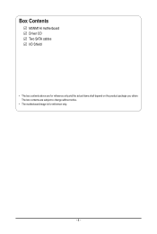
The box contents are for reference only. - 4 - Box Contents M5NM1AI motherboard Driver CD Two SATA cables I/O Shield • The box contents above are subject to change without notice. • The motherboard image is for reference only and the actual items shall depend on the product package you obtain.
The box contents are for reference only. - 4 - Box Contents M5NM1AI motherboard Driver CD Two SATA cables I/O Shield • The box contents above are subject to change without notice. • The motherboard image is for reference only and the actual items shall depend on the product package you obtain.
User Manual
Page 5
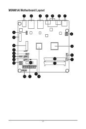
M5NM1AI Motherboard Layout 12 3 45 67 26 25 24 23 22 21 20 19 16 8 9 10 12 11 13 15 18 17 14 - 5 -
M5NM1AI Motherboard Layout 12 3 45 67 26 25 24 23 22 21 20 19 16 8 9 10 12 11 13 15 18 17 14 - 5 -
User Manual
Page 7
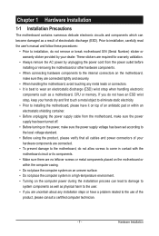
...Turning on the computer power during the installation process can become damaged as a motherboard, CPU or memory. If you are connected tightly and securely. • When handling the motherboard, avoid touching any installation steps or have it on top of an antistatic...handling electronic components such as a result of electrostatic discharge (ESD). Hardware Installation Chapter 1 Hardware Installation 1-1 Installation Precautions The motherboard contains numerous delicate electronic circuits and components which can lead to damage to system components as well as physical harm to the...
...Turning on the computer power during the installation process can become damaged as a motherboard, CPU or memory. If you are connected tightly and securely. • When handling the motherboard, avoid touching any installation steps or have it on top of an antistatic...handling electronic components such as a result of electrostatic discharge (ESD). Hardware Installation Chapter 1 Hardware Installation 1-1 Installation Precautions The motherboard contains numerous delicate electronic circuits and components which can lead to damage to system components as well as physical harm to the...
User Manual
Page 10
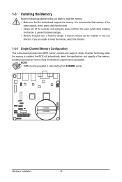
...from the power outlet before you are unable to insert the memory, switch the direction. 1-3-1 Single Channel Memory Configuration This motherboard provides two DDR3 memory sockets and supports Single Channel Technology. SODIMM1 SODIMM2 Hardware Installation - 10 - Enabling Dual Channel memory ... of the memory. NOTE! • DIMM must be populated in only one direction. After the memory is recommended that the motherboard supports the memory. 1-3 Installing the Memory Read the following guidelines before installing the memory to prevent hardware damage. • Memory modules...
...from the power outlet before you are unable to insert the memory, switch the direction. 1-3-1 Single Channel Memory Configuration This motherboard provides two DDR3 memory sockets and supports Single Channel Technology. SODIMM1 SODIMM2 Hardware Installation - 10 - Enabling Dual Channel memory ... of the memory. NOTE! • DIMM must be populated in only one direction. After the memory is recommended that the motherboard supports the memory. 1-3 Installing the Memory Read the following guidelines before installing the memory to prevent hardware damage. • Memory modules...
User Manual
Page 11
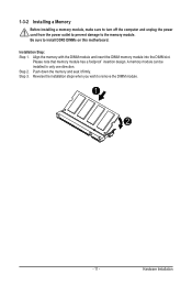
... DIMM module and insert the DIMM memory module into the DIMM slot. Reverse the installation steps when you wish to install DDR3 DIMMs on this motherboard. Be sure to remove the DIMM module. 1 2 - 11 - Push down the memory and seat it firmly. 1-3-2 Installing a Memory Before installing a memory module, make sure to...
... DIMM module and insert the DIMM memory module into the DIMM slot. Reverse the installation steps when you wish to install DDR3 DIMMs on this motherboard. Be sure to remove the DIMM module. 1 2 - 11 - Push down the memory and seat it firmly. 1-3-2 Installing a Memory Before installing a memory module, make sure to...
User Manual
Page 13
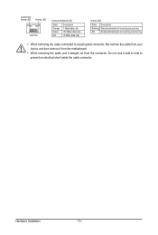
Do not rock it side to side to a back panel connector, first remove the cable from your device and then remove it from the motherboard. • When removing the cable, pull it straight out from the connector. Hardware Installation - 13 - Connection/ Speed LED Activity LED LAN Port Connection/Speed LED: ...
Do not rock it side to side to a back panel connector, first remove the cable from your device and then remove it from the motherboard. • When removing the cable, pull it straight out from the connector. Hardware Installation - 13 - Connection/ Speed LED Activity LED LAN Port Connection/Speed LED: ...
User Manual
Page 14
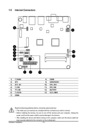
... devices and your devices are compliant with the connectors you wish to connect. • Before installing the devices, be sure to the connector on the motherboard. Hardware Installation - 14 - 1-5 Internal Connectors 6 3 5 4 7 10 9 11 8 12 12 1) F_PANEL 2) ATX 3) ATX_12V 4) F_USB 5) TP_USB 6) F_AUDIO 7) COMA 13 8) COMB 9) SATA0/SATA1 10) CPU_FAN 11) SYS_FAN 12...
... devices and your devices are compliant with the connectors you wish to connect. • Before installing the devices, be sure to the connector on the motherboard. Hardware Installation - 14 - 1-5 Internal Connectors 6 3 5 4 7 10 9 11 8 12 12 1) F_PANEL 2) ATX 3) ATX_12V 4) F_USB 5) TP_USB 6) F_AUDIO 7) COMA 13 8) COMB 9) SATA0/SATA1 10) CPU_FAN 11) SYS_FAN 12...
User Manual
Page 16
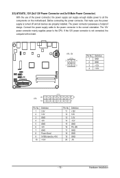
... power to the power connector in the correct orientation. Hardware Installation If the 12V power connector is turned off and all the components on the motherboard. Before connecting the power connector, first make sure the power supply is not connected, the computer will not start. The power connector possesses a foolproof design...
... power to the power connector in the correct orientation. Hardware Installation If the 12V power connector is turned off and all the components on the motherboard. Before connecting the power connector, first make sure the power supply is not connected, the computer will not start. The power connector possesses a foolproof design...
User Manual
Page 18
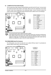
Incorrect connection between the module connector and the motherboard header will be present on each wire instead of the motherboard header. Make sure the wire assignments of the module connector match the pin assignments of a single plug. Definition 1 MIC2_L 2 GND 12 3 MIC2_R 4 FP_AUD_DET 5 LINE2_R 9 10 6 ...
Incorrect connection between the module connector and the motherboard header will be present on each wire instead of the motherboard header. Make sure the wire assignments of the module connector match the pin assignments of a single plug. Definition 1 MIC2_L 2 GND 12 3 MIC2_R 4 FP_AUD_DET 5 LINE2_R 9 10 6 ...
User Manual
Page 19
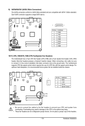
...a single SATA device. 7 1 Pin No. 1 2 3 4 5 6 7 Definition GND TXP TXN GND RXN RXP GND 10/11) CPU_FAN/SYS_FAN (CPU Fan/System Fan Headers) The motherboard has a 4-pin CPU fan header (CPU_FAN) and a 4-pin System fan header (SYS_FAN) header. Do not place a jumper cap on the headers. - 19 - The... motherboard supports CPU fan speed control, which requires the use of a CPU fan with SATA 1.5Gb/s standard. For optimum heat dissipation, it in damage to the...
...a single SATA device. 7 1 Pin No. 1 2 3 4 5 6 7 Definition GND TXP TXN GND RXN RXP GND 10/11) CPU_FAN/SYS_FAN (CPU Fan/System Fan Headers) The motherboard has a 4-pin CPU fan header (CPU_FAN) and a 4-pin System fan header (SYS_FAN) header. Do not place a jumper cap on the headers. - 19 - The... motherboard supports CPU fan speed control, which requires the use of a CPU fan with SATA 1.5Gb/s standard. For optimum heat dissipation, it in damage to the...
User Manual
Page 20
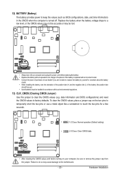
... up). • Used batteries must be handled in accordance with an equivalent one. date information and BIOS configurations) and reset the CMOS values to the motherboard. - 20 -
... up). • Used batteries must be handled in accordance with an equivalent one. date information and BIOS configurations) and reset the CMOS values to the motherboard. - 20 -
User Manual
Page 21
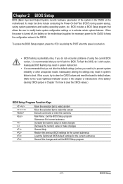
When the power is turned off, the battery on the motherboard supplies the necessary power to the CMOS to boot. To flash the BIOS, do not encounter problems of using the current BIOS version, it with ... the "Load Optimized Defaults" section in this chapter or introductions of the battery/ clearing CMOS jumper in system malfunction. • It is turned on the motherboard. BIOS Setup Its major functions include conducting the Power-On Self-Test (POST) during the POST when the power is recommended that you need to...
When the power is turned off, the battery on the motherboard supplies the necessary power to the CMOS to boot. To flash the BIOS, do not encounter problems of using the current BIOS version, it with ... the "Load Optimized Defaults" section in this chapter or introductions of the battery/ clearing CMOS jumper in system malfunction. • It is turned on the motherboard. BIOS Setup Its major functions include conducting the Power-On Self-Test (POST) during the POST when the power is recommended that you need to...


