User Manual
Page 1
M5NM1AI Intel® Atom™ D2550 processor motherboard User's Manual Rev. 1001
M5NM1AI Intel® Atom™ D2550 processor motherboard User's Manual Rev. 1001
User Manual
Page 3
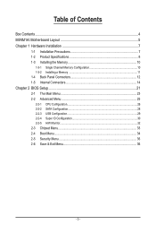
Table of Contents Box Contents...4 M5NM1AI Motherboard Layout 5 Chapter 1 Hardware Installation 7 1-1 Installation Precautions 7 1-2 Product Specifications 8 1-3 Installing the Memory 10 1-3-1 Single Channel Memory Configuration 10 1-3-2 Installing a Memory 11 1-4 Back Panel Connectors 12 1-5 Internal ...
Table of Contents Box Contents...4 M5NM1AI Motherboard Layout 5 Chapter 1 Hardware Installation 7 1-1 Installation Precautions 7 1-2 Product Specifications 8 1-3 Installing the Memory 10 1-3-1 Single Channel Memory Configuration 10 1-3-2 Installing a Memory 11 1-4 Back Panel Connectors 12 1-5 Internal ...
User Manual
Page 4
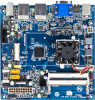
The box contents are for reference only. - 4 - Box Contents M5NM1AI motherboard Driver CD Two SATA cables I/O Shield • The box contents above are subject to change without notice. • The motherboard image is for reference only and the actual items shall depend on the product package you obtain.
The box contents are for reference only. - 4 - Box Contents M5NM1AI motherboard Driver CD Two SATA cables I/O Shield • The box contents above are subject to change without notice. • The motherboard image is for reference only and the actual items shall depend on the product package you obtain.
User Manual
Page 5
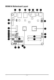
M5NM1AI Motherboard Layout 12 3 45 67 26 25 24 23 22 21 20 19 16 8 9 10 12 11 13 15 18 17 14 - 5 -
M5NM1AI Motherboard Layout 12 3 45 67 26 25 24 23 22 21 20 19 16 8 9 10 12 11 13 15 18 17 14 - 5 -
User Manual
Page 7
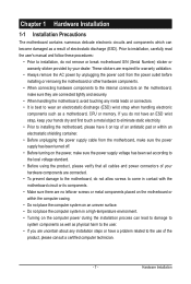
...system components as well as a result of the product, please consult a certified computer technician. - 7 - If you do not remove or break motherboard S/N (Serial Number) sticker or warranty sticker provided by your hands dry and first touch a metal object to eliminate static electricity. • Prior ... dealer. These stickers are required for warranty validation. • Always remove the AC power by unplugging the power cord from the motherboard, make sure the power supply has been turned off. • Before turning on the computer power during the installation process can become...
...system components as well as a result of the product, please consult a certified computer technician. - 7 - If you do not remove or break motherboard S/N (Serial Number) sticker or warranty sticker provided by your hands dry and first touch a metal object to eliminate static electricity. • Prior ... dealer. These stickers are required for warranty validation. • Always remove the AC power by unplugging the power cord from the motherboard, make sure the power supply has been turned off. • Before turning on the computer power during the installation process can become...
User Manual
Page 10
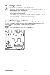
After the memory is recommended that the motherboard supports the memory. If you begin to install the memory: • Make sure that memory of the memory. NOTE! • DIMM must be used. • ... be installed in order starting from the power outlet before you are unable to insert the memory, switch the direction. 1-3-1 Single Channel Memory Configuration This motherboard provides two DDR3 memory sockets and supports Single Channel Technology. SODIMM1 SODIMM2 Hardware Installation - 10 -
After the memory is recommended that the motherboard supports the memory. If you begin to install the memory: • Make sure that memory of the memory. NOTE! • DIMM must be used. • ... be installed in order starting from the power outlet before you are unable to insert the memory, switch the direction. 1-3-1 Single Channel Memory Configuration This motherboard provides two DDR3 memory sockets and supports Single Channel Technology. SODIMM1 SODIMM2 Hardware Installation - 10 -
User Manual
Page 11
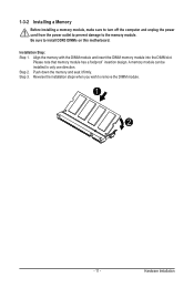
... module and insert the DIMM memory module into the DIMM slot. Step 3. Reverse the installation steps when you wish to install DDR3 DIMMs on this motherboard. Be sure to remove the DIMM module. 1 2 - 11 - Push down the memory and seat it firmly. 1-3-2 Installing a Memory Before installing a memory module, make sure to...
... module and insert the DIMM memory module into the DIMM slot. Step 3. Reverse the installation steps when you wish to install DDR3 DIMMs on this motherboard. Be sure to remove the DIMM module. 1 2 - 11 - Push down the memory and seat it firmly. 1-3-2 Installing a Memory Before installing a memory module, make sure to...
User Manual
Page 13
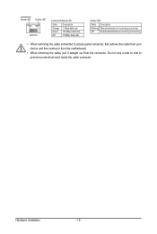
... - 13 - Do not rock it side to side to a back panel connector, first remove the cable from your device and then remove it from the motherboard. • When removing the cable, pull it straight out from the connector. Connection/ Speed LED Activity LED LAN Port Connection/Speed LED: State Orange Green...
... - 13 - Do not rock it side to side to a back panel connector, first remove the cable from your device and then remove it from the motherboard. • When removing the cable, pull it straight out from the connector. Connection/ Speed LED Activity LED LAN Port Connection/Speed LED: State Orange Green...
User Manual
Page 14
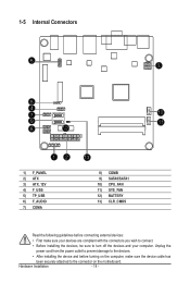
... devices and your devices are compliant with the connectors you wish to connect. • Before installing the devices, be sure to the connector on the motherboard. Hardware Installation - 14 - 1-5 Internal Connectors 6 3 5 4 7 10 9 11 8 12 12 1) F_PANEL 2) ATX 3) ATX_12V 4) F_USB 5) TP_USB 6) F_AUDIO 7) COMA 13 8) COMB 9) SATA0/SATA1 10) CPU_FAN 11) SYS_FAN 12...
... devices and your devices are compliant with the connectors you wish to connect. • Before installing the devices, be sure to the connector on the motherboard. Hardware Installation - 14 - 1-5 Internal Connectors 6 3 5 4 7 10 9 11 8 12 12 1) F_PANEL 2) ATX 3) ATX_12V 4) F_USB 5) TP_USB 6) F_AUDIO 7) COMA 13 8) COMB 9) SATA0/SATA1 10) CPU_FAN 11) SYS_FAN 12...
User Manual
Page 16
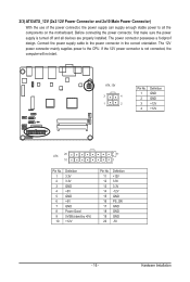
If the 12V power connector is turned off and all the components on the motherboard. ATX_12V FDD ATX_12V 3 4 1 2 Pin No. 1 2 3 4 Definition GND GND +12V +12V 20 ATX 10 11 1 Pin No. The 12V power connector mainly supplies power to the ...
If the 12V power connector is turned off and all the components on the motherboard. ATX_12V FDD ATX_12V 3 4 1 2 Pin No. 1 2 3 4 Definition GND GND +12V +12V 20 ATX 10 11 1 Pin No. The 12V power connector mainly supplies power to the ...
User Manual
Page 18
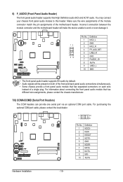
...3 4 5 6 7 8 9 10 Definition NDCDNSIN NSOUT NDTRGND NDSRNRTSNCTSNRINo Pin Hardware Installation - 18 - Incorrect connection between the module connector and the motherboard header will be present on both of the front and back panel audio connections simultaneously. • Some chassis provide a front panel audio module that has...AC'97 audio. For information about connecting the front panel audio module that has separated connectors on each wire instead of the motherboard header. Pin No. You may connect your chassis front panel audio module to work or even damage it. Definition 1 ...
...3 4 5 6 7 8 9 10 Definition NDCDNSIN NSOUT NDTRGND NDSRNRTSNCTSNRINo Pin Hardware Installation - 18 - Incorrect connection between the module connector and the motherboard header will be present on both of the front and back panel audio connections simultaneously. • Some chassis provide a front panel audio module that has...AC'97 audio. For information about connecting the front panel audio module that has separated connectors on each wire instead of the motherboard header. Pin No. You may connect your chassis front panel audio module to work or even damage it. Definition 1 ...
User Manual
Page 19
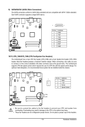
The motherboard supports CPU fan speed control, which requires the use of a CPU fan with SATA 1.5Gb/s standard. Hardware Installation Overheating may hang. • These fan headers ... connector supports a single SATA device. 7 1 Pin No. 1 2 3 4 5 6 7 Definition GND TXP TXN GND RXN RXP GND 10/11) CPU_FAN/SYS_FAN (CPU Fan/System Fan Headers) The motherboard has a 4-pin CPU fan header (CPU_FAN) and a 4-pin System fan header (SYS_FAN) header.
The motherboard supports CPU fan speed control, which requires the use of a CPU fan with SATA 1.5Gb/s standard. Hardware Installation Overheating may hang. • These fan headers ... connector supports a single SATA device. 7 1 Pin No. 1 2 3 4 5 6 7 Definition GND TXP TXN GND RXN RXP GND 10/11) CPU_FAN/SYS_FAN (CPU Fan/System Fan Headers) The motherboard has a 4-pin CPU fan header (CPU_FAN) and a 4-pin System fan header (SYS_FAN) header.
User Manual
Page 20
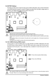
..., note the orientation of the positive side (+) and the negative side (-) of explosion if the battery is turned off your computer, be sure to the motherboard. - 20 - Failure to do so may be lost. • Always turn off . Replace the battery when the battery voltage drops to keep the values (such...
..., note the orientation of the positive side (+) and the negative side (-) of explosion if the battery is turned off your computer, be sure to the motherboard. - 20 - Failure to do so may be lost. • Always turn off . Replace the battery when the battery voltage drops to keep the values (such...
User Manual
Page 21
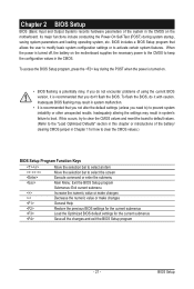
...unexpected results. Chapter 2 BIOS Setup BIOS (Basic Input and Output System) records hardware parameters of the system in the CMOS on the motherboard supplies the necessary power to the CMOS to keep the configuration values in the CMOS. Inadequate BIOS flashing may result in system's failure ...submenus Save all the changes and exit the BIOS Setup program - 21 - When the power is turned off, the battery on the motherboard. BIOS Setup Inadequately altering the settings may result in Chapter 1 for how to clear the CMOS values.) BIOS Setup Program Function Keys Move...
...unexpected results. Chapter 2 BIOS Setup BIOS (Basic Input and Output System) records hardware parameters of the system in the CMOS on the motherboard supplies the necessary power to the CMOS to keep the configuration values in the CMOS. Inadequate BIOS flashing may result in system's failure ...submenus Save all the changes and exit the BIOS Setup program - 21 - When the power is turned off, the battery on the motherboard. BIOS Setup Inadequately altering the settings may result in Chapter 1 for how to clear the CMOS values.) BIOS Setup Program Function Keys Move...


