
Manual
Page 1
... save changes and exit BIOS Setup. CMOS Setup Utility-Copyright (C) 1984-2011 Award Software Integrated Peripherals eXtreme Hard Drive (XHD) PCH SATA Control Mode OROM UI and Banner SATA Port0-3 Native Mode USB Controllers USB Legacy Function USB Storage Function Azalia Codec Onboard H/W 1394 Onboard H/W LAN } SMART LAN Onboard LAN Boot ROM R_USB30 Controller R_USB30 Turbo F_USB30 Controller GSATA3 Controller GSATA3 Ctrl Mode Onboard Serial Port 1 [Disabled] [RAID(XHD)] [Enabled] [Enabled] [Enabled] [Enabled] [Enabled] [Auto] [Enabled...
... save changes and exit BIOS Setup. CMOS Setup Utility-Copyright (C) 1984-2011 Award Software Integrated Peripherals eXtreme Hard Drive (XHD) PCH SATA Control Mode OROM UI and Banner SATA Port0-3 Native Mode USB Controllers USB Legacy Function USB Storage Function Azalia Codec Onboard H/W 1394 Onboard H/W LAN } SMART LAN Onboard LAN Boot ROM R_USB30 Controller R_USB30 Turbo F_USB30 Controller GSATA3 Controller GSATA3 Ctrl Mode Onboard Serial Port 1 [Disabled] [RAID(XHD)] [Enabled] [Enabled] [Enabled] [Enabled] [Enabled] [Auto] [Enabled...
Manual
Page 4
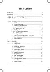
...Memory 16 1-4-1 Dual Channel Memory Configuration 16 1-4-2 Installing a Memory 17 1-5 Installing an Expansion Card 18 1-6 Setting up ATI CrossFireX™/NVIDIA SLI Configuration 19 1-7 Back Panel Connectors 20 1-8 Internal Connectors 22 Chapter 2 BIOS Setup 33 2-1 Startup Screen 34 2-2 The Main Menu 35 2-3 MB Intelligent Tweaker(M.I.T 37 2-4 Standard CMOS Features 45 2-5 Advanced BIOS Features 47 2-6 Integrated Peripherals 49 2-7 Power Management Setup 52 2-8 PC Health Status 54 2-9 Load Fail-Safe Defaults 56 2-10 Load Optimized Defaults 56 2-11 Set Supervisor/User Password...
...Memory 16 1-4-1 Dual Channel Memory Configuration 16 1-4-2 Installing a Memory 17 1-5 Installing an Expansion Card 18 1-6 Setting up ATI CrossFireX™/NVIDIA SLI Configuration 19 1-7 Back Panel Connectors 20 1-8 Internal Connectors 22 Chapter 2 BIOS Setup 33 2-1 Startup Screen 34 2-2 The Main Menu 35 2-3 MB Intelligent Tweaker(M.I.T 37 2-4 Standard CMOS Features 45 2-5 Advanced BIOS Features 47 2-6 Integrated Peripherals 49 2-7 Power Management Setup 52 2-8 PC Health Status 54 2-9 Load Fail-Safe Defaults 56 2-10 Load Optimized Defaults 56 2-11 Set Supervisor/User Password...
Manual
Page 19
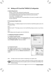
... cards. Step 3: Plug the display cable into the graphics card on your graphics cards for the power requirement) B. 1-6 Setting up ATI CrossFireX™/NVIDIA SLI Configuration A. System Requirements - Windows 7, Windows Vista or Windows XP operating system - A CrossFireX/SLI-supported motherboard with sufficient power is recommended (Refer to the CrossFireX menu and ensure the Enable CrossFireX™ check box is enabled. (Note) The bridge connector may differ by graphics cards. A power supply with two PCI Express x16 slots and correct driver - Connecting the Graphics...
... cards. Step 3: Plug the display cable into the graphics card on your graphics cards for the power requirement) B. 1-6 Setting up ATI CrossFireX™/NVIDIA SLI Configuration A. System Requirements - Windows 7, Windows Vista or Windows XP operating system - A CrossFireX/SLI-supported motherboard with sufficient power is recommended (Refer to the CrossFireX menu and ensure the Enable CrossFireX™ check box is enabled. (Note) The bridge connector may differ by graphics cards. A power supply with two PCI Express x16 slots and correct driver - Connecting the Graphics...
Manual
Page 34
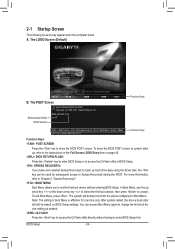
...In Boot Menu, use the up hard drive data using the driver disk, the key can access Boot Menu again to change the first boot device setting as needed. : Q-FLASH Press the key to access the Q-Flash utility directly without having to set the first boot device without entering BIOS Setup. After system restart, the device boot order will directly boot from the device configured in Boot Menu. Motherboard Model BIOS Version Z68X-UD4-B3 F2a . . . . : BIOS Setup : XpressRecovery2 : Boot Menu : Qflash 03/21/2011-Z68-7A89VG0TC-00 Function Keys Function Keys Function Keys: : POST SCREEN Press...
...In Boot Menu, use the up hard drive data using the driver disk, the key can access Boot Menu again to change the first boot device setting as needed. : Q-FLASH Press the key to access the Q-Flash utility directly without having to set the first boot device without entering BIOS Setup. After system restart, the device boot order will directly boot from the device configured in Boot Menu. Motherboard Model BIOS Version Z68X-UD4-B3 F2a . . . . : BIOS Setup : XpressRecovery2 : Boot Menu : Qflash 03/21/2011-Z68-7A89VG0TC-00 Function Keys Function Keys Function Keys: : POST SCREEN Press...
Manual
Page 39
... frequency in system halt state. PWM Frequency Control Allows you install a CPU that support multi-processor mode. (Default: Enabled) CPU Enhanced Halt (C1E) (Note) Enables or disables Intel CPU Enhanced Halt (C1E) function, a CPU power-saving function in order to set the maximum over-current value for CPU Turbo mode. Auto sets the power limit according to the CPU specifications. (Default: Auto) Core Current Limit (Amps) Allows you to reduce the power. Auto lets the BIOS automatically configure this setting. (Default: Auto) Turbo Ratio (1-Core)/(2-Core)/(3-Core)/(4-Core...
... frequency in system halt state. PWM Frequency Control Allows you install a CPU that support multi-processor mode. (Default: Enabled) CPU Enhanced Halt (C1E) (Note) Enables or disables Intel CPU Enhanced Halt (C1E) function, a CPU power-saving function in order to set the maximum over-current value for CPU Turbo mode. Auto sets the power limit according to the CPU specifications. (Default: Auto) Core Current Limit (Amps) Allows you to reduce the power. Auto lets the BIOS automatically configure this setting. (Default: Auto) Turbo Ratio (1-Core)/(2-Core)/(3-Core)/(4-Core...
Manual
Page 40
... XMP memory module(s) to enhance memory performance when enabled. For more enhanced power-saving state than C1. Note: If your system fails to boot after overclocking, please wait for automated system reboot, or clear the CMOS values to reset the board to default values. (Default: Disabled) BCLK/DMI/PEG Frequency(0.1MHz) Allows you to 2000 MHz. Disabled Disables this setting. (Default: Auto) CPU Thermal Monitor (Note 1) Enables or disables Intel CPU Thermal Monitor function, a CPU overheating...
... XMP memory module(s) to enhance memory performance when enabled. For more enhanced power-saving state than C1. Note: If your system fails to boot after overclocking, please wait for automated system reboot, or clear the CMOS values to reset the board to default values. (Default: Disabled) BCLK/DMI/PEG Frequency(0.1MHz) Allows you to 2000 MHz. Disabled Disables this setting. (Default: Auto) CPU Thermal Monitor (Note 1) Enables or disables Intel CPU Thermal Monitor function, a CPU overheating...
Manual
Page 43
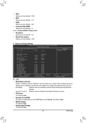
...Trip Latency Options are: Auto (default), 1~255. Advanced Voltage Settings CMOS Setup Utility-Copyright (C) 1984-2011 Award Software Advanced Voltage Settings ****** Mother Board Voltage Control ****** Voltage Types Normal Current >>> CPU Multi-Steps Load-Line [Disabled] CPU Vcore 1.220V [Auto] x Dynamic Vcore(DVID) +0.000V Auto QPI/Vtt Voltage 1.050V [Auto] System Agent Voltage 0.920V [Auto] >>> MCH/ICH CPU PLL 1.800V [Auto] >>> DRAM DRAM Voltage 1.500V [Auto] DRAM VRef. 0.750V [Auto] DRAM Termination 0.750V [Auto] Ch...
...Trip Latency Options are: Auto (default), 1~255. Advanced Voltage Settings CMOS Setup Utility-Copyright (C) 1984-2011 Award Software Advanced Voltage Settings ****** Mother Board Voltage Control ****** Voltage Types Normal Current >>> CPU Multi-Steps Load-Line [Disabled] CPU Vcore 1.220V [Auto] x Dynamic Vcore(DVID) +0.000V Auto QPI/Vtt Voltage 1.050V [Auto] System Agent Voltage 0.920V [Auto] >>> MCH/ICH CPU PLL 1.800V [Auto] >>> DRAM DRAM Voltage 1.500V [Auto] DRAM VRef. 0.750V [Auto] DRAM Termination 0.750V [Auto] Ch...
Manual
Page 44
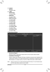
... Auto. DRAM VRef. DRAM Termination The default is present only if you install a CPU that supports this feature. The default is Auto. The default is Auto. Ch-A Address VRef. >>> MCH/ICH CPU PLL The default is Auto. >>> DRAM DRAM Voltage The default is Auto. Miscellaneous Settings CMOS Setup Utility-Copyright (C) 1984-2011 Award Software Miscellaneous Settings Isochronous Support Virtualization Technology (Note) [Enabled] [Enabled] Item Help Menu Level Move Enter: Select F5: Previous Values +/-/PU/PD: Value F10: Save F6: Fail-Safe Defaults...
... Auto. DRAM VRef. DRAM Termination The default is present only if you install a CPU that supports this feature. The default is Auto. The default is Auto. Ch-A Address VRef. >>> MCH/ICH CPU PLL The default is Auto. >>> DRAM DRAM Voltage The default is Auto. Miscellaneous Settings CMOS Setup Utility-Copyright (C) 1984-2011 Award Software Miscellaneous Settings Isochronous Support Virtualization Technology (Note) [Enabled] [Enabled] Item Help Menu Level Move Enter: Select F5: Previous Values +/-/PU/PD: Value F10: Save F6: Fail-Safe Defaults...
Manual
Page 47
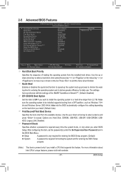
... key (or ) to 3 (Note) No-Execute Memory Protect (Note) Delay For HDD (Secs) Full Screen LOGO Show Init Display First [Press Enter] [Disabled] [Auto] [Hard Disk] [CDROM] [USB-FDD] [Setup] [Disabled] [Disabled] [Enabled] [0] [Enabled] [PCI] Item Help Menu Level Move Enter: Select F5: Previous Values +/-/PU/PD: Value F10: Save F6: Fail-Safe Defaults ESC: Exit F1: General Help F7: Optimized Defaults Hard Disk Boot Priority Specifies the sequence of Smart 6™. (Default: Disabled) EFI CD/DVD Boot Option Set this menu...
... key (or ) to 3 (Note) No-Execute Memory Protect (Note) Delay For HDD (Secs) Full Screen LOGO Show Init Display First [Press Enter] [Disabled] [Auto] [Hard Disk] [CDROM] [USB-FDD] [Setup] [Disabled] [Disabled] [Enabled] [0] [Enabled] [PCI] Item Help Menu Level Move Enter: Select F5: Previous Values +/-/PU/PD: Value F10: Save F6: Fail-Safe Defaults ESC: Exit F1: General Help F7: Optimized Defaults Hard Disk Boot Priority Specifies the sequence of Smart 6™. (Default: Disabled) EFI CD/DVD Boot Option Set this menu...

Manual
Page 48
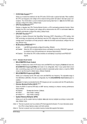
... system; PCI Sets the PCI graphics card as the first display. (Default) PCIE x16 Sets the PCI Express graphics card on the PCIEX8 slot as Windows NT4.0. (Default: Disabled) No-Execute Memory Protect (Note) Enables or disables Intel Execute Disable Bit function. PCIE x8 Sets the PCI Express graphics card on the PCIEX16 slot as the system boots up. to 3 (Note) Allows you install a CPU that supports this item to Disabled for the BIOS to issue warnings when a third party hardware monitor utility is installed. (Default: Disabled) Limit CPUID Max. HDD S.M.A.R.T. The...
... system; PCI Sets the PCI graphics card as the first display. (Default) PCIE x16 Sets the PCI Express graphics card on the PCIEX8 slot as Windows NT4.0. (Default: Disabled) No-Execute Memory Protect (Note) Enables or disables Intel Execute Disable Bit function. PCIE x8 Sets the PCI Express graphics card on the PCIEX16 slot as the system boots up. to 3 (Note) Allows you install a CPU that supports this item to Disabled for the BIOS to issue warnings when a third party hardware monitor utility is installed. (Default: Disabled) Limit CPUID Max. HDD S.M.A.R.T. The...
Manual
Page 50
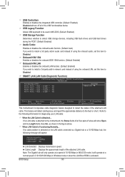
... Windows mode or when the LAN Boot ROM is attached to Disabled. Note: The Gigabit hub will only operate at Port..... it will operate at Port..... BIOS Setup - 50 - USB Controllers Enables or disables the integrated USB controller. (Default: Enabled) Disabled will turn off all four pairs of wires will show Open and the Length fields show 0m, as shown in the figure above. USB Legacy Function Allows USB keyboard to be used in MS-DOS. (Default: Enabled) USB Storage...
... Windows mode or when the LAN Boot ROM is attached to Disabled. Note: The Gigabit hub will only operate at Port..... it will operate at Port..... BIOS Setup - 50 - USB Controllers Enables or disables the integrated USB controller. (Default: Enabled) Disabled will turn off all four pairs of wires will show Open and the Length fields show 0m, as shown in the figure above. USB Legacy Function Allows USB keyboard to be used in MS-DOS. (Default: Enabled) USB Storage...
Manual
Page 51
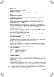
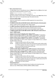
...hot plug. RAID Enables RAID for the SATA controllers. RAID Enables RAID for the SATA controllers. If a cable problem occurs on the back panel) Enables or disables the Turbo USB mode for the Etron EJ168 USB controller. Advanced Host Controller Interface (AHCI) is an interface specification that allows the storage driver to activate the boot ROM integrated with the onboard LAN chip. (Default: Disabled) R_USB30 Controller (Etron EJ168 USB Controller, USB 3.0/2.0 ports on the back panel) Enables or disables the Etron EJ168 USB controller. (Default: Enabled) R_USB30...
...hot plug. RAID Enables RAID for the SATA controllers. RAID Enables RAID for the SATA controllers. If a cable problem occurs on the back panel) Enables or disables the Turbo USB mode for the Etron EJ168 USB controller. Advanced Host Controller Interface (AHCI) is an interface specification that allows the storage driver to activate the boot ROM integrated with the onboard LAN chip. (Default: Disabled) R_USB30 Controller (Etron EJ168 USB Controller, USB 3.0/2.0 ports on the back panel) Enables or disables the Etron EJ168 USB controller. (Default: Enabled) R_USB30...
Manual
Page 67
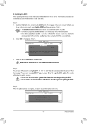
Make sure the BIOS update file matches your motherboard model. Step 3: When the update process is updating the BIOS. Q-Flash Utility v2.23 Flash Type/Size MXIC 25L3206E 4M Keep DMI Data Enable !L! Unique Features Q-Flash Utility v2.23 Flash Type/Size MXIC 25L3206E 4M Keep0 DfilMe(Is)DfaotuandEnable HDD 1-0 Loa d CMO S Default Enable Update BIOS from the USB flash drive is displayed on the screen. Step 2: The process of Q-Flash, use the key during the POST to the main menu. The monitor will display the update process. • Do...
Make sure the BIOS update file matches your motherboard model. Step 3: When the update process is updating the BIOS. Q-Flash Utility v2.23 Flash Type/Size MXIC 25L3206E 4M Keep DMI Data Enable !L! Unique Features Q-Flash Utility v2.23 Flash Type/Size MXIC 25L3206E 4M Keep0 DfilMe(Is)DfaotuandEnable HDD 1-0 Loa d CMO S Default Enable Update BIOS from the USB flash drive is displayed on the screen. Step 2: The process of Q-Flash, use the key during the POST to the main menu. The monitor will display the update process. • Do...
Manual
Page 79
... and configure it for RAID 0. B. To manually set up a RAID array: (Note 3) Click Manual to automatically and quickly set up a RAID 0 array: Click Auto to access the Intel Rapid Storage Technology, with a simple click of data. (Note 3) If you manually build a non-RAID 0 array, you'll not be recognized during the Windows setup process. (For more details, refer to Chapter 5, "Installing the SATA RAID/AHCI Driver and Operating System." ) Step 3: Install the motherboard drivers...
... and configure it for RAID 0. B. To manually set up a RAID array: (Note 3) Click Manual to automatically and quickly set up a RAID 0 array: Click Auto to access the Intel Rapid Storage Technology, with a simple click of data. (Note 3) If you manually build a non-RAID 0 array, you'll not be recognized during the Windows setup process. (For more details, refer to Chapter 5, "Installing the SATA RAID/AHCI Driver and Operating System." ) Step 3: Install the motherboard drivers...
Manual
Page 81
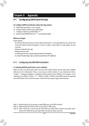
... the SATA controller for the SATA port. (For example, on the devices being connected. - 81 - Configure SATA controller mode in RAID BIOS. (Note 1) D. Before you may vary depending on this motherboard, the SATA3_0, SATA3_1 (Note 3), SATA2_2, SATA2_3, SATA2_4 and SATA2_5 ports are supported by the Z68 Chipset.) Then connect the power connector from your computer. Install the SATA RAID/AHCI driver (Note 2) and operating system. Chapter 5 Appendix 5-1 Configuring SATA Hard Drive(s) To configure SATA hard drive(s), follow the steps below: A. Configure a RAID array in BIOS Setup.
... the SATA controller for the SATA port. (For example, on the devices being connected. - 81 - Configure SATA controller mode in RAID BIOS. (Note 1) D. Before you may vary depending on this motherboard, the SATA3_0, SATA3_1 (Note 3), SATA2_2, SATA2_3, SATA2_4 and SATA2_5 ports are supported by the Z68 Chipset.) Then connect the power connector from your computer. Install the SATA RAID/AHCI driver (Note 2) and operating system. Chapter 5 Appendix 5-1 Configuring SATA Hard Drive(s) To configure SATA hard drive(s), follow the steps below: A. Configure a RAID array in BIOS Setup.
Manual
Page 89
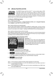
... Set eSATA3 Controller to Enabled Set eSATA3 Ctrl Mode to Integrated Peripherals. In BIOS Setup, go to RAID CMOS Setup Utility-Copyright (C) 1984-2011 Award Software Integrated Peripherals eXtreme Hard Drive (XHD) PCH SATA Control Mode SATA Port0-3 Native Mode USB Controllers USB Legacy Function USB Storage Function Azalia Codec Onboard H/W 1394 Onboard H/W LAN } SMART LAN Onboard LAN Boot ROM R_USB30 Controller R_USB30 Turbo F_USB30 Controller GSATA3 Controller GSATA3 Ctrl Mode eSATA3 Controller eSATA3 Ctrl Mode Onboard Serial Port...
... Set eSATA3 Controller to Enabled Set eSATA3 Ctrl Mode to Integrated Peripherals. In BIOS Setup, go to RAID CMOS Setup Utility-Copyright (C) 1984-2011 Award Software Integrated Peripherals eXtreme Hard Drive (XHD) PCH SATA Control Mode SATA Port0-3 Native Mode USB Controllers USB Legacy Function USB Storage Function Azalia Codec Onboard H/W 1394 Onboard H/W LAN } SMART LAN Onboard LAN Boot ROM R_USB30 Controller R_USB30 Turbo F_USB30 Controller GSATA3 Controller GSATA3 Ctrl Mode eSATA3 Controller eSATA3 Ctrl Mode Onboard Serial Port...
Manual
Page 95
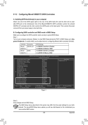
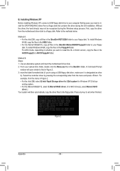
... Windows installation process. After the operating system is installed, we recommend that you install all required drivers from the Windows 7/Vista setup disk and perform standard OS installation steps. The locations of the driver. For the Marvell 88SE9172: Step 1: Boot from the motherboard driver disk using "Xpress Install" to install Windows?" Appendix A. 5-1-3 Installing the SATA RAID/AHCI Driver and Operating System With the correct BIOS settings, you are as follows: RAID driver for Windows 32-bit: \BootDrv\Marvell\RAID\i386 RAID driver for Windows...
... Windows installation process. After the operating system is installed, we recommend that you install all required drivers from the Windows 7/Vista setup disk and perform standard OS installation steps. The locations of the driver. For the Marvell 88SE9172: Step 1: Boot from the motherboard driver disk using "Xpress Install" to install Windows?" Appendix A. 5-1-3 Installing the SATA RAID/AHCI Driver and Operating System With the correct BIOS settings, you are as follows: RAID driver for Windows 32-bit: \BootDrv\Marvell\RAID\i386 RAID driver for Windows...
Manual
Page 96
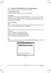
... Windows XP 32-bit op- To install Windows 64-Bit, copy the files in the \BootDrv\Marvell\RAID\Floppy32 folder to the floppy disk. For example, from a floppy disk that in Figure 2. 3: nsert the blank formatted disk (if you're using a USB floppy disk drive, make sure it is designated as drive A). Press any key to the methods below. For AHCI mode, depending on whether you need to install the SATA RAID/AHCI driver from the menu...
... Windows XP 32-bit op- To install Windows 64-Bit, copy the files in the \BootDrv\Marvell\RAID\Floppy32 folder to the floppy disk. For example, from a floppy disk that in Figure 2. 3: nsert the blank formatted disk (if you're using a USB floppy disk drive, make sure it is designated as drive A). Press any key to the methods below. For AHCI mode, depending on whether you need to install the SATA RAID/AHCI driver from the menu...
Manual
Page 98
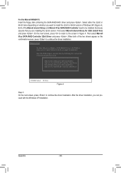
... 91xx SATA RAID Controller need to the previous screen. Select the SCSI Adapter you are installing the 32-bit version. Appendix - 98 - Below we assume that you want to install the 32-bit or 64-bit version of the two drivers appear on whether you can proceed with Windows, using a device support disk provided by an adapter manufacturer. For the Marvell 88SE9172: Insert the floppy disk containing the SATA RAID/AHCI driver and...
... 91xx SATA RAID Controller need to the previous screen. Select the SCSI Adapter you are installing the 32-bit version. Appendix - 98 - Below we assume that you want to install the 32-bit or 64-bit version of the two drivers appear on whether you can proceed with Windows, using a device support disk provided by an adapter manufacturer. For the Marvell 88SE9172: Insert the floppy disk containing the SATA RAID/AHCI driver and...
Manual
Page 111
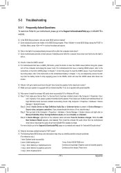
... go back to install. A: The following Award BIOS beep code descriptions may help you identify possible computer problems. (For reference only.) 1 short: System boots successfully 2 short: CMOS setting error 1 long, 9 short: BIOS ROM error 1 long, 1 short: Memory or motherboard error Continuous long beeps: Graphics card not inserted properly 1 long, 2 short: Monitor or graphics card error Continuous short beeps: Power error 1 long, 3 short: Keyboard error - 111 - Q: Why is still on. If yes, please disable this device. (If not, skip this , please turn off the computer and...
... go back to install. A: The following Award BIOS beep code descriptions may help you identify possible computer problems. (For reference only.) 1 short: System boots successfully 2 short: CMOS setting error 1 long, 9 short: BIOS ROM error 1 long, 1 short: Memory or motherboard error Continuous long beeps: Graphics card not inserted properly 1 long, 2 short: Monitor or graphics card error Continuous short beeps: Power error 1 long, 3 short: Keyboard error - 111 - Q: Why is still on. If yes, please disable this device. (If not, skip this , please turn off the computer and...


