Manual
Page 3
..., read the Quick Installation Guide included with the product. For detailed product information, carefully read the User's Manual. Example: Copyright © 2011 GIGA-BYTE TECHNOLOGY CO., LTD. Check your motherboard looks like this product, GIGABYTE provides the following types of documentations: For quick set-up of this : "REV: X.X." All rights reserved...
..., read the Quick Installation Guide included with the product. For detailed product information, carefully read the User's Manual. Example: Copyright © 2011 GIGA-BYTE TECHNOLOGY CO., LTD. Check your motherboard looks like this product, GIGABYTE provides the following types of documentations: For quick set-up of this : "REV: X.X." All rights reserved...
Manual
Page 6
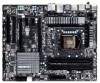
...cable (Part No. 12CF1-1CM001-3*R) 3.5" Front Panel with 2 USB 3.0/2.0 ports (Part No. 12CR1-FPX582-0*R) - 6 - Box Contents GA-Z68X-UD4-B3 motherboard Motherboard driver disk User's Manual Quick Installation Guide Four SATA cables I/O Shield One 2-Way SLI bridge connector • The box contents above are subject to change without ...notice. • The motherboard image is for reference only and the actual items shall depend on...
...cable (Part No. 12CF1-1CM001-3*R) 3.5" Front Panel with 2 USB 3.0/2.0 ports (Part No. 12CR1-FPX582-0*R) - 6 - Box Contents GA-Z68X-UD4-B3 motherboard Motherboard driver disk User's Manual Quick Installation Guide Four SATA cables I/O Shield One 2-Way SLI bridge connector • The box contents above are subject to change without ...notice. • The motherboard image is for reference only and the actual items shall depend on...
Manual
Page 9
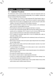
... remove the AC power by your dealer. Prior to installation, carefully read the user's manual and follow these procedures: •• Prior to installation, do not remove or break motherboard S/N (Serial Number) sticker or warranty sticker provided by unplugging the power cord from the... electrostatic shielding container. •• Before unplugging the power supply cable from the power outlet before installing or removing the motherboard or other hardware components. •• When connecting hardware components to the internal connectors on the computer power during the ...
... remove the AC power by your dealer. Prior to installation, carefully read the user's manual and follow these procedures: •• Prior to installation, do not remove or break motherboard S/N (Serial Number) sticker or warranty sticker provided by unplugging the power cord from the... electrostatic shielding container. •• Before unplugging the power supply cable from the power outlet before installing or removing the motherboard or other hardware components. •• When connecting hardware components to the internal connectors on the computer power during the ...
Manual
Page 15
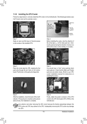
.... (Turning the push pin along the direction of arrow is to remove the cooler, on the contrary, is to your CPU cooler installation manual for instructions on installing the cooler.) Step 5: After the installation, check the back of the installed CPU. Push down each push pin. ...connector of thermal grease on the push pins diagonally. 1-3-2 Installing the CPU Cooler Follow the steps below to correctly install the CPU cooler on the motherboard. (The following procedure uses Intel® boxed cooler as the picture above shows, the installation is complete. Step 4: You should hear a "click...
.... (Turning the push pin along the direction of arrow is to remove the cooler, on the contrary, is to your CPU cooler installation manual for instructions on installing the cooler.) Step 5: After the installation, check the back of the installed CPU. Push down each push pin. ...connector of thermal grease on the push pins diagonally. 1-3-2 Installing the CPU Cooler Follow the steps below to correctly install the CPU cooler on the motherboard. (The following procedure uses Intel® boxed cooler as the picture above shows, the installation is complete. Step 4: You should hear a "click...
Manual
Page 18
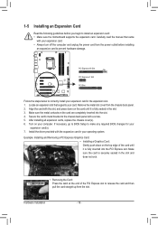
Remove the metal slot cover from the chassis back panel. 222 Align the card with your card. Carefully read the manual that supports your expansion card. • Always turn off the computer and unplug the power cord from the slot. 1-5 Installing an Expansion Card Read the ... operating system. PCI Express x16 Slot PCI Express x1 Slot PCI Slot Follow the steps below to install an expansion card: • Make sure the motherboard supports the expansion card.
Remove the metal slot cover from the chassis back panel. 222 Align the card with your card. Carefully read the manual that supports your expansion card. • Always turn off the computer and unplug the power cord from the slot. 1-5 Installing an Expansion Card Read the ... operating system. PCI Express x16 Slot PCI Express x1 Slot PCI Slot Follow the steps below to install an expansion card: • Make sure the motherboard supports the expansion card.
Manual
Page 19
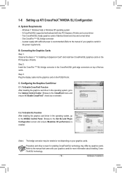
... After installing the graphics card driver in "1-5 Installing an Expansion Card" and install two CrossFireX/SLI graphics cards on the PCIEX16 slot. Refer to the manual of your graphics cards for more information about enabling CrossFireX/SLI technology. - 19 - Windows 7, Windows Vista or Windows XP operating system - C. C-2. Browse to the... After installing the graphics card driver in the CrossFireX/SLI gold edge connectors on your graphics cards for the power requirement) B. A CrossFireX/SLI-supported motherboard with your graphics cards. System Requirements -
... After installing the graphics card driver in "1-5 Installing an Expansion Card" and install two CrossFireX/SLI graphics cards on the PCIEX16 slot. Refer to the manual of your graphics cards for more information about enabling CrossFireX/SLI technology. - 19 - Windows 7, Windows Vista or Windows XP operating system - C. C-2. Browse to the... After installing the graphics card driver in the CrossFireX/SLI gold edge connectors on your graphics cards for the power requirement) B. A CrossFireX/SLI-supported motherboard with your graphics cards. System Requirements -

Manual
Page 28
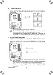
...Chapter 5, "Configuring 2/4/5.1/7.1-Channel Audio." •• Audio signals will make the device unable to this header. Incorrect connection between the module connector and the motherboard header will be present on both of the front and back panel audio connections simultaneously. Definition 9 1 1 MIC2_L 2 GND 1 MIC 2 GND 3 ...display at the same time. For information about connecting the S/PDIF digital audio cable, carefully read the manual for digital audio output from your motherboard to your graphics card if you wish to connect an HDMI display to the graphics card and have ...
...Chapter 5, "Configuring 2/4/5.1/7.1-Channel Audio." •• Audio signals will make the device unable to this header. Incorrect connection between the module connector and the motherboard header will be present on both of the front and back panel audio connections simultaneously. Definition 9 1 1 MIC2_L 2 GND 1 MIC 2 GND 3 ...display at the same time. For information about connecting the S/PDIF digital audio cable, carefully read the manual for digital audio output from your motherboard to your graphics card if you wish to connect an HDMI display to the graphics card and have ...
Manual
Page 30
... CMOS values to clear the CMOS values (e.g. Failure to do so may cause damage to the motherboard. •• After system restart, go to BIOS Setup to load factory defaults (select Load Optimized Defaults) or manually configure the BIOS settings (refer to IEEE 1394a specification. Definition 1 TPA+ 2 TPA- 9 1 10 2 3 GND- 4 GND 5 TPB...
... CMOS values to clear the CMOS values (e.g. Failure to do so may cause damage to the motherboard. •• After system restart, go to BIOS Setup to load factory defaults (select Load Optimized Defaults) or manually configure the BIOS settings (refer to IEEE 1394a specification. Definition 1 TPA+ 2 TPA- 9 1 10 2 3 GND- 4 GND 5 TPB...
Manual
Page 59
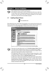
... install. • Please ignore the popup dialog box(es) (e.g. Or click Install Single Items to manually select the drivers you want to manually select the utilities to install. the Found New Hardware Wizard) displayed when "Xpress Install" is automatically ...restart, "Xpress Install" will continue to install new GIGABYTE utilities. Chapter 3 Drivers Installation • Before installing the drivers, first install the operating system. • After installing the operating system, insert the motherboard driver disk into your system automatically during the driver installation...
... install. • Please ignore the popup dialog box(es) (e.g. Or click Install Single Items to manually select the drivers you want to manually select the utilities to install. the Found New Hardware Wizard) displayed when "Xpress Install" is automatically ...restart, "Xpress Install" will continue to install new GIGABYTE utilities. Chapter 3 Drivers Installation • Before installing the drivers, first install the operating system. • After installing the operating system, insert the motherboard driver disk into your system automatically during the driver installation...
Manual
Page 60
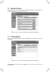
Drivers Installation - 60 - 3-2 Application Software This page displays all the utilities and applications that GIGABYTE develops and some free software. You can click the Install button on the right of an item to install it. 3-3 Technical Manuals This page provides GIGABYTE's application guides, content descriptions for this driver disk, and the motherboard manuals.
Drivers Installation - 60 - 3-2 Application Software This page displays all the utilities and applications that GIGABYTE develops and some free software. You can click the Install button on the right of an item to install it. 3-3 Technical Manuals This page provides GIGABYTE's application guides, content descriptions for this driver disk, and the motherboard manuals.
Manual
Page 66
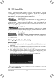
...is potentially risky, please do it with the Q-Flash Utility A. For the sake of going through complicated BIOS flashing process. Restart the system. Z68X-UD4-B3 F2a . . . . : BIOS Setup : XpressRecovery2 : Boot Menu : Qflash 03/21/2011-Z68-7A89VG0TC-00 Because BIOS flashing is saved...system safety, users cannot update the backup BIOS manually. Award Modular BIOS v6.00PG Copyright (C) 1984-2011, Award Software, Inc. 4-2 BIOS Update Utilities GIGABYTE motherboards provide two unique BIOS update tools, Q-Flash™ and @BIOS™. GIGABYTE Q-Flash and @BIOS are easy-to-use...
...is potentially risky, please do it with the Q-Flash Utility A. For the sake of going through complicated BIOS flashing process. Restart the system. Z68X-UD4-B3 F2a . . . . : BIOS Setup : XpressRecovery2 : Boot Menu : Qflash 03/21/2011-Z68-7A89VG0TC-00 Because BIOS flashing is saved...system safety, users cannot update the backup BIOS manually. Award Modular BIOS v6.00PG Copyright (C) 1984-2011, Award Software, Inc. 4-2 BIOS Update Utilities GIGABYTE motherboards provide two unique BIOS update tools, Q-Flash™ and @BIOS™. GIGABYTE Q-Flash and @BIOS are easy-to-use...
Manual
Page 69
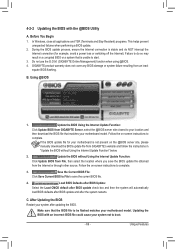
...applications and TSR (Terminate and Stay Resident) programs. This helps prevent unexpected failures when performing a BIOS update. 2. Do not use the G.O.M. (GIGABYTE Online Management) function when using @BIOS. 4. Follow the on -screen instructions to complete. 3. Follow the on -screen instructions to save the...the @BIOS Utility A. Before You Begin 1. Failure to do NOT interrupt the Internet connection (for your motherboard is not present on the @BIOS server site, please manually download the BIOS update file from File, then select the location where you save the current BIOS file....
...applications and TSR (Terminate and Stay Resident) programs. This helps prevent unexpected failures when performing a BIOS update. 2. Do not use the G.O.M. (GIGABYTE Online Management) function when using @BIOS. 4. Follow the on -screen instructions to complete. 3. Follow the on -screen instructions to save the...the @BIOS Utility A. Before You Begin 1. Failure to do NOT interrupt the Internet connection (for your motherboard is not present on the @BIOS server site, please manually download the BIOS update file from File, then select the location where you save the current BIOS file....
Manual
Page 79
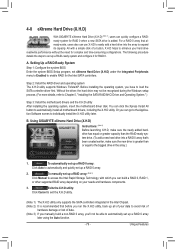
...easily add a hard drive into the array to enhance your hard drive read/write performance without the need for RAID 0. To manually set up all motherboard drivers, including the X.H.D utility. Or you can build a RAID 0, RAID 1, or other supported RAID array depending on your...be recognized during the Windows setup process. (For more details, refer to load the SATA controller driver first. 4-8 eXtreme Hard Drive (X.H.D) With GIGABYTE eXtreme Hard Drive (X.H.D) (Note 1), users can quickly configure a RAIDready system for the Intel SATA controllers. Step 2: Install the RAID driver ...
...easily add a hard drive into the array to enhance your hard drive read/write performance without the need for RAID 0. To manually set up all motherboard drivers, including the X.H.D utility. Or you can build a RAID 0, RAID 1, or other supported RAID array depending on your...be recognized during the Windows setup process. (For more details, refer to load the SATA controller driver first. 4-8 eXtreme Hard Drive (X.H.D) With GIGABYTE eXtreme Hard Drive (X.H.D) (Note 1), users can quickly configure a RAIDready system for the Intel SATA controllers. Step 2: Install the RAID driver ...
Manual
Page 103
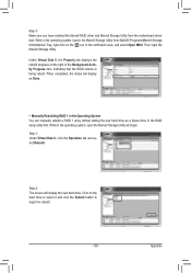
..., right-click on the icon in the notification area, and select Open MSU. Step 2: The screen will display as Done. • Manually Rebuilding RAID 1 in the Operating System You can manually rebuild a RAID 1 array without setting the new hard drive as a Spare drive in the operating system, open the Marvell Storage Utility... the Background Activity Progress item, indicating that the RAID volume is being rebuilt. While in the operating system, launch the Marvell Storage Utility from the motherboard driver disk.
..., right-click on the icon in the notification area, and select Open MSU. Step 2: The screen will display as Done. • Manually Rebuilding RAID 1 in the Operating System You can manually rebuild a RAID 1 array without setting the new hard drive as a Spare drive in the operating system, open the Marvell Storage Utility... the Background Activity Progress item, indicating that the RAID volume is being rebuilt. While in the operating system, launch the Marvell Storage Utility from the motherboard driver disk.
Manual
Page 104
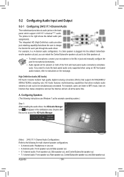
..., have an Internet chat, make a telephone call over the Internet, and etc. If you can listen to the Mic in jack and manually configure the jack for multi-channel speaker configurations. • 2-channel audio: Headphone or Line out. • 4-channel audio: Front speaker ...be present on both of the front and back panel audio connections simultaneously. 5-2 Configuring Audio Input and Output 5-2-1 Configuring 2/4/5.1/7.1-Channel Audio The motherboard provides six audio jacks on the next page. For example, in and out) to the following instructions use Windows 7 as the example ...
..., have an Internet chat, make a telephone call over the Internet, and etc. If you can listen to the Mic in jack and manually configure the jack for multi-channel speaker configurations. • 2-channel audio: Headphone or Line out. • 4-channel audio: Front speaker ...be present on both of the front and back panel audio connections simultaneously. 5-2 Configuring Audio Input and Output 5-2-1 Configuring 2/4/5.1/7.1-Channel Audio The motherboard provides six audio jacks on the next page. For example, in and out) to the following instructions use Windows 7 as the example ...


