
Manual
Page 1
...the exact settings for storing your data. 2. English Follow the steps below to RAID(XHD). It is 64 GB. Enabling RAID mode in BIOS Setup 3. Launching the Intel Rapid Storage Technology utility to enable the Intel Smart Response Technology • The Intel Smart Response Technology requires a computer... system with an Intel Z68 Chipset-based motherboard and an Intel Core series CPU. • The operating system must be installed to enter BIOS Setup during the POST (Power-On Self-Test). Set PCH SATA Control Mode under the Integrated Peripherals menu to enable the Intel® ...
...the exact settings for storing your data. 2. English Follow the steps below to RAID(XHD). It is 64 GB. Enabling RAID mode in BIOS Setup 3. Launching the Intel Rapid Storage Technology utility to enable the Intel Smart Response Technology • The Intel Smart Response Technology requires a computer... system with an Intel Z68 Chipset-based motherboard and an Intel Core series CPU. • The operating system must be installed to enter BIOS Setup during the POST (Power-On Self-Test). Set PCH SATA Control Mode under the Integrated Peripherals menu to enable the Intel® ...

Manual
Page 2
... the Intel Smart Response Technology: Step 1: After completing the steps above . 4. English 3. Installing the operating system and drivers to the SATA disk: After setting the BIOS, you can begin to install all motherboard drivers, including the Intel Rapid Storage Technology driver. Make sure the Intel Rapid Storage Technology driver version is...
... the Intel Smart Response Technology: Step 1: After completing the steps above . 4. English 3. Installing the operating system and drivers to the SATA disk: After setting the BIOS, you can begin to install all motherboard drivers, including the Intel Rapid Storage Technology driver. Make sure the Intel Rapid Storage Technology driver version is...
Manual
Page 3
... product information, carefully read the User's Manual. For product-related information, check on our website at: http://www.gigabyte.com Identifying Your Motherboard Revision The revision number on your motherboard revision before updating motherboard BIOS, drivers, or when looking for technical information. All rights reserved. Copyright © 2011 GIGA-BYTE TECHNOLOGY CO...
... product information, carefully read the User's Manual. For product-related information, check on our website at: http://www.gigabyte.com Identifying Your Motherboard Revision The revision number on your motherboard revision before updating motherboard BIOS, drivers, or when looking for technical information. All rights reserved. Copyright © 2011 GIGA-BYTE TECHNOLOGY CO...
Manual
Page 4
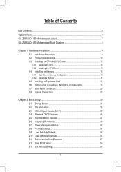
Table of Contents Box Contents...6 Optional Items...6 GA-Z68X-UD4-B3 Motherboard Layout 7 GA-Z68X-UD4-B3 Motherboard Block Diagram 8 Chapter 1 Hardware Installation 9 1-1 Installation Precautions 9 1-2 Product Specifications 10 1-3 Installing the CPU and CPU Cooler ... SLI Configuration 19 1-7 Back Panel Connectors 20 1-8 Internal Connectors 22 Chapter 2 BIOS Setup 33 2-1 Startup Screen 34 2-2 The Main Menu 35 2-3 MB Intelligent Tweaker(M.I.T 37 2-4 Standard CMOS Features 45 2-5 Advanced BIOS Features 47 2-6 Integrated Peripherals 49 2-7 Power Management Setup 52 2-8 PC Health ...
Table of Contents Box Contents...6 Optional Items...6 GA-Z68X-UD4-B3 Motherboard Layout 7 GA-Z68X-UD4-B3 Motherboard Block Diagram 8 Chapter 1 Hardware Installation 9 1-1 Installation Precautions 9 1-2 Product Specifications 10 1-3 Installing the CPU and CPU Cooler ... SLI Configuration 19 1-7 Back Panel Connectors 20 1-8 Internal Connectors 22 Chapter 2 BIOS Setup 33 2-1 Startup Screen 34 2-2 The Main Menu 35 2-3 MB Intelligent Tweaker(M.I.T 37 2-4 Standard CMOS Features 45 2-5 Advanced BIOS Features 47 2-6 Integrated Peripherals 49 2-7 Power Management Setup 52 2-8 PC Health ...
Manual
Page 5
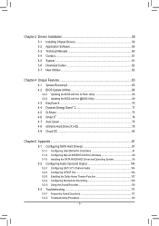
... 60 3-4 Contact...61 3-5 System...61 3-6 Download Center 62 3-7 New Utilities...62 Chapter 4 Unique Features 63 4-1 Xpress Recovery2 63 4-2 BIOS Update Utilities 66 4-2-1 Updating the BIOS with the Q-Flash Utility 66 4-2-2 Updating the BIOS with the @BIOS Utility 69 4-3 EasyTune 6...70 4-4 Dynamic Energy Saver™ 2 71 4-5 Q-Share...73 4-6 Smart 6™ ...74 4-7 Auto Green...78 4-8 eXtreme...
... 60 3-4 Contact...61 3-5 System...61 3-6 Download Center 62 3-7 New Utilities...62 Chapter 4 Unique Features 63 4-1 Xpress Recovery2 63 4-2 BIOS Update Utilities 66 4-2-1 Updating the BIOS with the Q-Flash Utility 66 4-2-2 Updating the BIOS with the @BIOS Utility 69 4-3 EasyTune 6...70 4-4 Dynamic Energy Saver™ 2 71 4-5 Q-Share...73 4-6 Smart 6™ ...74 4-7 Auto Green...78 4-8 eXtreme...
Manual
Page 8
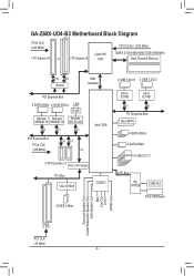
GA-Z68X-UD4-B3 Motherboard Block Diagram PCIe CLK (100 MHz) 1 PCI Express x16 or 2 PCI Express x8 LGA1155 CPU CPU CLK+/- (100 MHz) DDR3 2133/1866/1600/1333/... Express x1 PCIe to PCI Bridge PCI Bus VIA VT6308 CODEC 2 IEEE 1394a 2 USB 3.0/2.0 2 USB 3.0/2.0 Etron EJ168 Etron EJ168 x1 x1 PCI Express Bus Dual BIOS 4 SATA 3Gb/s 2 SATA 6Gb/s 14 USB 2.0/1.1 LPC Bus iTE IT8728 COM Port PS/2 KB/Mouse Surround Speaker Out Center/Subwoofer Speaker Out Side Speaker Out...
GA-Z68X-UD4-B3 Motherboard Block Diagram PCIe CLK (100 MHz) 1 PCI Express x16 or 2 PCI Express x8 LGA1155 CPU CPU CLK+/- (100 MHz) DDR3 2133/1866/1600/1333/... Express x1 PCIe to PCI Bridge PCI Bus VIA VT6308 CODEC 2 IEEE 1394a 2 USB 3.0/2.0 2 USB 3.0/2.0 Etron EJ168 Etron EJ168 x1 x1 PCI Express Bus Dual BIOS 4 SATA 3Gb/s 2 SATA 6Gb/s 14 USB 2.0/1.1 LPC Bus iTE IT8728 COM Port PS/2 KB/Mouse Surround Speaker Out Center/Subwoofer Speaker Out Side Speaker Out...
Manual
Page 12
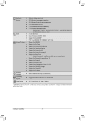
... ŠŠ Use of licensed AWARD BIOS ŠŠ Support for DualBIOS™ ŠŠ PnP 1.0a, DMI 2.0, SM BIOS 2.4, ACPI 1.0b Unique Features ŠŠ Support for @BIOS ŠŠ Support for Q-Flash ŠŠ Support for Xpress BIOS Rescue ŠŠ Support for Download Center...138;Š Support for Microsoft® Windows 7/Vista/XP Form Factor ŠŠ ATX Form Factor; 30.5cm x 24.4cm * GIGABYTE reserves the right to make any changes to the product specifications and product-related information without prior notice. Hardware Installation - 12 - Hardware ...
... ŠŠ Use of licensed AWARD BIOS ŠŠ Support for DualBIOS™ ŠŠ PnP 1.0a, DMI 2.0, SM BIOS 2.4, ACPI 1.0b Unique Features ŠŠ Support for @BIOS ŠŠ Support for Q-Flash ŠŠ Support for Xpress BIOS Rescue ŠŠ Support for Download Center...138;Š Support for Microsoft® Windows 7/Vista/XP Form Factor ŠŠ ATX Form Factor; 30.5cm x 24.4cm * GIGABYTE reserves the right to make any changes to the product specifications and product-related information without prior notice. Hardware Installation - 12 - Hardware ...
Manual
Page 16
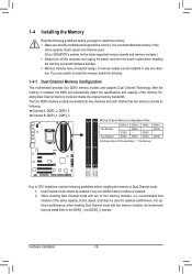
... memory of the same capacity, brand, speed, and chips be installed in Dual Channel mode. 1. A memory module can be used . (Go to GIGABYTE's website for optimum performance. If you install them in the DDR3_1 and DDR3_2 sockets. DS/SS (SS=Single-Sided, DS=Double-Sided, "- -"=No ...DDR3_2 DDR3_3 DDR3_1 Due to CPU limitations, read the following guidelines before installing the memory in only one DDR3 memory module is installed, the BIOS will double the original memory bandwidth. After the memory is installed. 2. The four DDR3 memory sockets are unable to insert the memory,...
... memory of the same capacity, brand, speed, and chips be installed in Dual Channel mode. 1. A memory module can be used . (Go to GIGABYTE's website for optimum performance. If you install them in the DDR3_1 and DDR3_2 sockets. DS/SS (SS=Single-Sided, DS=Double-Sided, "- -"=No ...DDR3_2 DDR3_3 DDR3_1 Due to CPU limitations, read the following guidelines before installing the memory in only one DDR3 memory module is installed, the BIOS will double the original memory bandwidth. After the memory is installed. 2. The four DDR3 memory sockets are unable to insert the memory,...
Manual
Page 18
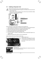
...and press down on the card until it is fully inserted into the slot. 444 Secure the card's metal bracket to make any required BIOS changes for your expansion card(s). 777 Install the driver provided with the expansion card in the expansion slot. 111 Locate an expansion slot that...your expansion card in your expansion card. • Always turn off the computer and unplug the power cord from the slot. If necessary, go to BIOS Setup to the chassis back panel with your operating system. Example: Installing and Removing a PCI Express Graphics Card: • Installing a Graphics Card: ...
...and press down on the card until it is fully inserted into the slot. 444 Secure the card's metal bracket to make any required BIOS changes for your expansion card(s). 777 Install the driver provided with the expansion card in the expansion slot. 111 Locate an expansion slot that...your expansion card in your expansion card. • Always turn off the computer and unplug the power cord from the slot. If necessary, go to BIOS Setup to the chassis back panel with your operating system. Example: Installing and Removing a PCI Express Graphics Card: • Installing a Graphics Card: ...
Manual
Page 24
... is recommended that a system fan be installed inside the chassis. Hardware Installation - 24 - When connecting a fan cable, be sure to keep the values (such as BIOS configurations, date, and time information) in damage to a low level, or the CMOS values may not be accurate or may clear the CMOS values by...
... is recommended that a system fan be installed inside the chassis. Hardware Installation - 24 - When connecting a fan cable, be sure to keep the values (such as BIOS configurations, date, and time information) in damage to a low level, or the CMOS values may not be accurate or may clear the CMOS values by...
Manual
Page 27
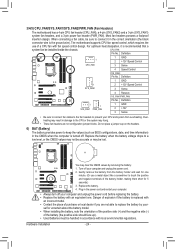
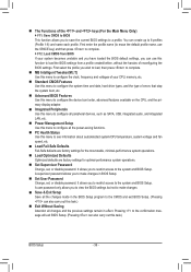
... Yellow/Purple): System Status LED Connects to the hard drive activity LED on the chassis front panel. The LED S0 On is detected, the BIOS may configure the way to turn off (S5). •• PW (Power Switch, Red): Connects to the speaker on the chassis front...Chassis Intrusion Header, Gray): Connects to this header according to indicate the problem. When connecting your system using the power switch (refer to Chapter 2, "BIOS Setup," "Power Management Setup," for information about beep codes. •• HD (Hard Drive Activity LED, Blue) Connects to the power status ...
... Yellow/Purple): System Status LED Connects to the hard drive activity LED on the chassis front panel. The LED S0 On is detected, the BIOS may configure the way to turn off (S5). •• PW (Power Switch, Red): Connects to the speaker on the chassis front...Chassis Intrusion Header, Gray): Connects to this header according to indicate the problem. When connecting your system using the power switch (refer to Chapter 2, "BIOS Setup," "Power Management Setup," for information about beep codes. •• HD (Hard Drive Activity LED, Blue) Connects to the power status ...
Manual
Page 29
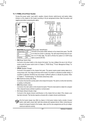
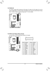
...-OC) - 29 - Definition 11 11 D2+ 2 SSRX1- 12 D2- 3 SSRX1+ 13 GND 4 GND 14 SSTX2+ 5 SSTX1- 15 SSTX2- 6 SSTX1+ 16 GND 7 GND 17 SSRX2+ DB_PORT BIOS 8 D1- 18 SSRX2- 9 D1+ 19 VBUS 10 NC 20 No Pin When the system is in S4/S5 mode, ToPnMly the USB ports routed to...
...-OC) - 29 - Definition 11 11 D2+ 2 SSRX1- 12 D2- 3 SSRX1+ 13 GND 4 GND 14 SSTX2+ 5 SSTX1- 15 SSTX2- 6 SSTX1+ 16 GND 7 GND 17 SSRX2+ DB_PORT BIOS 8 D1- 18 SSRX2- 9 D1+ 19 VBUS 10 NC 20 No Pin When the system is in S4/S5 mode, ToPnMly the USB ports routed to...
Manual
Page 30
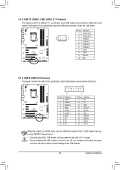
... please con- Ensure that the cable is securely connected. 17) CLR_CMOS (Clearing CMOS Jumper) Use this jumper to factory defaults. date information and BIOS configurations) and reset the CMOS values to clear the CMOS values (e.g. Pin No. Failure to do so may cause damage to the motherboard. &#...device, attach one IEEE 1394a UG T port via an optional IEEE 1394a bracket. 16) F_1394 (IEEE 1394a Header) The header conforms to Chapter 2, "BIOS Setup," for a few seconds. tact the local dealer. To clear the CMOS values, place a jumper cap on your computer and unplug the power ...
... please con- Ensure that the cable is securely connected. 17) CLR_CMOS (Clearing CMOS Jumper) Use this jumper to factory defaults. date information and BIOS configurations) and reset the CMOS values to clear the CMOS values (e.g. Pin No. Failure to do so may cause damage to the motherboard. &#...device, attach one IEEE 1394a UG T port via an optional IEEE 1394a bracket. 16) F_1394 (IEEE 1394a Header) The header conforms to Chapter 2, "BIOS Setup," for a few seconds. tact the local dealer. To clear the CMOS values, place a jumper cap on your computer and unplug the power ...
Manual
Page 31
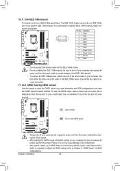
... more the number of lighted LEDs indicates the CPU loading. To enable the Phase LED display function, please first enable Dynamic Energy Saver™ 2. DB_PORT BIOS Switc 1 1 19 TPM w/housing 20 Pin No. 1 2 3 4 5 6 7 8 9 10 Definition LCLK GND LFRAME No Pin LRESET NC LAD3 LAD2 VCC3 LAD1 1 Voltage measurement module(X58A-OC...
... more the number of lighted LEDs indicates the CPU loading. To enable the Phase LED display function, please first enable Dynamic Energy Saver™ 2. DB_PORT BIOS Switc 1 1 19 TPM w/housing 20 Pin No. 1 2 3 4 5 6 7 8 9 10 Definition LCLK GND LFRAME No Pin LRESET NC LAD3 LAD2 VCC3 LAD1 1 Voltage measurement module(X58A-OC...
Manual
Page 33
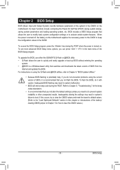
... the power is turned off, the battery on . To upgrade the BIOS, use either the GIGABYTE Q-Flash or @BIOS utility. • Q-Flash allows the user to activate certain system features. To flash the BIOS, do not encounter problems using the current version of BIOS, it with caution. Refer to Chapter 5, "Troubleshooting," for how to clear...
... the power is turned off, the battery on . To upgrade the BIOS, use either the GIGABYTE Q-Flash or @BIOS utility. • Q-Flash allows the user to activate certain system features. To flash the BIOS, do not encounter problems using the current version of BIOS, it with caution. Refer to Chapter 5, "Troubleshooting," for how to clear...
Manual
Page 34
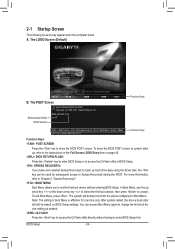
... (C) 1984-2011, Award Software, Inc. Note: The setting in Boot Menu is effective for subsequent access to Xpress Recovery2 during the POST. Motherboard Model BIOS Version Z68X-UD4-B3 F2a . . . . : BIOS Setup : XpressRecovery2 : Boot Menu : Qflash 03/21/2011-Z68-7A89VG0TC-00 Function Keys Function Keys Function Keys: : POST SCREEN Press the key to show...
... (C) 1984-2011, Award Software, Inc. Note: The setting in Boot Menu is effective for subsequent access to Xpress Recovery2 during the POST. Motherboard Model BIOS Version Z68X-UD4-B3 F2a . . . . : BIOS Setup : XpressRecovery2 : Boot Menu : Qflash 03/21/2011-Z68-7A89VG0TC-00 Function Keys Function Keys Function Keys: : POST SCREEN Press the key to show...
Manual
Page 35
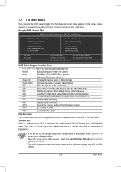
... Exit Without Saving ESC: Quit F8: Q-Flash Select Item F10: Save & Exit Setup Change CPU's Clock & Voltage F11: Save CMOS to BIOS F12: Load CMOS from BIOS BIOS Setup Program Function Keys Move the selection bar to select an item Execute command or enter the submenu Main Menu: Exit the... on-screen description of a highlighted setup option is displayed on the bottom line of function keys available for reference only and may differ by BIOS version. - 35 - BIOS Setup 2-2 The Main Menu Once you want in the Main Menu or a submenu, press + to access more advanced options. •...
... Exit Without Saving ESC: Quit F8: Q-Flash Select Item F10: Save & Exit Setup Change CPU's Clock & Voltage F11: Save CMOS to BIOS F12: Load CMOS from BIOS BIOS Setup Program Function Keys Move the selection bar to select an item Execute command or enter the submenu Main Menu: Exit the... on-screen description of a highlighted setup option is displayed on the bottom line of function keys available for reference only and may differ by BIOS version. - 35 - BIOS Setup 2-2 The Main Menu Once you want in the Main Menu or a submenu, press + to access more advanced options. •...
Manual
Page 36
...supervisor password allows you to restrict access to complete. F12: Load CMOS from a profile created before, without the hassles of reconfiguring the BIOS settings. You can also carry out this task.) Exit Without Saving Abandon all the changes made in effect. First enter the profile name ...(to erase the default profile name, use this function to load the BIOS settings from BIOS If your CPU, memory, etc. Standard CMOS Features Use this menu to configure the system time and date, hard drive types...
...supervisor password allows you to restrict access to complete. F12: Load CMOS from a profile created before, without the hassles of reconfiguring the BIOS settings. You can also carry out this task.) Exit Without Saving Abandon all the changes made in effect. First enter the profile name ...(to erase the default profile name, use this function to load the BIOS settings from BIOS If your CPU, memory, etc. Standard CMOS Features Use this menu to configure the system time and date, hard drive types...

Manual
Page 37
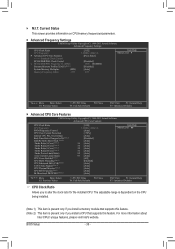
... } Miscellaneous Settings [Press Enter] [Press Enter] [Press Enter] [Press Enter] [Press Enter] Item Help Menu Level BIOS Version BCLK CPU Frequency Memory Frequency Total Memory Size CPU Temperature F2a 99.80 MHz 3094.12 MHz 1332.71 MHz 1024 MB 45oC ... } Miscellaneous Settings [Press Enter] [Press Enter] [Press Enter] [Press Enter] [Press Enter] Item Help Menu Level BIOS Version BCLK CPU Frequency Memory Frequency Total Memory Size CPU Temperature F2a 99.80 MHz 3094.12 MHz 1332.71 MHz 1024 MB 45oC ...
... } Miscellaneous Settings [Press Enter] [Press Enter] [Press Enter] [Press Enter] [Press Enter] Item Help Menu Level BIOS Version BCLK CPU Frequency Memory Frequency Total Memory Size CPU Temperature F2a 99.80 MHz 3094.12 MHz 1332.71 MHz 1024 MB 45oC ... } Miscellaneous Settings [Press Enter] [Press Enter] [Press Enter] [Press Enter] [Press Enter] Item Help Menu Level BIOS Version BCLK CPU Frequency Memory Frequency Total Memory Size CPU Temperature F2a 99.80 MHz 3094.12 MHz 1332.71 MHz 1024 MB 45oC ...
Manual
Page 38
...: Optimized Defaults CPU Clock Ratio Allows you install a CPU that supports this feature. For more information about Intel CPUs' unique features, please visit Intel's website. BIOS Setup - 38 - M.I.T. The adjustable range is present only if you to alter the clock ratio for the installed CPU.
...: Optimized Defaults CPU Clock Ratio Allows you install a CPU that supports this feature. For more information about Intel CPUs' unique features, please visit Intel's website. BIOS Setup - 38 - M.I.T. The adjustable range is present only if you to alter the clock ratio for the installed CPU.


