Manual
Page 1
GA-X38T-DQ6 LGA775 socket motherboard for Intel® CoreTM processor family/ Intel® Pentium® processor family/Intel® Celeron® processor family User's Manual Rev. 1002 12ME-X38TDQ6-1002R
GA-X38T-DQ6 LGA775 socket motherboard for Intel® CoreTM processor family/ Intel® Pentium® processor family/Intel® Celeron® processor family User's Manual Rev. 1002 12ME-X38TDQ6-1002R
Manual
Page 2
Motherboard GA-X38T-DQ6 Sept. 7, 2007 Motherboard GA-X38T-DQ6 Sept. 7, 2007
Motherboard GA-X38T-DQ6 Sept. 7, 2007 Motherboard GA-X38T-DQ6 Sept. 7, 2007
Manual
Page 3
...carefully read the User's Manual. „ For instructions on how to use GIGABYTE's unique features, read or download the information on/from the Support\Motherboard\Technology Guide page on your motherboard revision before updating motherboard BIOS, drivers, or when looking for technical information. No part of this ...order to assist in any form or by copyright laws and is the property of this manual are legally registered to GIGABYTE UNITED INC. Check your motherboard looks like this manual is designated by GIGA-BYTE TECHNOLOGY CO., LTD. Example: is protected by any means without...
...carefully read the User's Manual. „ For instructions on how to use GIGABYTE's unique features, read or download the information on/from the Support\Motherboard\Technology Guide page on your motherboard revision before updating motherboard BIOS, drivers, or when looking for technical information. No part of this ...order to assist in any form or by copyright laws and is the property of this manual are legally registered to GIGABYTE UNITED INC. Check your motherboard looks like this manual is designated by GIGA-BYTE TECHNOLOGY CO., LTD. Example: is protected by any means without...
Manual
Page 4
Table of Contents Box Contents ...6 OptionalItems ...6 GA-X38T-DQ6 Motherboard Layout 7 Block Diagram ...8 Chapter 1 Hardware Installation 9 1-1 Installation Precautions 9 1-2 Product Specifications 10 1-3 Installing the CPU and CPU Cooler 13 1-3-1 Installing the CPU 13 1-3-2 Installing the CPU Cooler 15 1-3-3 Removing the Crazy Cool Heatsink from the Back of the Motherboard ..... 16 1-4 Installing the Memory 17 1-4-1 Dual Channel Memory...
Table of Contents Box Contents ...6 OptionalItems ...6 GA-X38T-DQ6 Motherboard Layout 7 Block Diagram ...8 Chapter 1 Hardware Installation 9 1-1 Installation Precautions 9 1-2 Product Specifications 10 1-3 Installing the CPU and CPU Cooler 13 1-3-1 Installing the CPU 13 1-3-2 Installing the CPU Cooler 15 1-3-3 Removing the Crazy Cool Heatsink from the Back of the Motherboard ..... 16 1-4 Installing the Memory 17 1-4-1 Dual Channel Memory...
Manual
Page 6
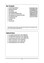
... (Part No. 12CF1-1LP001-01R) - 6 - The box contents are for reference only and the actual items shall depend on product package you obtain. Box Contents GA-X38T-DQ6 motherboard Motherboard driver disk User's Manual Quick Installation Guide Intel® LGA775 CPU Installation Guide One IDE cable and one floppy disk drive cable Four SATA 3Gb...
... (Part No. 12CF1-1LP001-01R) - 6 - The box contents are for reference only and the actual items shall depend on product package you obtain. Box Contents GA-X38T-DQ6 motherboard Motherboard driver disk User's Manual Quick Installation Guide Intel® LGA775 CPU Installation Guide One IDE cable and one floppy disk drive cable Four SATA 3Gb...
Manual
Page 7
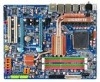
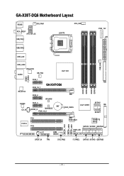
GA-X38T-DQ6 Motherboard Layout KB_MS SYS_FAN1 RCA_SPDIF ATX_12V_2X USB_1394_1 LGA775 CPU_FAN PCIE_12V ATX USB_1394_2 USB_LAN PWR_FAN USB_LAN2 RTL8111B AUDIO NB_FAN Intel® X38 F_AUDIO RTL8111B CODEC CD_IN PCIE_1 PCIE_16_1 GA-X38T-DQ6 PCIE_2 BP_BIOS PCIE_3 BAT SPDIF_O MAIN BIOS PCIE_16_2 CLR_CMOS FDD DDRIII1 DDRIII2 DDRIII3 DDRIII4 Intel® ICH9R SATAII0 IDE SATAII1 PCI1 IT8718 PCI2 CI COM LPT F_1394 F_USB2 F_USB1 TSB43AB23 GIGABYTE SATA2 SATAII4 SATAII2 GSATAIIA PWR_LED SPDIF_IN TPM SYS_FAN2 F_PANEL SATAII5 SATAII3 GSATAIIB - 7 -
GA-X38T-DQ6 Motherboard Layout KB_MS SYS_FAN1 RCA_SPDIF ATX_12V_2X USB_1394_1 LGA775 CPU_FAN PCIE_12V ATX USB_1394_2 USB_LAN PWR_FAN USB_LAN2 RTL8111B AUDIO NB_FAN Intel® X38 F_AUDIO RTL8111B CODEC CD_IN PCIE_1 PCIE_16_1 GA-X38T-DQ6 PCIE_2 BP_BIOS PCIE_3 BAT SPDIF_O MAIN BIOS PCIE_16_2 CLR_CMOS FDD DDRIII1 DDRIII2 DDRIII3 DDRIII4 Intel® ICH9R SATAII0 IDE SATAII1 PCI1 IT8718 PCI2 CI COM LPT F_1394 F_USB2 F_USB1 TSB43AB23 GIGABYTE SATA2 SATAII4 SATAII2 GSATAIIA PWR_LED SPDIF_IN TPM SYS_FAN2 F_PANEL SATAII5 SATAII3 GSATAIIB - 7 -
Manual
Page 9
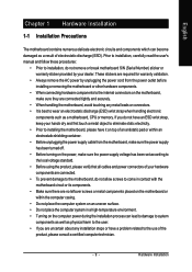
...all cables and power connectors of your hands dry and first touch a metal object to eliminate static electricity. • Prior to installing the motherboard, please have it on top of an antistatic pad or within an electrostatic shielding container. • Before unplugging the power supply cable from the...within the computer casing. • Do not place the computer system on the computer power during the installation process can become damaged as a motherboard, CPU or memory. If you are uncertain about any metal leads or connectors. • It is best to installation, do not allow ...
...all cables and power connectors of your hands dry and first touch a metal object to eliminate static electricity. • Prior to installing the motherboard, please have it on top of an antistatic pad or within an electrostatic shielding container. • Before unplugging the power supply cable from the...within the computer casing. • Do not place the computer system on the computer power during the installation process can become damaged as a motherboard, CPU or memory. If you are uncertain about any metal leads or connectors. • It is best to installation, do not allow ...
Manual
Page 10
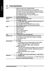
...disk drive connector supporting up to 2 SATA 3Gb/s devices - Support for SATA RAID 0, RAID 1, RAID 5, and RAID 10 Š GIGABYTE SATA2 chip: - 1 x IDE connector supporting ATA-133/100/66/33 and up to 2 IDE devices - 2 x SATA 3Gb/s ...Š Dual channel memory architecture Š Support for DDR3 1600/1333/1066/800 MHz memory modules (Go to GIGABYTE's website for the latest memory support list.) Š Realtek ALC889A codec Š High Definition Audio Š ..., SATAII1, SATAII2, SATAII3, SATAII4, SATAII5) supporting up to the internal IEEE 1394a header) GA-X38T-DQ6 Motherboard - 10 -
...disk drive connector supporting up to 2 SATA 3Gb/s devices - Support for SATA RAID 0, RAID 1, RAID 5, and RAID 10 Š GIGABYTE SATA2 chip: - 1 x IDE connector supporting ATA-133/100/66/33 and up to 2 IDE devices - 2 x SATA 3Gb/s ...Š Dual channel memory architecture Š Support for DDR3 1600/1333/1066/800 MHz memory modules (Go to GIGABYTE's website for the latest memory support list.) Š Realtek ALC889A codec Š High Definition Audio Š ..., SATAII1, SATAII2, SATAII3, SATAII4, SATAII5) supporting up to the internal IEEE 1394a header) GA-X38T-DQ6 Motherboard - 10 -
Manual
Page 12
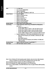
...1) Due to Windows XP 32-bit operating system limitation, when more than 4 GB. (Note 2) Available functions in Easytune may differ by motherboard model. (Note 3) The adjustable CPU voltage range depends on the CPU being used. (Note 4) Due to : - Adjust PCI Express ...- Increase PCIe voltage by 0.05V to 700 MHz with 0.05V increment - Increase FSB voltage by 0.05V to 1.55V with 0.05V increment - GA-X38T-DQ6 Motherboard - 12 - Increase DDR3 voltage by 0.05V to 0.35V with 0.05V increment - English BIOS Unique Features Bundled Software Overclocking Operating System Form Factor ...
...1) Due to Windows XP 32-bit operating system limitation, when more than 4 GB. (Note 2) Available functions in Easytune may differ by motherboard model. (Note 3) The adjustable CPU voltage range depends on the CPU being used. (Note 4) Due to : - Adjust PCI Express ...- Increase PCIe voltage by 0.05V to 700 MHz with 0.05V increment - Increase FSB voltage by 0.05V to 1.55V with 0.05V increment - GA-X38T-DQ6 Motherboard - 12 - Increase DDR3 voltage by 0.05V to 0.35V with 0.05V increment - English BIOS Unique Features Bundled Software Overclocking Operating System Form Factor ...
Manual
Page 13
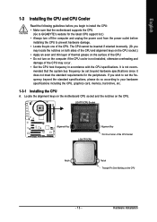
mended that the motherboard supports the CPU. (Go to GIGABYTE's website for the peripherals. Locate the alignment keys on the motherboard CPU socket and the notches on the CPU - 13 - Hardware Installation English 1-3 Installing the CPU and CPU Cooler Read the following guidelines before installing the ...
mended that the motherboard supports the CPU. (Go to GIGABYTE's website for the peripherals. Locate the alignment keys on the motherboard CPU socket and the notches on the CPU - 13 - Hardware Installation English 1-3 Installing the CPU and CPU Cooler Read the following guidelines before installing the ...
Manual
Page 14
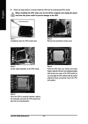
... to turn off the computer and unplug the power cord from the power outlet to prevent damage to correctly install the CPU into the motherboard CPU socket. GA-X38T-DQ6 Motherboard - 14 - CPU Socket Lever Step 1: Completely raise the CPU socket lever. English B. Follow the steps below to the CPU. Step 3: Lift the metal load...
... to turn off the computer and unplug the power cord from the power outlet to prevent damage to correctly install the CPU into the motherboard CPU socket. GA-X38T-DQ6 Motherboard - 14 - CPU Socket Lever Step 1: Completely raise the CPU socket lever. English B. Follow the steps below to the CPU. Step 3: Lift the metal load...
Manual
Page 15
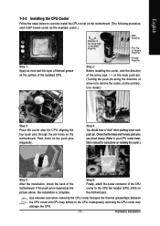
... the push pin is inserted as the example cooler.) Step 1: Apply an even and thin layer of thermal grease on the surface of the motherboard. Inadequately removing the CPU cooler may adhere to the CPU. Push down each push pin. Step 4: You should hear a "click" when pushing... down on the push pins diagonally. English 1-3-2 Installing the CPU Cooler Follow the steps below to correctly install the CPU cooler on the motherboard. (The following procedure uses Intel® boxed cooler as the picture above, the installation is to install.) Step 3: Place the cooler atop ...
... the push pin is inserted as the example cooler.) Step 1: Apply an even and thin layer of thermal grease on the surface of the motherboard. Inadequately removing the CPU cooler may adhere to the CPU. Push down each push pin. Step 4: You should hear a "click" when pushing... down on the push pins diagonally. English 1-3-2 Installing the CPU Cooler Follow the steps below to correctly install the CPU cooler on the motherboard. (The following procedure uses Intel® boxed cooler as the picture above, the installation is to install.) Step 3: Place the cooler atop ...
Manual
Page 16
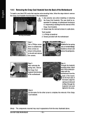
...Cool heatsink. (Note) The components received may vary in appearance from the ones illustrated above. GA-X38T-DQ6 Motherboard - 16 - The Crazy Cool Heatsink Tools needed: 1. Step 5: Do the same for damage of motherboard function(s) or component(s) resulting from the removal of the Crazy Cool heatsink. 2. Screws provided with... when installing or removing the Crazy Cool heatsink. English 1-3-3 Removing the Crazy Cool Heatsink from the Back of the Motherboard To install a non-Intel CPU cooler that requires extra mounting holes, follow the steps below to the left and remove the screws....
...Cool heatsink. (Note) The components received may vary in appearance from the ones illustrated above. GA-X38T-DQ6 Motherboard - 16 - The Crazy Cool Heatsink Tools needed: 1. Step 5: Do the same for damage of motherboard function(s) or component(s) resulting from the removal of the Crazy Cool heatsink. 2. Screws provided with... when installing or removing the Crazy Cool heatsink. English 1-3-3 Removing the Crazy Cool Heatsink from the Back of the Motherboard To install a non-Intel CPU cooler that requires extra mounting holes, follow the steps below to the left and remove the screws....
Manual
Page 17
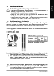
...BIOS will double the original memory bandwidth. When memory modules of the same capacity, brand, speed, and chips be used . (Go to GIGABYTE's website for optimum performance. If you begin to install the memory: • Make sure that memory of the memory. DS/SS DS/...- DS/SS - - DS/SS - - A memory module can be populated and remain in only one DDR3 memory module is recommended that the motherboard supports the memory. English 1-4 Installing the Memory Read the following guidelines before installing the memory to prevent hardware damage. • Memory modules have a...
...BIOS will double the original memory bandwidth. When memory modules of the same capacity, brand, speed, and chips be used . (Go to GIGABYTE's website for optimum performance. If you begin to install the memory: • Make sure that memory of the memory. DS/SS DS/...- DS/SS - - DS/SS - - A memory module can be populated and remain in only one DDR3 memory module is recommended that the motherboard supports the memory. English 1-4 Installing the Memory Read the following guidelines before installing the memory to prevent hardware damage. • Memory modules have a...
Manual
Page 18
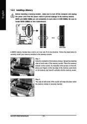
... 2: The clips at both ends of the socket will snap into the memory socket. GA-X38T-DQ6 Motherboard - 18 - Step 1: Note the orientation of the memory module. DDR3 and DDR2 DIMMs are not compatible to each other or DDR DIMMs. Be sure to ...
... 2: The clips at both ends of the socket will snap into the memory socket. GA-X38T-DQ6 Motherboard - 18 - Step 1: Note the orientation of the memory module. DDR3 and DDR2 DIMMs are not compatible to each other or DDR DIMMs. Be sure to ...
Manual
Page 19
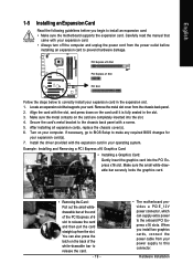
...8226; Removing the Card: Pull out the small whitedrawable bar at the end of the white-drawable bar to release the card. - 19 - • The motherboard provides a PCIE_12V power connector, which can also press the latch on your operating system. You can supply extra power to release the card and then... slot cover from your power supply to this connector. If necessary, go to BIOS Setup to install an expansion card: • Make sure the motherboard supports the expansion card. Align the card with a screw. 5. PCI Express x16 Slot PCI Express x1 Slot PCI Slot Follow the steps below to...
...8226; Removing the Card: Pull out the small whitedrawable bar at the end of the white-drawable bar to release the card. - 19 - • The motherboard provides a PCIE_12V power connector, which can also press the latch on your operating system. You can supply extra power to release the card and then... slot cover from your power supply to this connector. If necessary, go to BIOS Setup to install an expansion card: • Make sure the motherboard supports the expansion card. Align the card with a screw. 5. PCI Express x16 Slot PCI Express x1 Slot PCI Slot Follow the steps below to...
Manual
Page 20
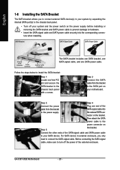
...includes one SATA bracket, one SATA signal cable, and one free PCI slot and secure the SATA bracket to the power connector on your motherboard. Before connecting the SATA signal cable, make sure to connect the SATA signal cable. For SATA device in external enclosure, you to ... Connect the power Plug one end of the SATA signal cable and SATA power cable to your system and the power switch on the bracket. GA-X38T-DQ6 Motherboard - 20 - Follow the steps below to install the SATA bracket: Step 1: Locate one SATA power cable. nector on the power supply before ...
...includes one SATA bracket, one SATA signal cable, and one free PCI slot and secure the SATA bracket to the power connector on your motherboard. Before connecting the SATA signal cable, make sure to connect the SATA signal cable. For SATA device in external enclosure, you to ... Connect the power Plug one end of the SATA signal cable and SATA power cable to your system and the power switch on the bracket. GA-X38T-DQ6 Motherboard - 20 - Follow the steps below to install the SATA bracket: Step 1: Locate one SATA power cable. nector on the power supply before ...
Manual
Page 21
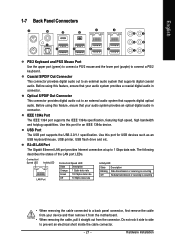
... Port The Gigabit Ethernet LAN port provides Internet connection at up to an external audio system that your device and then remove it from the motherboard. • When removing the cable, pull it side to side to an external audio system that your audio system provides a coaxial digital audio in connector...
... Port The Gigabit Ethernet LAN port provides Internet connection at up to an external audio system that your device and then remove it from the motherboard. • When removing the cable, pull it side to side to an external audio system that your audio system provides a coaxial digital audio in connector...
Manual
Page 22
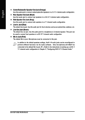
... in a 4/5.1/7.1-channel audio configuration. Line Out Jack (Green) The default line out jack. Microphones must be reconfigured to perform different functions via the audio software. GA-X38T-DQ6 Motherboard - 22 - English Center/Subwoofer Speaker Out Jack (Orange) Use this audio jack to connect center/subwoofer speakers in a 7.1-channel audio configuration. Rear Speaker Out Jack...
... in a 4/5.1/7.1-channel audio configuration. Line Out Jack (Green) The default line out jack. Microphones must be reconfigured to perform different functions via the audio software. GA-X38T-DQ6 Motherboard - 22 - English Center/Subwoofer Speaker Out Jack (Orange) Use this audio jack to connect center/subwoofer speakers in a 7.1-channel audio configuration. Rear Speaker Out Jack...
Manual
Page 23
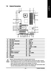
... devices and your devices are compliant with the connectors you wish to connect. • Before installing the devices, be sure to the connector on the motherboard. - 23 -
... devices and your devices are compliant with the connectors you wish to connect. • Before installing the devices, be sure to the connector on the motherboard. - 23 -


