Manual
Page 4
...Heatsink from the Back of the Motherboard ..... 16 1-4 Installing the Memory 17 1-4-1 Dual Channel Memory Configuration 17 1-4-2 Installing a Memory 18 1-5 Installing an Expansion Card 19 1-6 Installing the SATA Bracket 20 1-7 Back Panel Connectors 21 1-8 Internal Connectors 23 Chapter 2 BIOS Setup 37 2-1 Startup Screen 38 2-2 The Main Menu 39 2-3 Standard CMOS Features 41 2-4 Advanced BIOS Features 43 2-5 IntegratedPeripherals 45 2-6 Power Management Setup 49 2-7 PnP/PCI Configurations 51 2-8 PC Health Status 52 2-9 MB Intelligent Tweaker(M.I.T 54 2-10 Load Fail-Safe Defaults...
...Heatsink from the Back of the Motherboard ..... 16 1-4 Installing the Memory 17 1-4-1 Dual Channel Memory Configuration 17 1-4-2 Installing a Memory 18 1-5 Installing an Expansion Card 19 1-6 Installing the SATA Bracket 20 1-7 Back Panel Connectors 21 1-8 Internal Connectors 23 Chapter 2 BIOS Setup 37 2-1 Startup Screen 38 2-2 The Main Menu 39 2-3 Standard CMOS Features 41 2-4 Advanced BIOS Features 43 2-5 IntegratedPeripherals 45 2-6 Power Management Setup 49 2-7 PnP/PCI Configurations 51 2-8 PC Health Status 52 2-9 MB Intelligent Tweaker(M.I.T 54 2-10 Load Fail-Safe Defaults...
Manual
Page 10
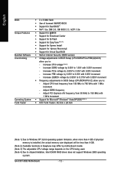
...and up to 2 IDE devices - 2 x SATA 3Gb/s connectors (GSATAIIA, GSATAIIB) supporting up to 2 SATA 3Gb/s devices - Support for CD In Š 2 x Realtek 8111B chips (10/100/1000 Mbit) Š 2 x PCI Express x16 slots supporting ATI CrossFireTM technology (The PCI Express x16 slots conform to PCI Express 2.0 standard.) Š 3 x PCI Express x1 slots Š 2 x PCI slots Š South Bridge: - 6 x SATA 3Gb/s connectors (SATAII0, SATAII1, SATAII2, SATAII3, SATAII4, SATAII5) supporting up to the internal IEEE 1394a header) GA-X38T-DQ6 Motherboard - 10 - Support for SATA RAID 0, RAID 1, and JBOD...
...and up to 2 IDE devices - 2 x SATA 3Gb/s connectors (GSATAIIA, GSATAIIB) supporting up to 2 SATA 3Gb/s devices - Support for CD In Š 2 x Realtek 8111B chips (10/100/1000 Mbit) Š 2 x PCI Express x16 slots supporting ATI CrossFireTM technology (The PCI Express x16 slots conform to PCI Express 2.0 standard.) Š 3 x PCI Express x1 slots Š 2 x PCI slots Š South Bridge: - 6 x SATA 3Gb/s connectors (SATAII0, SATAII1, SATAII2, SATAII3, SATAII4, SATAII5) supporting up to the internal IEEE 1394a header) GA-X38T-DQ6 Motherboard - 10 - Support for SATA RAID 0, RAID 1, and JBOD...
Manual
Page 12
...; Support for Virtual Dual BIOS Š Norton Internet Security (OEM version) Š Voltage adjustments in BIOS Setup (CPU/DDR3/PCIe/FSB/(G)MCH) allow you to 150 MHz with 0.05V increment - Adjust DDR3 frequency - GA-X38T-DQ6 Motherboard - 12 - Increase CPU voltage (Note 3) - Adjust PCI Express x16 frequency from 100 MHz to chipset limitation, Intel ICH9R RAID driver does not support Windows 2000 operating system. Increase DDR3 voltage by motherboard model. (Note 3) The adjustable CPU voltage range depends on the CPU being used...
...; Support for Virtual Dual BIOS Š Norton Internet Security (OEM version) Š Voltage adjustments in BIOS Setup (CPU/DDR3/PCIe/FSB/(G)MCH) allow you to 150 MHz with 0.05V increment - Adjust DDR3 frequency - GA-X38T-DQ6 Motherboard - 12 - Increase CPU voltage (Note 3) - Adjust PCI Express x16 frequency from 100 MHz to chipset limitation, Intel ICH9R RAID driver does not support Windows 2000 operating system. Increase DDR3 voltage by motherboard model. (Note 3) The adjustable CPU voltage range depends on the CPU being used...
Manual
Page 19
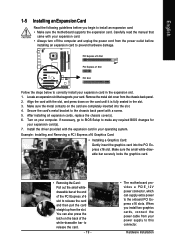
... motherboard supports the expansion card. English 1-5 Installing an Expansion Card Read the following guidelines before installing an expansion card to the onboard PCI Express x16 slots. Carefully read the manual that supports your operating system. After installing all expansion cards, replace the chassis cover(s). 6. Install the driver provided with the slot, and press down on the back of the PCI Express x16 slot to make any required BIOS changes for your computer. You can supply extra power...
... motherboard supports the expansion card. English 1-5 Installing an Expansion Card Read the following guidelines before installing an expansion card to the onboard PCI Express x16 slots. Carefully read the manual that supports your operating system. After installing all expansion cards, replace the chassis cover(s). 6. Install the driver provided with the slot, and press down on the back of the PCI Express x16 slot to make any required BIOS changes for your computer. You can supply extra power...
Manual
Page 25
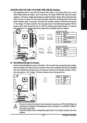
...Most fans are not configuration jumper blocks. The motherboard supports CPU fan speed control, which requires the use of a CPU fan with color-coded power connector wires. Definition 1 GND 2 +12V / Speed Control 3 Sense 4 Speed Control 1 SYS_FAN1 1 PWR_FAN SYS_FAN1 / PWR_FAN : Pin No. A red power connector wire indicates a positive connection and requires a +12V voltage. Definition 1 GND 2 +12V 3 NC • Be sure to connect fan cables to the fan headers to this header. The black connector wire is recommended that a system fan be installed inside the chassis...
...Most fans are not configuration jumper blocks. The motherboard supports CPU fan speed control, which requires the use of a CPU fan with color-coded power connector wires. Definition 1 GND 2 +12V / Speed Control 3 Sense 4 Speed Control 1 SYS_FAN1 1 PWR_FAN SYS_FAN1 / PWR_FAN : Pin No. A red power connector wire indicates a positive connection and requires a +12V voltage. Definition 1 GND 2 +12V 3 NC • Be sure to connect fan cables to the fan headers to this header. The black connector wire is recommended that a system fan be installed inside the chassis...
Manual
Page 43
... Options are: Floppy, LS120, Hard Disk, CDROM, ZIP, USB-FDD, USB-ZIP, USB-CDROM, USB-HDD, Legacy LAN, Disabled. This feature allows your system to report read/write errors of the hard drive and to 3 (Note) No-Execute Memory Protect (Note) CPU Enhanced Halt (C1E) (Note) CPU Thermal Monitor 2(TM2) (Note) CPU EIST Function (Note) Virtualization Technology (Note) Full Screen LOGO Show Init Display First [Press Enter] [Floppy] [Hard Disk] [CDROM] [Setup] [Disabled] [Enabled] [Disabled] [Enabled] [Enabled] [Enabled] [Enabled] [Enabled] [Enabled] [PCI] Item Help Menu Level` KLJI: Move Enter...
... Options are: Floppy, LS120, Hard Disk, CDROM, ZIP, USB-FDD, USB-ZIP, USB-CDROM, USB-HDD, Legacy LAN, Disabled. This feature allows your system to report read/write errors of the hard drive and to 3 (Note) No-Execute Memory Protect (Note) CPU Enhanced Halt (C1E) (Note) CPU Thermal Monitor 2(TM2) (Note) CPU EIST Function (Note) Virtualization Technology (Note) Full Screen LOGO Show Init Display First [Press Enter] [Floppy] [Hard Disk] [CDROM] [Setup] [Disabled] [Enabled] [Disabled] [Enabled] [Enabled] [Enabled] [Enabled] [Enabled] [Enabled] [PCI] Item Help Menu Level` KLJI: Move Enter...

Manual
Page 44
... using an Intel® CPU that supports multi-core technology. to 3 (Note) Allows you to determine whether to limit CPUID maximum value. With virtualization, one CPU core. GA-X38T-DQ6 Motherboard - 44 - set this item to Enabled for Windows XP operating system; Disabled displays normal POST message. (Default: Enabled) Init Display First Specifies the first initiation of the monitor display from the installed PCI graphics card or the PCI Express graphics card. PCI Sets the PCI graphics card as the first display. (Default) PEG Sets PCI Express graphics card on CPU loading...
... using an Intel® CPU that supports multi-core technology. to 3 (Note) Allows you to determine whether to limit CPUID maximum value. With virtualization, one CPU core. GA-X38T-DQ6 Motherboard - 44 - set this item to Enabled for Windows XP operating system; Disabled displays normal POST message. (Default: Enabled) Init Display First Specifies the first initiation of the monitor display from the installed PCI graphics card or the PCI Express graphics card. PCI Sets the PCI graphics card as the first display. (Default) PEG Sets PCI Express graphics card on CPU loading...

Manual
Page 45
... Setup Utility-Copyright (C) 1984-2007 Award Software Integrated Peripherals SATA RAID/AHCI Mode SATA Port0~3 Native Mode USB Controller USB 2.0 Controller USB Keyboard Support USB Mouse Support Legacy USB storage detect Azalia Codec Onboard H/W 1394 Onboard H/W LAN1 Onboard H/W LAN2 ` SMART LAN1 ` SMART LAN2 Onboard LAN1 Boot ROM Onboard LAN2 Boot ROM Onboard SATA/IDE Device Onboard SATA/IDE Ctrl Mode Onboard Serial Port 1 Onboard Parallel Port [Disabled] [Disabled] [Enabled] [Enabled] [Disabled] [Disabled] [Enabled] [Auto] [Enabled] [Enabled] [Enabled] [Press Enter] [Press Enter] [Disabled...
... Setup Utility-Copyright (C) 1984-2007 Award Software Integrated Peripherals SATA RAID/AHCI Mode SATA Port0~3 Native Mode USB Controller USB 2.0 Controller USB Keyboard Support USB Mouse Support Legacy USB storage detect Azalia Codec Onboard H/W 1394 Onboard H/W LAN1 Onboard H/W LAN2 ` SMART LAN1 ` SMART LAN2 Onboard LAN1 Boot ROM Onboard LAN2 Boot ROM Onboard SATA/IDE Device Onboard SATA/IDE Ctrl Mode Onboard Serial Port 1 Onboard Parallel Port [Disabled] [Disabled] [Enabled] [Enabled] [Disabled] [Disabled] [Enabled] [Auto] [Enabled] [Enabled] [Enabled] [Press Enter] [Press Enter] [Disabled...
Manual
Page 48
... RAID for the SATA controller and configures the SATA controller to PATA mode. (Default) AHCI Configures the SATA controller to enable advanced Serial ATA features such as Native Command Queuing and hot plug. GA-X38T-DQ6 Motherboard - 48 - English Onboard LAN1 Boot ROM (LAN port) Allows you to decide whether to activate the boot ROM integrated with the onboard LAN chip. (Default: Disabled) Onboard LAN2 Boot ROM (LAN2 port) Allows you to decide whether to activate the boot ROM integrated with the onboard LAN chip. (Default: Disabled) Onboard SATA/IDE Device (GIGABYTE SATA2 Chip...
... RAID for the SATA controller and configures the SATA controller to PATA mode. (Default) AHCI Configures the SATA controller to enable advanced Serial ATA features such as Native Command Queuing and hot plug. GA-X38T-DQ6 Motherboard - 48 - English Onboard LAN1 Boot ROM (LAN port) Allows you to decide whether to activate the boot ROM integrated with the onboard LAN chip. (Default: Disabled) Onboard LAN2 Boot ROM (LAN2 port) Allows you to decide whether to activate the boot ROM integrated with the onboard LAN chip. (Default: Disabled) Onboard SATA/IDE Device (GIGABYTE SATA2 Chip...
Manual
Page 53
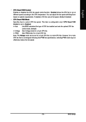
If disabled, CPU fan runs at different speed according to the CPU temperature. Auto Lets BIOS autodetect the type of CPU fan installed and sets the optimal CPU fan control mode. (Default) Voltage Sets Voltage mode for a 3-pin CPU fan or a 4-pin CPU fan. Note: The Voltage mode can adjust the fan speed with EasyTune based on system requirements. BIOS Setup However, for a 4-pin CPU fan. You can be set to control CPU fan speed. This item is configurable only if CPU Smart FAN Control is not designed following Intel PWM fan specifications, selecting PWM mode may not ...
If disabled, CPU fan runs at different speed according to the CPU temperature. Auto Lets BIOS autodetect the type of CPU fan installed and sets the optimal CPU fan control mode. (Default) Voltage Sets Voltage mode for a 3-pin CPU fan or a 4-pin CPU fan. Note: The Voltage mode can adjust the fan speed with EasyTune based on system requirements. BIOS Setup However, for a 4-pin CPU fan. You can be set to control CPU fan speed. This item is configurable only if CPU Smart FAN Control is not designed following Intel PWM fan specifications, selecting PWM mode may not ...
Manual
Page 55
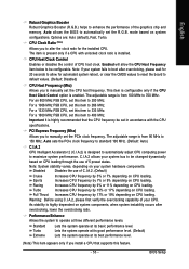
... configurable only if the CPU Host Clock Control option is designed to automatically adjust CPU computing power to default values. (Default: Disabled) CPU Host Frequency (Mhz) Allows you install a CPU that the CPU frequency be set the CPU host frequency. For a 1600 MHz FSB CPU, set the R.G.B. Important It is highly recommended that supports this feature. - 55 - PCI Express Frequency (Mhz) Allows you to alter the clock ratio for automated system reboot, or clear the CMOS values to reset the board...
... configurable only if the CPU Host Clock Control option is designed to automatically adjust CPU computing power to default values. (Default: Disabled) CPU Host Frequency (Mhz) Allows you install a CPU that the CPU frequency be set the CPU host frequency. For a 1600 MHz FSB CPU, set the R.G.B. Important It is highly recommended that supports this feature. - 55 - PCI Express Frequency (Mhz) Allows you to alter the clock ratio for automated system reboot, or clear the CMOS values to reset the board...
Manual
Page 60
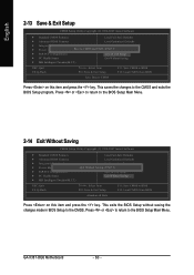
... the key. GA-X38T-DQ6 Motherboard - 60 - This exits the BIOS Setup without saving the changes made in BIOS Setup to the CMOS and exits the BIOS Setup program. Press or to return to the BIOS Setup Main Menu. English 2-13 Save & Exit Setup CMOS Setup Utility-Copyright (C) 1984-2007 Award Software ` Standard CMOS Features Load Fail-Safe Defaults ` Advanced BIOS Features Load Optimized Defaults ` Integrated Peripherals Set Supervisor Password ` Power Management Setup Save to CMOS and EXIT (SYe/tNU)?seYr Password ` PnP/PCI Configurations Save & Exit Setup ` PC...
... the key. GA-X38T-DQ6 Motherboard - 60 - This exits the BIOS Setup without saving the changes made in BIOS Setup to the CMOS and exits the BIOS Setup program. Press or to return to the BIOS Setup Main Menu. English 2-13 Save & Exit Setup CMOS Setup Utility-Copyright (C) 1984-2007 Award Software ` Standard CMOS Features Load Fail-Safe Defaults ` Advanced BIOS Features Load Optimized Defaults ` Integrated Peripherals Set Supervisor Password ` Power Management Setup Save to CMOS and EXIT (SYe/tNU)?seYr Password ` PnP/PCI Configurations Save & Exit Setup ` PC...
Manual
Page 77
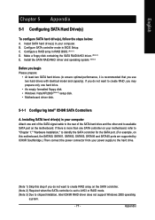
... not support Windows 2000 operating system. - 77 - Make a floppy disk containing the SATA RAID/AHCI driver. (Note 2) E. C . If there is set to AHCI or RAID mode. (Note 3) Due to available SATA port on this step if you use two hard drives with identical model and capacity). Install SATA hard drive(s) in your computer Attach one SATA controller on your motherboard, refer to "Chapter 1," "Hardware Installation," to identify the SATA controller for the SATA port. (For example, on the motherboard. Configure a RAID array in BIOS Setup. Installing SATA hard drive...
... not support Windows 2000 operating system. - 77 - Make a floppy disk containing the SATA RAID/AHCI driver. (Note 2) E. C . If there is set to AHCI or RAID mode. (Note 3) Due to available SATA port on this step if you use two hard drives with identical model and capacity). Install SATA hard drive(s) in your computer Attach one SATA controller on your motherboard, refer to "Chapter 1," "Hardware Installation," to identify the SATA controller for the SATA port. (For example, on the motherboard. Configure a RAID array in BIOS Setup. Installing SATA hard drive...
Manual
Page 78
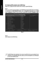
... and the BIOS version. CMOS Setup Utility-Copyright (C) 1984-2007 Award Software Integrated Peripherals SATA RAID/AHCI Mode SATA Port0~3 Native Mode USB Controller USB 2.0 Controller USB Keyboard Support USB Mouse Support Legacy USB storage detect Azalia Codec Onboard H/W 1394 Onboard H/W LAN1 Onboard H/W LAN2 ` SMART LAN1 ` SMART LAN2 Onboard LAN1 Boot ROM Onboard LAN2 Boot ROM Onboard SATA/IDE Device Onboard SATA/IDE Ctrl Mode Onboard Serial Port 1 Onboard Parallel Port [RAID] [Disabled] [Enabled] [Enabled] [Disabled] [Disabled] [Enabled] [Auto] [Enabled] [Enabled] [Enabled] [Press Enter...
... and the BIOS version. CMOS Setup Utility-Copyright (C) 1984-2007 Award Software Integrated Peripherals SATA RAID/AHCI Mode SATA Port0~3 Native Mode USB Controller USB 2.0 Controller USB Keyboard Support USB Mouse Support Legacy USB storage detect Azalia Codec Onboard H/W 1394 Onboard H/W LAN1 Onboard H/W LAN2 ` SMART LAN1 ` SMART LAN2 Onboard LAN1 Boot ROM Onboard LAN2 Boot ROM Onboard SATA/IDE Device Onboard SATA/IDE Ctrl Mode Onboard Serial Port 1 Onboard Parallel Port [RAID] [Disabled] [Enabled] [Enabled] [Disabled] [Disabled] [Enabled] [Auto] [Enabled] [Enabled] [Enabled] [Press Enter...
Manual
Page 83
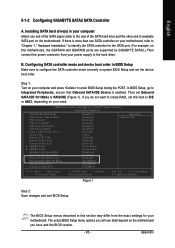
... SATA Controller A. Installing SATA hard drive(s) in system BIOS Setup and set the device boot order. CMOS Setup Utility-Copyright (C) 1984-2007 Award Software Integrated Peripherals SATA RAID/AHCI Mode SATA Port0~3 Native Mode USB Controller USB 2.0 Controller USB Keyboard Support USB Mouse Support Legacy USB storage detect Azalia Codec Onboard H/W 1394 Onboard H/W LAN1 Onboard H/W LAN2 ` SMART LAN1 ` SMART LAN2 Onboard LAN1 Boot ROM Onboard LAN2 Boot ROM Onboard SATA/IDE Device Onboard SATA/IDE Ctrl Mode Onboard Serial Port 1 Onboard Parallel Port [Disabled] [Disabled] [Enabled] [Enabled...
... SATA Controller A. Installing SATA hard drive(s) in system BIOS Setup and set the device boot order. CMOS Setup Utility-Copyright (C) 1984-2007 Award Software Integrated Peripherals SATA RAID/AHCI Mode SATA Port0~3 Native Mode USB Controller USB 2.0 Controller USB Keyboard Support USB Mouse Support Legacy USB storage detect Azalia Codec Onboard H/W 1394 Onboard H/W LAN1 Onboard H/W LAN2 ` SMART LAN1 ` SMART LAN2 Onboard LAN1 Boot ROM Onboard LAN2 Boot ROM Onboard SATA/IDE Device Onboard SATA/IDE Ctrl Mode Onboard Serial Port 1 Onboard Parallel Port [Disabled] [Disabled] [Enabled] [Enabled...
Manual
Page 84
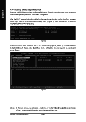
... [ Main Menu ] [ Hard Disk Drive List ] Create RAID Disk Drive Delete RAID Disk Drive Revert HDD to Non-RAID Solve Mirror Conflict Rebuild Mirror Drive Save And Exit Setup Exit Without Saving Model Name HDD0: ST3120026AS HDD1: ST3120026AS Capacity 120 GB 120 GB Type/Status Non-RAID Non-RAID [ RAID Disk Drive List ] [IJTAB]-Switch Window [KL]-Select ITEM [ENTER]-Action Figure 3 [ESC]-Exit (Note) In the main screen, you wish to execute and press . GA-X38T-DQ6 Motherboard - 84 - After the POST memory test...
... [ Main Menu ] [ Hard Disk Drive List ] Create RAID Disk Drive Delete RAID Disk Drive Revert HDD to Non-RAID Solve Mirror Conflict Rebuild Mirror Drive Save And Exit Setup Exit Without Saving Model Name HDD0: ST3120026AS HDD1: ST3120026AS Capacity 120 GB 120 GB Type/Status Non-RAID Non-RAID [ RAID Disk Drive List ] [IJTAB]-Switch Window [KL]-Select ITEM [ENTER]-Action Figure 3 [ESC]-Exit (Note) In the main screen, you wish to execute and press . GA-X38T-DQ6 Motherboard - 84 - After the POST memory test...
Manual
Page 89
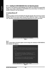
... GIGABYTE SATA2 SATA controller, select E) GIGABYTE SATA-RAID Driver 32Bit for Windows 32-bit operating system or F) GIGABYTE SATA-RAID Driver 64Bit for Windows 64-bit. Once at the A:\> prompt, change to exit when finished. Press after each command (Figure 1): cd bootdrv menu Step 2: When the controller menu (Figure 2) appears, remove the startup disk and insert the blank formatted disk. Boot from the motherboard driver disk to a floppy disk. For example, from the menu. Figure 3 - 89 - At the D:\> prompt, type...
... GIGABYTE SATA2 SATA controller, select E) GIGABYTE SATA-RAID Driver 32Bit for Windows 32-bit operating system or F) GIGABYTE SATA-RAID Driver 64Bit for Windows 64-bit. Once at the A:\> prompt, change to exit when finished. Press after each command (Figure 1): cd bootdrv menu Step 2: When the controller menu (Figure 2) appears, remove the startup disk and insert the blank formatted disk. Boot from the motherboard driver disk to a floppy disk. For example, from the menu. Figure 3 - 89 - At the D:\> prompt, type...
Manual
Page 90
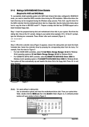
... Device ENTER=Continue F3=Exit Figure 2 GA-X38T-DQ6 Motherboard - 90 - The following mass storage devices(s) * To specify additional SCSI adapters, CD-ROM drives, or special disk controllers for use with Windows, including those for which you have a device support disk from a mass storage device manufacturer, press S. * If you do not want to specify additional mass storage devices for use with Windows, press ENTER. Installing Windows XP Step 1: Restart your system, or you have chosen to manually...
... Device ENTER=Continue F3=Exit Figure 2 GA-X38T-DQ6 Motherboard - 90 - The following mass storage devices(s) * To specify additional SCSI adapters, CD-ROM drives, or special disk controllers for use with Windows, including those for which you have a device support disk from a mass storage device manufacturer, press S. * If you do not want to specify additional mass storage devices for use with Windows, press ENTER. Installing Windows XP Step 1: Restart your system, or you have chosen to manually...

Manual
Page 103
... front panel and back panel cannot be output from the S/PDIF OUT. 5-2-4 Configuring Microphone Recording Step 1: After installing the audio driver, the Audio Manager icon will appear in your system tray. Step 3: Locate the Volume icon in your system tray and click it to be used at the same time. Digital PCM Output Setup: In the Audio Control Panel, click the Audio I/O tab. Enable this...
... front panel and back panel cannot be output from the S/PDIF OUT. 5-2-4 Configuring Microphone Recording Step 1: After installing the audio driver, the Audio Manager icon will appear in your system tray. Step 3: Locate the Volume icon in your system tray and click it to be used at the same time. Digital PCM Output Setup: In the Audio Control Panel, click the Audio I/O tab. Enable this...
Manual
Page 108
... on after the computer shuts down ? Turn off your computer. 5. A: The following Award BIOS beep code descriptions may help you identify possible computer problems. (For reference only.) 1 short: System boots successfully 2 short: CMOS setting error 1 long, 1 short: Memory or motherboard error 1 long, 2 short: Monitor or graphics card error 1 long, 3 short: Keyboard error 1 long, 9 short: BIOS ROM error Continuous long beeps: Graphics card not inserted properly Continuous short beeps: Power error GA-X38T-DQ6 Motherboard - 108 - Q: In the BIOS Setup program, why are hidden in Chapter...
... on after the computer shuts down ? Turn off your computer. 5. A: The following Award BIOS beep code descriptions may help you identify possible computer problems. (For reference only.) 1 short: System boots successfully 2 short: CMOS setting error 1 long, 1 short: Memory or motherboard error 1 long, 2 short: Monitor or graphics card error 1 long, 3 short: Keyboard error 1 long, 9 short: BIOS ROM error Continuous long beeps: Graphics card not inserted properly Continuous short beeps: Power error GA-X38T-DQ6 Motherboard - 108 - Q: In the BIOS Setup program, why are hidden in Chapter...


