Manual
Page 3
...In order to assist in this manual are legally registered to the specifications and features in this manual may be made by GIGABYTE without GIGABYTE's prior written permission. Example: Copyright © 2007 GIGA-BYTE TECHNOLOGY CO., LTD. by any means without prior notice....motherboard revision before updating motherboard BIOS, drivers, or when looking for technical information. No part of this product, GIGABYTE provides the following types of documentations: „ For quick set-up of GIGABYTE. For example, "REV: 1.0" means the revision of GIGABYTE branded motherboards. The logo ...
...In order to assist in this manual are legally registered to the specifications and features in this manual may be made by GIGABYTE without GIGABYTE's prior written permission. Example: Copyright © 2007 GIGA-BYTE TECHNOLOGY CO., LTD. by any means without prior notice....motherboard revision before updating motherboard BIOS, drivers, or when looking for technical information. No part of this product, GIGABYTE provides the following types of documentations: „ For quick set-up of GIGABYTE. For example, "REV: 1.0" means the revision of GIGABYTE branded motherboards. The logo ...
Manual
Page 4
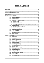
Table of Contents Box Contents ...6 OptionalItems ...6 GA-X38T-DQ6 Motherboard Layout 7 Block Diagram ...8 Chapter 1 Hardware Installation 9 1-1 Installation Precautions 9 1-2 Product Specifications 10 1-3 Installing the CPU and CPU Cooler 13 ... Card 19 1-6 Installing the SATA Bracket 20 1-7 Back Panel Connectors 21 1-8 Internal Connectors 23 Chapter 2 BIOS Setup 37 2-1 Startup Screen 38 2-2 The Main Menu 39 2-3 Standard CMOS Features 41 2-4 Advanced BIOS Features 43 2-5 IntegratedPeripherals 45 2-6 Power Management Setup 49 2-7 PnP/PCI Configurations 51 2-8 PC Health Status...
Table of Contents Box Contents ...6 OptionalItems ...6 GA-X38T-DQ6 Motherboard Layout 7 Block Diagram ...8 Chapter 1 Hardware Installation 9 1-1 Installation Precautions 9 1-2 Product Specifications 10 1-3 Installing the CPU and CPU Cooler 13 ... Card 19 1-6 Installing the SATA Bracket 20 1-7 Back Panel Connectors 21 1-8 Internal Connectors 23 Chapter 2 BIOS Setup 37 2-1 Startup Screen 38 2-2 The Main Menu 39 2-3 Standard CMOS Features 41 2-4 Advanced BIOS Features 43 2-5 IntegratedPeripherals 45 2-6 Power Management Setup 49 2-7 PnP/PCI Configurations 51 2-8 PC Health Status...
Manual
Page 5
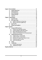
... 63 3-5 Contact Us ...63 Chapter 4 Unique Features 65 4-1 Xpress Recovery2 65 4-2 BIOS Update Utilities 70 4-2-1 Updating the BIOS with the Q-Flash Utility 70 4-2-2 Updating the BIOS with the @BIOS Utility 73 4-3 EasyTune 5 Pro 75 4-4 Windows Vista ReadyBoost 76 Chapter 5 Appendix ...77... 5-1 Configuring SATA Hard Drive(s 77 5-1-1 Configuring Intel® ICH9R SATA Controllers 77 5-1-2 Configuring GIGABYTE SATA2 SATA Controller 83 5-1-3 ...
... 63 3-5 Contact Us ...63 Chapter 4 Unique Features 65 4-1 Xpress Recovery2 65 4-2 BIOS Update Utilities 70 4-2-1 Updating the BIOS with the Q-Flash Utility 70 4-2-2 Updating the BIOS with the @BIOS Utility 73 4-3 EasyTune 5 Pro 75 4-4 Windows Vista ReadyBoost 76 Chapter 5 Appendix ...77... 5-1 Configuring SATA Hard Drive(s 77 5-1-1 Configuring Intel® ICH9R SATA Controllers 77 5-1-2 Configuring GIGABYTE SATA2 SATA Controller 83 5-1-3 ...
Manual
Page 7
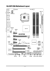
GA-X38T-DQ6 Motherboard Layout KB_MS SYS_FAN1 RCA_SPDIF ATX_12V_2X USB_1394_1 LGA775 CPU_FAN PCIE_12V ATX USB_1394_2 USB_LAN PWR_FAN USB_LAN2 RTL8111B AUDIO NB_FAN Intel® X38 F_AUDIO RTL8111B CODEC CD_IN PCIE_1 PCIE_16_1 GA-X38T-DQ6 PCIE_2 BP_BIOS PCIE_3 BAT SPDIF_O MAIN BIOS PCIE_16_2 CLR_CMOS FDD DDRIII1 DDRIII2 DDRIII3 DDRIII4 Intel® ICH9R SATAII0 IDE SATAII1 PCI1 IT8718 PCI2 CI COM LPT F_1394 F_USB2 F_USB1 TSB43AB23 GIGABYTE SATA2 SATAII4 SATAII2 GSATAIIA PWR_LED SPDIF_IN TPM SYS_FAN2 F_PANEL SATAII5 SATAII3 GSATAIIB - 7 -
GA-X38T-DQ6 Motherboard Layout KB_MS SYS_FAN1 RCA_SPDIF ATX_12V_2X USB_1394_1 LGA775 CPU_FAN PCIE_12V ATX USB_1394_2 USB_LAN PWR_FAN USB_LAN2 RTL8111B AUDIO NB_FAN Intel® X38 F_AUDIO RTL8111B CODEC CD_IN PCIE_1 PCIE_16_1 GA-X38T-DQ6 PCIE_2 BP_BIOS PCIE_3 BAT SPDIF_O MAIN BIOS PCIE_16_2 CLR_CMOS FDD DDRIII1 DDRIII2 DDRIII3 DDRIII4 Intel® ICH9R SATAII0 IDE SATAII1 PCI1 IT8718 PCI2 CI COM LPT F_1394 F_USB2 F_USB1 TSB43AB23 GIGABYTE SATA2 SATAII4 SATAII2 GSATAIIA PWR_LED SPDIF_IN TPM SYS_FAN2 F_PANEL SATAII5 SATAII3 GSATAIIB - 7 -
Manual
Page 8
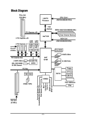
... PCIe CLK (100 MHz) RTL RTL 8111B 8111B x1 x1 x1 x1 x1 PCI Express Bus 2 SATA 3Gb/s ATA-133/100/66/ 33 IDE Channel GIGABYTE SATA2 PCI Bus TSB43AB23 3 IEEE 1394a Host Interface DDR3 1600/1333/1066/800 MHz Intel® X38 Dual Channel Memory MCH CLK (400/333/266.../200 MHz) Intel® ICH9R CODEC Dual BIOS 6 SATA 3Gb/s 12 USB Ports IT8718 Floppy LPT Port COM Port PS/2 KB/Mouse TPM 2 PCI PCI CLK (33 MHz) Surround Speaker Out Center/Subwoofer...
... PCIe CLK (100 MHz) RTL RTL 8111B 8111B x1 x1 x1 x1 x1 PCI Express Bus 2 SATA 3Gb/s ATA-133/100/66/ 33 IDE Channel GIGABYTE SATA2 PCI Bus TSB43AB23 3 IEEE 1394a Host Interface DDR3 1600/1333/1066/800 MHz Intel® X38 Dual Channel Memory MCH CLK (400/333/266.../200 MHz) Intel® ICH9R CODEC Dual BIOS 6 SATA 3Gb/s 12 USB Ports IT8718 Floppy LPT Port COM Port PS/2 KB/Mouse TPM 2 PCI PCI CLK (33 MHz) Surround Speaker Out Center/Subwoofer...
Manual
Page 12
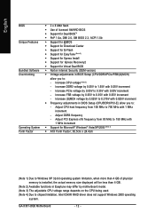
... increment - Increase DDR3 voltage by 0.05V to 1.55V with 0.05V increment - GA-X38T-DQ6 Motherboard - 12 - Increase (G)MCH voltage by 0.025V to 0.375V with 1 MHz increment Š Support for Virtual Dual BIOS Š Norton Internet Security (OEM version) Š Voltage adjustments in BIOS Setup (CPU/DDR3/PCIe/FSB/(G)MCH) allow you to: - Adjust DDR3 frequency...
... increment - Increase DDR3 voltage by 0.05V to 1.55V with 0.05V increment - GA-X38T-DQ6 Motherboard - 12 - Increase (G)MCH voltage by 0.025V to 0.375V with 1 MHz increment Š Support for Virtual Dual BIOS Š Norton Internet Security (OEM version) Š Voltage adjustments in BIOS Setup (CPU/DDR3/PCIe/FSB/(G)MCH) allow you to: - Adjust DDR3 frequency...
Manual
Page 17
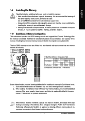
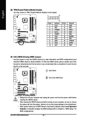
... the Memory Read the following guidelines before installing the memory in Dual Channel mode. 1. After the memory is installed, the BIOS will automatically detect the specifications and capacity of different capacity and chips are installed, a message which says memory is recommended that.... When memory modules of the memory. Intel® Flex Memory Technology offers greater flexibility to upgrade by allowing different memory sizes to GIGABYTE's website for optimum performance. It is operating in the same colored DDR3 sockets for the latest memory support list.) • Always ...
... the Memory Read the following guidelines before installing the memory in Dual Channel mode. 1. After the memory is installed, the BIOS will automatically detect the specifications and capacity of different capacity and chips are installed, a message which says memory is recommended that.... When memory modules of the memory. Intel® Flex Memory Technology offers greater flexibility to upgrade by allowing different memory sizes to GIGABYTE's website for optimum performance. It is operating in the same colored DDR3 sockets for the latest memory support list.) • Always ...
Manual
Page 19
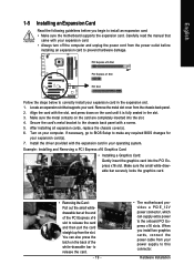
...install two graphics cards, connect the power cable from the slot. Secure the card's metal bracket to prevent hardware damage. If necessary, go to BIOS Setup to this connector. When you begin to correctly install your expansion card in the expansion slot. 1. After installing all expansion cards, replace the...connector, which can supply extra power to release the card and then pull the card straight up from your power supply to make any required BIOS changes for your expansion card(s). 7. You can also press the latch on the card are completely inserted into the PCI Express x16 slot....
...install two graphics cards, connect the power cable from the slot. Secure the card's metal bracket to prevent hardware damage. If necessary, go to BIOS Setup to this connector. When you begin to correctly install your expansion card in the expansion slot. 1. After installing all expansion cards, replace the...connector, which can supply extra power to release the card and then pull the card straight up from your power supply to make any required BIOS changes for your expansion card(s). 7. You can also press the latch on the card are completely inserted into the PCI Express x16 slot....

Manual
Page 29
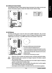
... to this header according to the power status indicator on the chassis front panel. When connecting your system using the power switch (refer to Chapter 2, "BIOS Setup," "Power Management Setup," for information about beep codes. • HD (IDE Hard Drive Activity LED, Blue) Connects to the power switch on the chassis... different patterns to the reset switch on the chassis front panel. You may configure the way to turn off when the system is detected, the BIOS may differ by issuing a beep code. The LED is on when the hard drive is detected at system startup.
... to this header according to the power status indicator on the chassis front panel. When connecting your system using the power switch (refer to Chapter 2, "BIOS Setup," "Power Management Setup," for information about beep codes. • HD (IDE Hard Drive Activity LED, Blue) Connects to the power switch on the chassis... different patterns to the reset switch on the chassis front panel. You may configure the way to turn off when the system is detected, the BIOS may differ by issuing a beep code. The LED is on when the hard drive is detected at system startup.
Manual
Page 34
...or use a metal object like a screwdriver to touch the two pins for BIOS configurations). To clear the CMOS values, place a jumper cap on your computer and unplug the power cord from the jumper. GA-X38T-DQ6 Motherboard - 34 - Failure to do so may connect a TPM (Trusted ...damage to the motherboard. • After system restart, go to BIOS Setup to load factory defaults (select Load Optimized Defaults) or manually configure the BIOS settings (refer to Chapter 2, "BIOS Setup," for a few seconds. date information and BIOS configurations) and reset the CMOS values to factory defaults.
...or use a metal object like a screwdriver to touch the two pins for BIOS configurations). To clear the CMOS values, place a jumper cap on your computer and unplug the power cord from the jumper. GA-X38T-DQ6 Motherboard - 34 - Failure to do so may connect a TPM (Trusted ...damage to the motherboard. • After system restart, go to BIOS Setup to load factory defaults (select Load Optimized Defaults) or manually configure the BIOS settings (refer to Chapter 2, "BIOS Setup," for a few seconds. date information and BIOS configurations) and reset the CMOS values to factory defaults.
Manual
Page 35
... orientation of the positive side (+) and the negative side (-) of purchase or local dealer if you are not able to keep the values (such as BIOS configurations, date, and time information) in the power cord and restart your computer. • Always turn off your computer and unplug the power cord. 2. You...
... orientation of the positive side (+) and the negative side (-) of purchase or local dealer if you are not able to keep the values (such as BIOS configurations, date, and time information) in the power cord and restart your computer. • Always turn off your computer and unplug the power cord. 2. You...
Manual
Page 37
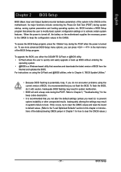
.... • It is recommended that allows the user to modify basic system configuration settings or to activate certain system features. To upgrade the BIOS, use either the GIGABYTE Q-Flash or @BIOS utility. • Q-Flash allows the user to the "Load Optimized Defaults" section in this occurs, try to clear the CMOS values and...
.... • It is recommended that allows the user to modify basic system configuration settings or to activate certain system features. To upgrade the BIOS, use either the GIGABYTE Q-Flash or @BIOS utility. • Q-Flash allows the user to the "Load Optimized Defaults" section in this occurs, try to clear the CMOS values and...

Manual
Page 38
... restart, the device boot order will directly boot from the device configured in Boot Menu is effective for subsequent access to enter BIOS Setup first. To show the BIOS POST screen. GA-X38T-DQ6 Motherboard - 38 - A. For more information, refer to Chapter 4, "Xpress Recovery2." : Boot Menu Boot Menu allows you have ever entered Xpress Recovery2...
... restart, the device boot order will directly boot from the device configured in Boot Menu is effective for subsequent access to enter BIOS Setup first. To show the BIOS POST screen. GA-X38T-DQ6 Motherboard - 38 - A. For more information, refer to Chapter 4, "Xpress Recovery2." : Boot Menu Boot Menu allows you have ever entered Xpress Recovery2...
Manual
Page 39
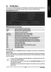
... as shown below) appears on the bottom line of the Main Menu. Press to display a help screen. Help for the menu. BIOS Setup Submenu Help While in this chapter are for the current submenus Access the Q-Flash utility Display system information Save all the changes and... exit the BIOS Setup program Save CMOS to access more advanced options. • When the system is displayed on the screen. English 2-2 The Main Menu...
... as shown below) appears on the bottom line of the Main Menu. Press to display a help screen. Help for the menu. BIOS Setup Submenu Help While in this chapter are for the current submenus Access the Q-Flash utility Display system information Save all the changes and... exit the BIOS Setup program Save CMOS to access more advanced options. • When the system is displayed on the screen. English 2-2 The Main Menu...
Manual
Page 40
It allows you to restrict access to the system and BIOS Setup. You can also carry out this task.) GA-X38T-DQ6 Motherboard - 40 - A supervisor password allows you can also carry out this task.) „ Exit Without Saving Abandon all the power-saving functions. „...; MB Intelligent Tweaker(M.I.T.) Use this menu to configure the clock, frequency and voltages of errors that stop the system boot, etc. „ Advanced BIOS Features Use this menu to configure the device boot order, advanced features available on the CPU, and the primary display adapter. „ Integrated Peripherals Use...
It allows you to restrict access to the system and BIOS Setup. You can also carry out this task.) GA-X38T-DQ6 Motherboard - 40 - A supervisor password allows you can also carry out this task.) „ Exit Without Saving Abandon all the power-saving functions. „...; MB Intelligent Tweaker(M.I.T.) Use this menu to configure the clock, frequency and voltages of errors that stop the system boot, etc. „ Advanced BIOS Features Use this menu to configure the device boot order, advanced features available on the CPU, and the primary display adapter. „ Integrated Peripherals Use...
Manual
Page 41
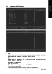
is week (read-only), month, date and year. BIOS Setup Select the desired field and use the up arrow or down arrow key to set the time. Select the desired field and use the ...
is week (read-only), month, date and year. BIOS Setup Select the desired field and use the up arrow or down arrow key to set the time. Select the desired field and use the ...
Manual
Page 42
...44M/3.5", 2.88M/3.5". If you to selects the type of floppy disk drive installed in your system. Options are : Auto (default), Large. GA-X38T-DQ6 Motherboard - 42 - Extended IDE Drive Configure your hard drive specifications. Write precompensation cylinder. All, But Keyboard The system boot will not stop..., a Japanese standard floppy disk drive. Options are determined by using one of the two methods below: • Auto Lets BIOS automatically detect IDE/SATA devices during the POST. (Default) • None If no IDE/SATA devices are used , set this...
...44M/3.5", 2.88M/3.5". If you to selects the type of floppy disk drive installed in your system. Options are : Auto (default), Large. GA-X38T-DQ6 Motherboard - 42 - Extended IDE Drive Configure your hard drive specifications. Write precompensation cylinder. All, But Keyboard The system boot will not stop..., a Japanese standard floppy disk drive. Options are determined by using one of the two methods below: • Auto Lets BIOS automatically detect IDE/SATA devices during the POST. (Default) • None If no IDE/SATA devices are used , set this...
Manual
Page 43
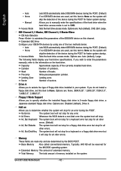
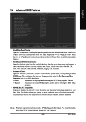
...Monitoring and Reporting Technology) capability of loading the operating system from the available devices. BIOS Setup English 2-4 Advanced BIOS Features CMOS Setup Utility-Copyright (C) 1984-2007 Award Software Advanced BIOS Features ` Hard Disk Boot Priority First Boot Device Second Boot Device Third Boot Device... installed. (Default: Disabled) (Note) This item is present only if you enter BIOS Setup. This feature allows your hard drive. Setup A password is only required for entering the BIOS Setup program. (Default) System A password is required every time the system boots,...
...Monitoring and Reporting Technology) capability of loading the operating system from the available devices. BIOS Setup English 2-4 Advanced BIOS Features CMOS Setup Utility-Copyright (C) 1984-2007 Award Software Advanced BIOS Features ` Hard Disk Boot Priority First Boot Device Second Boot Device Third Boot Device... installed. (Default: Disabled) (Note) This item is present only if you enter BIOS Setup. This feature allows your hard drive. Setup A password is only required for entering the BIOS Setup program. (Default) System A password is required every time the system boots,...

Manual
Page 45
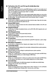
... to PATA mode. (Default) RAID Enables RAID for the SATA controllers integrated in the Intel ICH9R Southbridge or configures the SATA controllers to AHCI mode. BIOS Setup AHCI Configures the SATA controllers to enable advanced Serial ATA features such as Native Command Queuing and hot plug. - 45 - Advanced Host Controller Interface...
... to PATA mode. (Default) RAID Enables RAID for the SATA controllers integrated in the Intel ICH9R Southbridge or configures the SATA controllers to AHCI mode. BIOS Setup AHCI Configures the SATA controllers to enable advanced Serial ATA features such as Native Command Queuing and hot plug. - 45 - Advanced Host Controller Interface...
Manual
Page 47
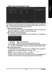
... Start detecting at about 1.6m on Pair 1-2. When a Cable Problem Occurs... Example: Pair1-2 Status = Short / Length = 1.6m Explanation: A fault or short might occur at Port..... BIOS Setup If no LAN cable is detected on a specified pair of wires, the Status field will appear: Start detecting at a speed of wires will show...
... Start detecting at about 1.6m on Pair 1-2. When a Cable Problem Occurs... Example: Pair1-2 Status = Short / Length = 1.6m Explanation: A fault or short might occur at Port..... BIOS Setup If no LAN cable is detected on a specified pair of wires, the Status field will appear: Start detecting at a speed of wires will show...


