Manual
Page 4
... 1-4-2 Installing a Memory 17 1-5 Installing an Expansion Card 18 1-6 Setup of ATI CrossFireX™/NVIDIA SLI Configuration 19 1-7 Installing the SATA Bracket 20 1-8 Back Panel Connectors 21 1-9 Onboard LEDs and Buttons 23 1-10 Internal Connectors 25 Chapter 2 BIOS Setup 35 2-1 Startup Screen 36 2-2 The Main Menu 37 2-3 MB Intelligent Tweaker(M.I.T 39 2-4 Standard CMOS Features 47 2-5 Advanced BIOS Features 49 2-6 Integrated Peripherals 51 2-7 Power Management Setup 55 2-8 PC Health Status 57 2-9 Load Fail-Safe Defaults 59 2-10 Load Optimized Defaults 59 2-11 Set...
... 1-4-2 Installing a Memory 17 1-5 Installing an Expansion Card 18 1-6 Setup of ATI CrossFireX™/NVIDIA SLI Configuration 19 1-7 Installing the SATA Bracket 20 1-8 Back Panel Connectors 21 1-9 Onboard LEDs and Buttons 23 1-10 Internal Connectors 25 Chapter 2 BIOS Setup 35 2-1 Startup Screen 36 2-2 The Main Menu 37 2-3 MB Intelligent Tweaker(M.I.T 39 2-4 Standard CMOS Features 47 2-5 Advanced BIOS Features 49 2-6 Integrated Peripherals 51 2-7 Power Management Setup 55 2-8 PC Health Status 57 2-9 Load Fail-Safe Defaults 59 2-10 Load Optimized Defaults 59 2-11 Set...
Manual
Page 19
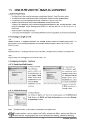
... CrossFireX technologies currently support Windows 7 and Vista operating systems - Step 3: Plug the display cable into the graphics card on the PCIEX16_1 and PCIEX16_2 slots. ) Step 2: Insert the CrossFire (Note )/SLI bridge connectors in the operating system, go to the manual of the two/three cards. To Enable SLI Function For 2-Way/3-Way SLI: After installing the graphics card driver in the operating system, go to the Catalyst Control Center. Procedure and driver screen...
... CrossFireX technologies currently support Windows 7 and Vista operating systems - Step 3: Plug the display cable into the graphics card on the PCIEX16_1 and PCIEX16_2 slots. ) Step 2: Insert the CrossFire (Note )/SLI bridge connectors in the operating system, go to the manual of the two/three cards. To Enable SLI Function For 2-Way/3-Way SLI: After installing the graphics card driver in the operating system, go to the Catalyst Control Center. Procedure and driver screen...
Manual
Page 24
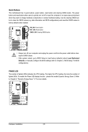
...: Power button RST_SW: Reset button CMOS_SW: Clearing CMOS button • Always turn on/off your computer and unplug the power cord from the power outlet before clearing the CMOS values. • After system restart, go to BIOS Setup to load factory defaults (select Load Optimized Defaults) or manually configure the BIOS settings (refer to Chapter 2, "BIOS Setup," for more the number of lighted LEDs indicates the CPU loading. Hardware Installation - 24 - PHASE LED The number of lighted LEDs. To enable the Phase LED display function...
...: Power button RST_SW: Reset button CMOS_SW: Clearing CMOS button • Always turn on/off your computer and unplug the power cord from the power outlet before clearing the CMOS values. • After system restart, go to BIOS Setup to load factory defaults (select Load Optimized Defaults) or manually configure the BIOS settings (refer to Chapter 2, "BIOS Setup," for more the number of lighted LEDs indicates the CPU loading. Hardware Installation - 24 - PHASE LED The number of lighted LEDs. To enable the Phase LED display function...
Manual
Page 36
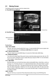
...to access the Q-Flash utility in Boot Menu is effective for subsequent access to access the Q-Flash utility directly without entering BIOS Setup. A. Motherboard Model BIOS Version P67A-UD7 F3a . . . . : BIOS Setup : XpressRecovery2 : Boot Menu : Qflash 10/28/2010-P67-7A89UG04C-00 Function Keys Function Keys: : POST SCREEN Press the key to show the BIOS POST screen at system startup, refer to the instructions on the Full Screen LOGO Show item on BIOS Setup settings. In Boot Menu, use the up hard drive data using the driver disk, the key can access Boot Menu again to change the...
...to access the Q-Flash utility in Boot Menu is effective for subsequent access to access the Q-Flash utility directly without entering BIOS Setup. A. Motherboard Model BIOS Version P67A-UD7 F3a . . . . : BIOS Setup : XpressRecovery2 : Boot Menu : Qflash 10/28/2010-P67-7A89UG04C-00 Function Keys Function Keys: : POST SCREEN Press the key to show the BIOS POST screen at system startup, refer to the instructions on the Full Screen LOGO Show item on BIOS Setup settings. In Boot Menu, use the up hard drive data using the driver disk, the key can access Boot Menu again to change the...

Manual
Page 38
... the changes made in BIOS Setup. Set User Password Change, set , or disable password. The Functions of errors that stop the system boot, etc. Advanced BIOS Features Use this menu to configure the device boot order, advanced features available on the CPU, and the primary display adapter. Integrated Peripherals Use this menu to configure all peripheral devices, such as SATA, USB, integrated audio, and integrated LAN, etc. Power Management Setup Use this task.) BIOS Setup - 38 - A supervisor password allows...
... the changes made in BIOS Setup. Set User Password Change, set , or disable password. The Functions of errors that stop the system boot, etc. Advanced BIOS Features Use this menu to configure the device boot order, advanced features available on the CPU, and the primary display adapter. Integrated Peripherals Use this menu to configure all peripheral devices, such as SATA, USB, integrated audio, and integrated LAN, etc. Power Management Setup Use this task.) BIOS Setup - 38 - A supervisor password allows...
Manual
Page 41
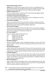
... in BIOS setup. (Default: Disabled) Intel(R) Turbo Boost Tech. (Note) Allows you install a CPU that supports this item to Disabled if you to enable multi-threading technology when using an Intel CPU that supports this setting. (Default: Auto) CPU Thermal Monitor (Note) Enables or disables Intel CPU Thermal Monitor function, a CPU overheating protection function. Auto sets the current limit according to the CPU specifications. (Default: Auto) CPU Cores Enabled (Note) Allows you to determine whether to set a power limit for CPU Turbo mode. This feature only works...
... in BIOS setup. (Default: Disabled) Intel(R) Turbo Boost Tech. (Note) Allows you install a CPU that supports this item to Disabled if you to enable multi-threading technology when using an Intel CPU that supports this setting. (Default: Auto) CPU Thermal Monitor (Note) Enables or disables Intel CPU Thermal Monitor function, a CPU overheating protection function. Auto sets the current limit according to the CPU specifications. (Default: Auto) CPU Cores Enabled (Note) Allows you to determine whether to set a power limit for CPU Turbo mode. This feature only works...

Manual
Page 45
... : Auto (default), 1~255. Advanced Voltage Settings CMOS Setup Utility-Copyright (C) 1984-2010 Award Software Advanced Voltage Settings ****** Mother Board Voltage Control ****** Voltage Types Normal Current >>> CPU Load-Line Calibration [Auto] CPU Vcore 1.275V [Auto] + Dynamic Vcore(DVID) +0.000V Auto QPI/Vtt Voltage 1.050V [Auto] System Agent Voltage 0.920V [Auto] >>> MCH/ICH PCH Core 1.050V [Auto] CPU PLL 1.800V [Auto] >>> DRAM DRAM Voltage 1.500V [Auto] DRAM VRef. 0.750V [Auto] DRAM Termination 0.750V [Auto...
... : Auto (default), 1~255. Advanced Voltage Settings CMOS Setup Utility-Copyright (C) 1984-2010 Award Software Advanced Voltage Settings ****** Mother Board Voltage Control ****** Voltage Types Normal Current >>> CPU Load-Line Calibration [Auto] CPU Vcore 1.275V [Auto] + Dynamic Vcore(DVID) +0.000V Auto QPI/Vtt Voltage 1.050V [Auto] System Agent Voltage 0.920V [Auto] >>> MCH/ICH PCH Core 1.050V [Auto] CPU PLL 1.800V [Auto] >>> DRAM DRAM Voltage 1.500V [Auto] DRAM VRef. 0.750V [Auto] DRAM Termination 0.750V [Auto...
Manual
Page 46
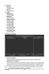
... present only when you install a CPU that supports this feature. Ch-B Data VRef. With virtualization, one computer system can function as multiple virtual systems. (Default: Enabled) (Note) This item is Auto. DRAM VRef. Ch-A Data VRef. The default is Auto. The default is Auto. Miscellaneous Settings CMOS Setup Utility-Copyright (C) 1984-2010 Award Software Miscellaneous Settings Isochronous Support Virtualization Technology (Note) [Enabled] [Enabled] Item Help Menu Level Move Enter: Select F5: Previous Values +/-/PU...
... present only when you install a CPU that supports this feature. Ch-B Data VRef. With virtualization, one computer system can function as multiple virtual systems. (Default: Enabled) (Note) This item is Auto. DRAM VRef. Ch-A Data VRef. The default is Auto. The default is Auto. Miscellaneous Settings CMOS Setup Utility-Copyright (C) 1984-2010 Award Software Miscellaneous Settings Isochronous Support Virtualization Technology (Note) [Enabled] [Enabled] Item Help Menu Level Move Enter: Select F5: Previous Values +/-/PU...

Manual
Page 52
.../LAN2 Enables or disables the onboard LAN function. (Default: Enabled) If you wish to install a 3rd party add-in audio card instead of using the onboard LAN, set this item to the fault or short. SMART LAN1/LAN2 (LAN Cable Diagnostic Function) CMOS Setup Utility-Copyright (C) 1984-2010 Award Software SMART LAN Start detecting at Port..... Refer to AHCI mode. SATA Port0-3 Native Mode (Intel P67 Chipset) Specifies the operating mode of the attached LAN cable. AHCI Configures the SATA controllers to the following information for diagnosing your LAN cable: BIOS Setup...
.../LAN2 Enables or disables the onboard LAN function. (Default: Enabled) If you wish to install a 3rd party add-in audio card instead of using the onboard LAN, set this item to the fault or short. SMART LAN1/LAN2 (LAN Cable Diagnostic Function) CMOS Setup Utility-Copyright (C) 1984-2010 Award Software SMART LAN Start detecting at Port..... Refer to AHCI mode. SATA Port0-3 Native Mode (Intel P67 Chipset) Specifies the operating mode of the attached LAN cable. AHCI Configures the SATA controllers to the following information for diagnosing your LAN cable: BIOS Setup...

Manual
Page 53
...: Start detecting at Port..... IDE Configures the SATA controller to IDE mode. (Default) AHCI Configures the SATA controller to AHCI mode. BIOS Setup When LAN Cable Is Functioning Normally... If no LAN cable is detected on Part 1-2. Note: Part 4-5 and Part 7-8 are not used in the Marvell 88SE9128 chip. (Default: Enabled) GSATA3 Ctrl Mode (Marvell 88SE9128 Chip, GSATA3_6 and GSATA3_7 Connectors) Allows you to decide whether to activate the boot ROM integrated with the onboard LAN chip. (Default: Disabled) Onboard USB3.0 Controller (1st Renesas D720200 USB 3.0 Controller, 5 USB...
...: Start detecting at Port..... IDE Configures the SATA controller to IDE mode. (Default) AHCI Configures the SATA controller to AHCI mode. BIOS Setup When LAN Cable Is Functioning Normally... If no LAN cable is detected on Part 1-2. Note: Part 4-5 and Part 7-8 are not used in the Marvell 88SE9128 chip. (Default: Enabled) GSATA3 Ctrl Mode (Marvell 88SE9128 Chip, GSATA3_6 and GSATA3_7 Connectors) Allows you to decide whether to activate the boot ROM integrated with the onboard LAN chip. (Default: Disabled) Onboard USB3.0 Controller (1st Renesas D720200 USB 3.0 Controller, 5 USB...

Manual
Page 54
... the storage driver to AHCI mode. eSATA3 Controller (Marvell 88SE9128 Chip, eSATA Connectors on the Back Panel) Enables or disables the SATA controller integrated in the system BIOS, even if it's not the latest one. Lets the BIOS automatically update the firmware to the latest version. (Default) Forces the BIOS to Chapter 5, "Configuring SATA Hard Drive(s)," for the Marvell 88SE9128 SATA controller. BIOS Setup - 54 - Fw Mode Enables RAID. (Default) Auto Lets the BIOS configure this setting depending on the hard drives connected. Refer to flash the firmware with...
... the storage driver to AHCI mode. eSATA3 Controller (Marvell 88SE9128 Chip, eSATA Connectors on the Back Panel) Enables or disables the SATA controller integrated in the system BIOS, even if it's not the latest one. Lets the BIOS automatically update the firmware to the latest version. (Default) Forces the BIOS to Chapter 5, "Configuring SATA Hard Drive(s)," for the Marvell 88SE9128 SATA controller. BIOS Setup - 54 - Fw Mode Enables RAID. (Default) Auto Lets the BIOS configure this setting depending on the hard drives connected. Refer to flash the firmware with...

Manual
Page 55
... a wake-up signal from a PCI or PCIe device. In S1 sleep state, the system appears suspended and stays in MS-DOS mode using the power button. In S3 sleep state, the system appears to enter the ACPI S1 (Power on Windows 7/Vista operating system only. - 55 - PME Event Wake Up Allows the system to be turned off instantly. (Default) Delay 4 Sec. 2-7 Power Management Setup CMOS Setup Utility-Copyright (C) 1984-2010 Award Software Power Management Setup ACPI Suspend Type ACPI LED Control...
... a wake-up signal from a PCI or PCIe device. In S1 sleep state, the system appears suspended and stays in MS-DOS mode using the power button. In S3 sleep state, the system appears to enter the ACPI S1 (Power on Windows 7/Vista operating system only. - 55 - PME Event Wake Up Allows the system to be turned off instantly. (Default) Delay 4 Sec. 2-7 Power Management Setup CMOS Setup Utility-Copyright (C) 1984-2010 Award Software Power Management Setup ACPI Suspend Type ACPI LED Control...

Manual
Page 58
... fan speed. This item is configurable only when CPU Smart FAN Control is set to the CPU temperature. Options are : Disabled (default), 60oC/140oF, 70oC/158oF, 80oC/176oF, 90oC/194oF. Auto Lets the BIOS automatically detect the type of CPU fan installed and sets the optimal CPU fan control mode. (Default) Voltage Sets Voltage mode for a 3-pin CPU fan or a 4-pin CPU fan. BIOS Setup - 58 - Options are : 0.75 PWM value /oC ~ 2.50 PWM value /oC. This item is configurable only when CPU Smart FAN Control is set to emit warning sound if the CPU/power/system fan...
... fan speed. This item is configurable only when CPU Smart FAN Control is set to the CPU temperature. Options are : Disabled (default), 60oC/140oF, 70oC/158oF, 80oC/176oF, 90oC/194oF. Auto Lets the BIOS automatically detect the type of CPU fan installed and sets the optimal CPU fan control mode. (Default) Voltage Sets Voltage mode for a 3-pin CPU fan or a 4-pin CPU fan. BIOS Setup - 58 - Options are : 0.75 PWM value /oC ~ 2.50 PWM value /oC. This item is configurable only when CPU Smart FAN Control is set to emit warning sound if the CPU/power/system fan...
Manual
Page 71
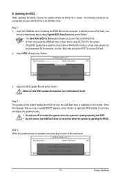
... the USB flash drive containing the BIOS file into the computer. Q-Flash Utility v2.17 Flash Type/Size MXIC 25L3206E 4M Keep0 DfilMe(Is)DfaotuandEnable HDD 1-0 Loa d CMO S Default Enable Update BIOS from the USB flash drive is saved to a hard drive in RAID/AHCI mode or a hard drive attached to an independent SATA controller, use the up or down arrow key to select Update BIOS from Drive Please SparevsesBaInOySketoy Dtoricvoentinue Enter : Run hi:Move ESC:Reset F10:Power Off - 71 - Step 2: The process of Q-Flash, use the key...
... the USB flash drive containing the BIOS file into the computer. Q-Flash Utility v2.17 Flash Type/Size MXIC 25L3206E 4M Keep0 DfilMe(Is)DfaotuandEnable HDD 1-0 Loa d CMO S Default Enable Update BIOS from the USB flash drive is saved to a hard drive in RAID/AHCI mode or a hard drive attached to an independent SATA controller, use the up or down arrow key to select Update BIOS from Drive Please SparevsesBaInOySketoy Dtoricvoentinue Enter : Run hi:Move ESC:Reset F10:Power Off - 71 - Step 2: The process of Q-Flash, use the key...
Manual
Page 83
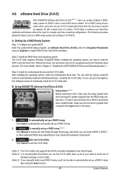
For a RAID 0 array that already exists, users also can go to the Application Software screen to enable RAID for RAID 0 when a new SATA drive is added. Step 2: Install the RAID driver and operating system The X.H.D utility supports Windows 7/Vista/XP. A. Setting Up a RAID-Ready System Step 1: Configure the system BIOS Enter the system BIOS Setup program, set eXtreme Hard Drive (X.H.D) under the Integrated Peripherals menu to Enabled to individually install the X.H.D utility later. You can click the Xpress Install All button to...
For a RAID 0 array that already exists, users also can go to the Application Software screen to enable RAID for RAID 0 when a new SATA drive is added. Step 2: Install the RAID driver and operating system The X.H.D utility supports Windows 7/Vista/XP. A. Setting Up a RAID-Ready System Step 1: Configure the system BIOS Enter the system BIOS Setup program, set eXtreme Hard Drive (X.H.D) under the Integrated Peripherals menu to Enabled to individually install the X.H.D utility later. You can click the Xpress Install All button to...

Manual
Page 95
...AHCI Set eSATA3 Controller to Enabled Set eSATA3 Ctrl Mode to IDE or AHCI CMOS Setup Utility-Copyright (C) 1984-2010 Award Software Integrated Peripherals } SMART LAN1 } SMART LAN2 Onboard LAN1 Boot ROM Onboard LAN2 Boot ROM Onboard USB 3.0 Controller USB3.0 Turbo Onboard USB 3.0 Controller2 GSATA3 Controller GSATA3 Ctrl Mode GSATA3 Transaction Mode GSATA3 RAID Configuration eSATA3 Controller eSATA3 Ctrl Mode eSATA3 Transaction Mode eSATA3 RAID Configuration SATA3 Firmware Selection [Press Enter] [Press Enter] [Disabled] [Disabled [Enabled] [Disabled...
...AHCI Set eSATA3 Controller to Enabled Set eSATA3 Ctrl Mode to IDE or AHCI CMOS Setup Utility-Copyright (C) 1984-2010 Award Software Integrated Peripherals } SMART LAN1 } SMART LAN2 Onboard LAN1 Boot ROM Onboard LAN2 Boot ROM Onboard USB 3.0 Controller USB3.0 Turbo Onboard USB 3.0 Controller2 GSATA3 Controller GSATA3 Ctrl Mode GSATA3 Transaction Mode GSATA3 RAID Configuration eSATA3 Controller eSATA3 Ctrl Mode eSATA3 Transaction Mode eSATA3 RAID Configuration SATA3 Firmware Selection [Press Enter] [Press Enter] [Disabled] [Disabled [Enabled] [Disabled...
Manual
Page 100
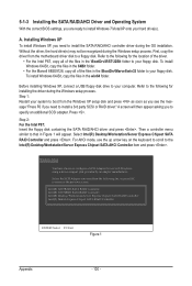
... Express Chipset SATA AHCI Controller item and press . To install Windows 64-Bit, copy the files in the \BootDrv\iRST\32Bit folder to the previous screen. Then a controller menu similar to install Windows 7/Vista/XP onto your floppy disk. Select the SCSI Adapter you need to specify an additional SCSI adapter. Before installing Windows XP, connect a USB floppy disk drive to a floppy disk. First, copy the driver from the motherboard driver disk to your system to boot from the Windows XP setup disk...
... Express Chipset SATA AHCI Controller item and press . To install Windows 64-Bit, copy the files in the \BootDrv\iRST\32Bit folder to the previous screen. Then a controller menu similar to install Windows 7/Vista/XP onto your floppy disk. Select the SCSI Adapter you need to specify an additional SCSI adapter. Before installing Windows XP, connect a USB floppy disk drive to a floppy disk. First, copy the driver from the motherboard driver disk to your system to boot from the Windows XP setup disk...
Manual
Page 101
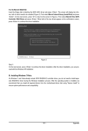
... with Windows, using "Xpress Install" to the previous screen. Then select Marvell 91xx SATA Controller 32bit Driver and press . After the driver installation, you do not need to configure a SCSI Adapter for use with the Windows XP installation. After the operating system is installed, we recommend that you want from the motherboard driver disk using a device support disk provided by an adapter manufacturer. For the Marvell 88SE9128: Insert the floppy disk containing the SATA AHCI driver...
... with Windows, using "Xpress Install" to the previous screen. Then select Marvell 91xx SATA Controller 32bit Driver and press . After the driver installation, you do not need to configure a SCSI Adapter for use with the Windows XP installation. After the operating system is installed, we recommend that you want from the motherboard driver disk using a device support disk provided by an adapter manufacturer. For the Marvell 88SE9128: Insert the floppy disk containing the SATA AHCI driver...
Manual
Page 114
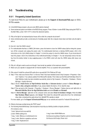
...: CMOS setting error 1 long, 9 short: BIOS ROM error 1 long, 1 short: Memory or motherboard error Continuous long beeps: Graphics card not inserted properly 1 long, 2 short: Monitor or graphics card error Continuous short beeps: Power error 1 long, 3 short: Keyboard error Appendix - 114 - Q: In the BIOS Setup program, why are hidden in My Computer > Properties > Gen- In the Main Menu, press + to install. If your board doesn't have a CMOS_SW button, press this button to clear the CMOS values (before doing this jumper, refer to the instructions on the motherboard battery in Device...
...: CMOS setting error 1 long, 9 short: BIOS ROM error 1 long, 1 short: Memory or motherboard error Continuous long beeps: Graphics card not inserted properly 1 long, 2 short: Monitor or graphics card error Continuous short beeps: Power error 1 long, 3 short: Keyboard error Appendix - 114 - Q: In the BIOS Setup program, why are hidden in My Computer > Properties > Gen- In the Main Menu, press + to install. If your board doesn't have a CMOS_SW button, press this button to clear the CMOS values (before doing this jumper, refer to the instructions on the motherboard battery in Device...

Manual
Page 119
... IDE devices: HDD, LS120, ZIP, CDROM... If no errors occur or F1 key is supported - Assign IRQs to continue: 2. APM initialization Clear noise of the memory 1. Appendix Initialize Init_Onbaord_AUDIO Okay to "AUTO" 1. Auto assign ports to onboard COM ports if the corresponding item in Setup is set to enter Setup utility; Recover the text fond used by EPA logo (not for Trend Anti-Virus code - 119 - i.e. Call chipset power management hook 2. Initialize floppy controller 2. Set...
... IDE devices: HDD, LS120, ZIP, CDROM... If no errors occur or F1 key is supported - Assign IRQs to continue: 2. APM initialization Clear noise of the memory 1. Appendix Initialize Init_Onbaord_AUDIO Okay to "AUTO" 1. Auto assign ports to onboard COM ports if the corresponding item in Setup is set to enter Setup utility; Recover the text fond used by EPA logo (not for Trend Anti-Virus code - 119 - i.e. Call chipset power management hook 2. Initialize floppy controller 2. Set...


