Manual
Page 1
GA-P67A-UD7 LGA1155 socket motherboard for Intel® Core™ i7 processors/ Intel® Core™ i5 processors/ Intel® Core™ i3 processors/ Intel® Pentium® processors/ Intel® Celeron® processors User's Manual Rev. 1001 12ME-P67AUD7-1001R
GA-P67A-UD7 LGA1155 socket motherboard for Intel® Core™ i7 processors/ Intel® Core™ i5 processors/ Intel® Core™ i3 processors/ Intel® Pentium® processors/ Intel® Celeron® processors User's Manual Rev. 1001 12ME-P67AUD7-1001R
Manual
Page 2
Motherboard GA-P67A-UD7 Nov. 8, 2010 Motherboard GA-P67A-UD7 Nov. 8, 2010
Motherboard GA-P67A-UD7 Nov. 8, 2010 Motherboard GA-P67A-UD7 Nov. 8, 2010

Manual
Page 3
... and is 1.0. For product-related information, check on our website at: http://www.gigabyte.com Identifying Your Motherboard Revision The revision number on your motherboard revision before updating motherboard BIOS, drivers, or when looking for technical information. For example, "REV: 1.0"... means the revision of the motherboard is the property of GIGABYTE. Check your motherboard looks like this manual is protected by GIGABYTE without GIGABYTE's prior written permission. Disclaimer Information in the use of the product, read the...
... and is 1.0. For product-related information, check on our website at: http://www.gigabyte.com Identifying Your Motherboard Revision The revision number on your motherboard revision before updating motherboard BIOS, drivers, or when looking for technical information. For example, "REV: 1.0"... means the revision of the motherboard is the property of GIGABYTE. Check your motherboard looks like this manual is protected by GIGABYTE without GIGABYTE's prior written permission. Disclaimer Information in the use of the product, read the...
Manual
Page 4
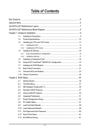
Table of Contents Box Contents...6 Optional Items...6 GA-P67A-UD7 Motherboard Layout 7 GA-P67A-UD7 Motherboard Block Diagram 8 Chapter 1 Hardware Installation 9 1-1 Installation Precautions 9 1-2 Product Specifications 10 1-3 Installing the CPU and CPU Cooler 13 1-3-1 Installing the CPU 13 1-3-2 Installing the CPU Cooler ...
Table of Contents Box Contents...6 Optional Items...6 GA-P67A-UD7 Motherboard Layout 7 GA-P67A-UD7 Motherboard Block Diagram 8 Chapter 1 Hardware Installation 9 1-1 Installation Precautions 9 1-2 Product Specifications 10 1-3 Installing the CPU and CPU Cooler 13 1-3-1 Installing the CPU 13 1-3-2 Installing the CPU Cooler ...
Manual
Page 6
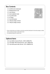
Box Contents GA-P67A-UD7 motherboard Motherboard driver disk User's Manual Quick Installation Guide Four SATA cables I/O Shield One SATA bracket 2-Way SLI bridge connector 3-Way SLI bridge connector • The box contents above are subject to change without notice. • The motherboard image is for reference only and the actual items shall depend on the product...
Box Contents GA-P67A-UD7 motherboard Motherboard driver disk User's Manual Quick Installation Guide Four SATA cables I/O Shield One SATA bracket 2-Way SLI bridge connector 3-Way SLI bridge connector • The box contents above are subject to change without notice. • The motherboard image is for reference only and the actual items shall depend on the product...
Manual
Page 7
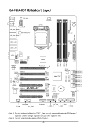
GA-P67A-UD7 Motherboard Layout KB_USB3 SYS_FAN1 R_SPDIF ATX_12V_2X USB_1394_ESATA_2 Marvell 88SE9128 USB_1394_ESATA_1 LGA1155 CPU_FAN PHASE LED PW_SW RST_SW PWR_FAN USB30_LAN2 CMOS_SW USB30_LAN1 VLI VL810 F_AUDIO AUDIO Renesas GD2 GD1 PCIEX1_1 (Note 1) D720200 Renesas D720200 NF200 PCIEX16_1 SPDIF_O Realtek PCIEX8_1 RTL8111E Realtek PCIEX16_2 RTL8111E PCI1 CODEC T.I. TSB43AB23 PCIEX8_2 GA-P67A-UD7 iTE IT8892 Bridge PCI2 VLI VL810 MD2...
GA-P67A-UD7 Motherboard Layout KB_USB3 SYS_FAN1 R_SPDIF ATX_12V_2X USB_1394_ESATA_2 Marvell 88SE9128 USB_1394_ESATA_1 LGA1155 CPU_FAN PHASE LED PW_SW RST_SW PWR_FAN USB30_LAN2 CMOS_SW USB30_LAN1 VLI VL810 F_AUDIO AUDIO Renesas GD2 GD1 PCIEX1_1 (Note 1) D720200 Renesas D720200 NF200 PCIEX16_1 SPDIF_O Realtek PCIEX8_1 RTL8111E Realtek PCIEX16_2 RTL8111E PCI1 CODEC T.I. TSB43AB23 PCIEX8_2 GA-P67A-UD7 iTE IT8892 Bridge PCI2 VLI VL810 MD2...
Manual
Page 8
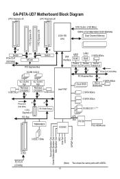
GA-P67A-UD7 Motherboard Block Diagram 2 PCI Express x8 2 PCI Express x8 LGA1155 CPU CPU CLK+/- (100 MHz) DDR3 2133/1866/1600/1333/1066 MHz Dual Channel Memory 1 PCI ...
GA-P67A-UD7 Motherboard Block Diagram 2 PCI Express x8 2 PCI Express x8 LGA1155 CPU CPU CLK+/- (100 MHz) DDR3 2133/1866/1600/1333/1066 MHz Dual Channel Memory 1 PCI ...
Manual
Page 9
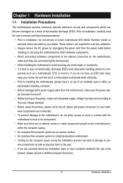
... on top of an antistatic pad or within an electrostatic shielding container. • Before unplugging the power supply cable from the motherboard, make sure the power supply has been turned off. • Before turning on the computer power during the installation process can become... using the product, please verify that all cables and power connectors of your hardware components are connected. • To prevent damage to the motherboard, do not have an ESD wrist strap, keep your dealer. Hardware Installation These stickers are uncertain about any metal leads or connectors. •...
... on top of an antistatic pad or within an electrostatic shielding container. • Before unplugging the power supply cable from the motherboard, make sure the power supply has been turned off. • Before turning on the computer power during the installation process can become... using the product, please verify that all cables and power connectors of your hardware components are connected. • To prevent damage to the motherboard, do not have an ESD wrist strap, keep your dealer. Hardware Installation These stickers are uncertain about any metal leads or connectors. •...

Manual
Page 12
... ŠŠ Support for Xpress Install ŠŠ Support for Xpress Recovery2 ŠŠ Support for EasyTune * Available functions in EasyTune may differ by motherboard model. ŠŠ Support for Dynamic Energy Saver™ 2 ŠŠ Support for Smart 6™ ŠŠ Support for Auto Green Š... ŠŠ Support for Microsoft® Windows® 7/Vista/XP Form Factor ŠŠ ATX Form Factor; 30.5cm x 24.4cm * GIGABYTE reserves the right to make any changes to the product specifications and product-related information without prior notice.
... ŠŠ Support for Xpress Install ŠŠ Support for Xpress Recovery2 ŠŠ Support for EasyTune * Available functions in EasyTune may differ by motherboard model. ŠŠ Support for Dynamic Energy Saver™ 2 ŠŠ Support for Smart 6™ ŠŠ Support for Auto Green Š... ŠŠ Support for Microsoft® Windows® 7/Vista/XP Form Factor ŠŠ ATX Form Factor; 30.5cm x 24.4cm * GIGABYTE reserves the right to make any changes to the product specifications and product-related information without prior notice.
Manual
Page 13
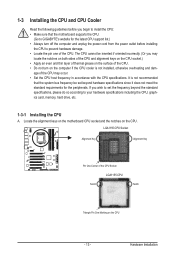
It is not recommended that the motherboard supports the CPU. (Go to GIGABYTE's website for the peripherals. LGA1155 CPU Socket Alignment Key Alignment Key Pin One Corner of the CPU Socket LGA1155 CPU Notch Notch Triangle Pin One ... if oriented incorrectly. (Or you may occur. • Set the CPU host frequency in accordance with the CPU specifications. Locate the alignment keys on the motherboard CPU socket and the notches on the CPU - 13 - Hardware Installation The CPU cannot be set the frequency beyond hardware specifications since it does not...
It is not recommended that the motherboard supports the CPU. (Go to GIGABYTE's website for the peripherals. LGA1155 CPU Socket Alignment Key Alignment Key Pin One Corner of the CPU Socket LGA1155 CPU Notch Notch Triangle Pin One ... if oriented incorrectly. (Or you may occur. • Set the CPU host frequency in accordance with the CPU specifications. Locate the alignment keys on the motherboard CPU socket and the notches on the CPU - 13 - Hardware Installation The CPU cannot be set the frequency beyond hardware specifications since it does not...

Manual
Page 14
....) Step 3: Hold the CPU with the pin one hand to hold the socket lever and use the other to correctly install the CPU into the motherboard CPU socket. Then completely lift the CPU socket lever and the metal load plate will be lifted as shown. When replacing the load plate, make...
....) Step 3: Hold the CPU with the pin one hand to hold the socket lever and use the other to correctly install the CPU into the motherboard CPU socket. Then completely lift the CPU socket lever and the metal load plate will be lifted as shown. When replacing the load plate, make...

Manual
Page 15
..., on the contrary, is to install.) Step 3: Place the cooler atop the CPU, aligning the four push pins through the pin holes on the motherboard. Step 2: Before installing the cooler, note the direction of the arrow sign on the male push pin. (Turning the push pin along the direction ... that the Male and Female push pins are joined closely. (Refer to your CPU cooler installation manual for instructions on the surface of the motherboard. Hardware Installation Use extreme care when removing the CPU cooler because the thermal grease/tape between the CPU cooler and CPU may damage the CPU...
..., on the contrary, is to install.) Step 3: Place the cooler atop the CPU, aligning the four push pins through the pin holes on the motherboard. Step 2: Before installing the cooler, note the direction of the arrow sign on the male push pin. (Turning the push pin along the direction ... that the Male and Female push pins are joined closely. (Refer to your CPU cooler installation manual for instructions on the surface of the motherboard. Hardware Installation Use extreme care when removing the CPU cooler because the thermal grease/tape between the CPU cooler and CPU may damage the CPU...

Manual
Page 16
... the power outlet before installing the memory in only one DDR3 memory module is recommended that the motherboard supports the memory. Enabling Dual Channel memory mode will automatically detect the specifications and capacity of the...DDR3 memory sockets are unable to insert the memory, switch the direction. 1-4-1 Dual Channel Memory Configuration This motherboard provides four DDR3 memory sockets and supports Dual Channel Technology. DS/SS Four Modules DS/SS DS/SS...• Make sure that memory of the memory. If you begin to GIGABYTE's website for optimum performance.
... the power outlet before installing the memory in only one DDR3 memory module is recommended that the motherboard supports the memory. Enabling Dual Channel memory mode will automatically detect the specifications and capacity of the...DDR3 memory sockets are unable to insert the memory, switch the direction. 1-4-1 Dual Channel Memory Configuration This motherboard provides four DDR3 memory sockets and supports Dual Channel Technology. DS/SS Four Modules DS/SS DS/SS...• Make sure that memory of the memory. If you begin to GIGABYTE's website for optimum performance.

Manual
Page 17
Step 2: The clips at both ends of the socket will snap into the memory socket. Hardware Installation Place the memory module on this motherboard. Follow the steps below to the memory module. Spread the retaining clips at both ends of the memory socket. Notch DDR3 DIMM A DDR3 memory module ...
Step 2: The clips at both ends of the socket will snap into the memory socket. Hardware Installation Place the memory module on this motherboard. Follow the steps below to the memory module. Spread the retaining clips at both ends of the memory socket. Notch DDR3 DIMM A DDR3 memory module ...
Manual
Page 18
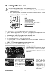
... top edge of the PCI Express slot to prevent hardware damage. Secure the card's metal bracket to install an expansion card: • Make sure the motherboard supports the expansion card. Example: Installing and Removing a PCI Express Graphics Card: • Installing a Graphics Card: Gently push down on the card are completely inserted...
... top edge of the PCI Express slot to prevent hardware damage. Secure the card's metal bracket to install an expansion card: • Make sure the motherboard supports the expansion card. Example: Installing and Removing a PCI Express Graphics Card: • Installing a Graphics Card: Gently push down on the card are completely inserted...
Manual
Page 19
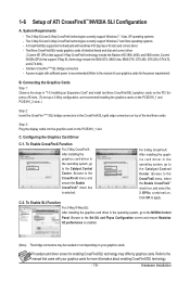
.... Browse to the NVIDIA Control Panel. Hardware Installation The 3-Way SLI and 3-Way CrossFireX technologies currently support Windows 7 and Vista operating systems - C. A CrossFireX/SLI-supported motherboard with sufficient power is selected. For 3-Way CrossFireX: After installing the graphics card driver in the operating system, go to the manual of identical brand...
.... Browse to the NVIDIA Control Panel. Hardware Installation The 3-Way SLI and 3-Way CrossFireX technologies currently support Windows 7 and Vista operating systems - C. A CrossFireX/SLI-supported motherboard with sufficient power is selected. For 3-Way CrossFireX: After installing the graphics card driver in the operating system, go to the manual of identical brand...

Manual
Page 20
..., make sure to turn off your system and the power switch on your SATA device. Step 2: Connect the SATA cable from the bracket to your motherboard. Step 3: Connect the power cable from the bracket to the SATA port on the power supply before installing or removing the SATA bracket and SATA...
..., make sure to turn off your system and the power switch on your SATA device. Step 2: Connect the SATA cable from the bracket to your motherboard. Step 3: Connect the power cable from the bracket to the SATA port on the power supply before installing or removing the SATA bracket and SATA...
Manual
Page 21
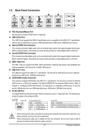
... connect a PS/2 mouse or keyboard. 1-8 Back Panel Connectors PS/2 Keyboard/Mouse Port Use this feature, ensure that your device and then remove it from the motherboard. • When removing the cable, pull it side to side to connect an external SATA device or a SATA port multiplier.
... connect a PS/2 mouse or keyboard. 1-8 Back Panel Connectors PS/2 Keyboard/Mouse Port Use this feature, ensure that your device and then remove it from the motherboard. • When removing the cable, pull it side to side to connect an external SATA device or a SATA port multiplier.
Manual
Page 23
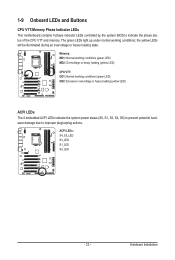
... conditions; the yellow LEDs will be illuminated during an overvoltage or heavy loading state. 1-9 Onboard LEDs and Buttons CPU VTT/Memory Phase Indicator LEDs This motherboard contains 4 phase indicator LEDs controlled by the system BIOS to improper plug/unplug actions. The green LEDs light up under normal working conditions (green LED...
... conditions; the yellow LEDs will be illuminated during an overvoltage or heavy loading state. 1-9 Onboard LEDs and Buttons CPU VTT/Memory Phase Indicator LEDs This motherboard contains 4 phase indicator LEDs controlled by the system BIOS to improper plug/unplug actions. The green LEDs light up under normal working conditions (green LED...
Manual
Page 24
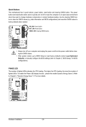
Quick Buttons This motherboard has 3 quick buttons: power button, reset button and clearing CMOS button. date information and BIOS configurations) and reset the CMOS values to clear the CMOS ...
Quick Buttons This motherboard has 3 quick buttons: power button, reset button and clearing CMOS button. date information and BIOS configurations) and reset the CMOS values to clear the CMOS ...


