Manual
Page 1
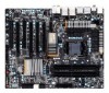
GA-P67A-UD7 LGA1155 socket motherboard for Intel® Core™ i7 processors/ Intel® Core™ i5 processors/ Intel® Core™ i3 processors/ Intel® Pentium® processors/ Intel® Celeron® processors User's Manual Rev. 1001 12ME-P67AUD7-1001R
GA-P67A-UD7 LGA1155 socket motherboard for Intel® Core™ i7 processors/ Intel® Core™ i5 processors/ Intel® Core™ i3 processors/ Intel® Pentium® processors/ Intel® Celeron® processors User's Manual Rev. 1001 12ME-P67AUD7-1001R
Manual
Page 7
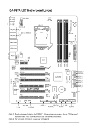
GA-P67A-UD7 Motherboard Layout KB_USB3 SYS_FAN1 R_SPDIF ATX_12V_2X USB_1394_ESATA_2 Marvell 88SE9128 USB_1394_ESATA_1 LGA1155 CPU_FAN PHASE LED PW_SW RST_SW PWR_FAN USB30_LAN2 CMOS_SW USB30_LAN1 VLI VL810 F_AUDIO AUDIO... limitation, the PCIEX1_1 slot can only accommodate a shorter PCI Express x1 expansion card. TSB43AB23 PCIEX8_2 GA-P67A-UD7 iTE IT8892 Bridge PCI2 VLI VL810 MD2 MD1 ATX DDR3_1 DDR3_2 DDR3_3 DDR3_4 IT8728 B_BIOS M_BIOS Intel® P67 BAT S4_S5_LED S3_LED S1_LED S0_LED Marvell 88SE9128 GSATA3_7 GSATA3_6 SATA3_1 SATA3_0 SATA2_3 SATA2_2 SATA2_5 SATA2_4...
GA-P67A-UD7 Motherboard Layout KB_USB3 SYS_FAN1 R_SPDIF ATX_12V_2X USB_1394_ESATA_2 Marvell 88SE9128 USB_1394_ESATA_1 LGA1155 CPU_FAN PHASE LED PW_SW RST_SW PWR_FAN USB30_LAN2 CMOS_SW USB30_LAN1 VLI VL810 F_AUDIO AUDIO... limitation, the PCIEX1_1 slot can only accommodate a shorter PCI Express x1 expansion card. TSB43AB23 PCIEX8_2 GA-P67A-UD7 iTE IT8892 Bridge PCI2 VLI VL810 MD2 MD1 ATX DDR3_1 DDR3_2 DDR3_3 DDR3_4 IT8728 B_BIOS M_BIOS Intel® P67 BAT S4_S5_LED S3_LED S1_LED S0_LED Marvell 88SE9128 GSATA3_7 GSATA3_6 SATA3_1 SATA3_0 SATA2_3 SATA2_2 SATA2_5 SATA2_4...
Manual
Page 8
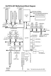
GA-P67A-UD7 Motherboard Block Diagram 2 PCI Express x8 2 PCI Express x8 LGA1155 CPU CPU CLK+/- (100 MHz) DDR3 2133/1866/1600/1333/1066 MHz Dual Channel Memory 1 PCI ... iTE IT8892 Bridge TSB43AB23 LAN1 DMI Interface RJ45 Realtek RTL8111E LAN2 RJ45 Realtek RTL8111E 2 SATA 6Gb/s Marvell 88SE9128 x1 x1 x1 PCIe CLK (100 MHz) Intel® P67 PCI Express Bus x1 Dual BIOS 2 SATA 6Gb/s Marvell 88SE9128 2 SATA 6Gb/s 4 SATA 3Gb/s 8 USB 2.0/1.1 (Note) CODEC LPC Bus IT8728 PS/2 KB/Mouse...
GA-P67A-UD7 Motherboard Block Diagram 2 PCI Express x8 2 PCI Express x8 LGA1155 CPU CPU CLK+/- (100 MHz) DDR3 2133/1866/1600/1333/1066 MHz Dual Channel Memory 1 PCI ... iTE IT8892 Bridge TSB43AB23 LAN1 DMI Interface RJ45 Realtek RTL8111E LAN2 RJ45 Realtek RTL8111E 2 SATA 6Gb/s Marvell 88SE9128 x1 x1 x1 PCIe CLK (100 MHz) Intel® P67 PCI Express Bus x1 Dual BIOS 2 SATA 6Gb/s Marvell 88SE9128 2 SATA 6Gb/s 4 SATA 3Gb/s 8 USB 2.0/1.1 (Note) CODEC LPC Bus IT8728 PS/2 KB/Mouse...

Manual
Page 15
... Follow the steps below to correctly install the CPU cooler on the motherboard. (The following procedure uses Intel® boxed cooler as the picture above shows, the installation is to your CPU cooler installation manual for instructions on the motherboard. Step 4: You should hear a "click" when pushing down on...The Top of Female Push Pin Female Push Pin Step 1: Apply an even and thin layer of thermal grease on the surface of the motherboard. Hardware Installation Inadequately removing the CPU cooler may adhere to the CPU fan header (CPU_FAN) on the male push pin. (Turning the ...
... Follow the steps below to correctly install the CPU cooler on the motherboard. (The following procedure uses Intel® boxed cooler as the picture above shows, the installation is to your CPU cooler installation manual for instructions on the motherboard. Step 4: You should hear a "click" when pushing down on...The Top of Female Push Pin Female Push Pin Step 1: Apply an even and thin layer of thermal grease on the surface of the motherboard. Hardware Installation Inadequately removing the CPU cooler may adhere to the CPU fan header (CPU_FAN) on the male push pin. (Turning the ...
Manual
Page 31
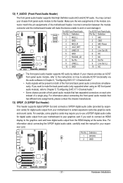
... audio output from the HDMI display at the same time. Pin No. Incorrect connection between the module connector and the motherboard header will be present on how to activate AC'97 functionality via the audio software in Chapter 5, "Configuring 2/4/5.1/7.1-Channel Audio... certain expansion cards like graphics cards and sound cards. If your expansion card. 12) F_AUDIO (Front Panel Audio Header) The front panel audio header supports Intel High Definition audio (HD) and AC'97 audio. Definition 1 MIC2_L 1 MIC 2 1 2 GND 3 MIC2_R 2 GND 3 MIC Power 4 -ACZ_DET 4 NC 5 LINE2_R...
... audio output from the HDMI display at the same time. Pin No. Incorrect connection between the module connector and the motherboard header will be present on how to activate AC'97 functionality via the audio software in Chapter 5, "Configuring 2/4/5.1/7.1-Channel Audio... certain expansion cards like graphics cards and sound cards. If your expansion card. 12) F_AUDIO (Front Panel Audio Header) The front panel audio header supports Intel High Definition audio (HD) and AC'97 audio. Definition 1 MIC2_L 1 MIC 2 1 2 GND 3 MIC2_R 2 GND 3 MIC Power 4 -ACZ_DET 4 NC 5 LINE2_R...

Manual
Page 52
...Disabled. Disabled Allows the SATA controllers to the fault or short. Enable Native IDE mode if you wish to Disabled. SATA Port0-3 Native Mode (Intel P67 Chipset) Specifies the operating mode of the attached LAN cable. Part1-2 Status = Open / Length = 0m Part3-6 Status = Open / ... Values +/-/PU/PD: Value F10: Save F6: Fail-Safe Defaults ESC: Exit F1: General Help F7: Optimized Defaults This motherboard incorporates cable diagnostic feature designed to be shared with other device. USB Legacy Function Allows USB keyboard to detect the status of ...
...Disabled. Disabled Allows the SATA controllers to the fault or short. Enable Native IDE mode if you wish to Disabled. SATA Port0-3 Native Mode (Intel P67 Chipset) Specifies the operating mode of the attached LAN cable. Part1-2 Status = Open / Length = 0m Part3-6 Status = Open / ... Values +/-/PU/PD: Value F10: Save F6: Fail-Safe Defaults ESC: Exit F1: General Help F7: Optimized Defaults This motherboard incorporates cable diagnostic feature designed to be shared with other device. USB Legacy Function Allows USB keyboard to detect the status of ...
Manual
Page 83
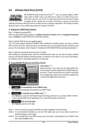
... controller driver first. All with which you run the X.H.D utility, back up all motherboard drivers, including the X.H.D utility. You can click the Xpress Install All button to ... damage or lost of a button, X.H.D helps to enhance your needs and hardware components. 3. Using GIGABYTE eXtreme Hard Drive (X.H.D) Instructions: (Note 2) Before launching X.H.D, make sure the new drive is added....Enter the system BIOS Setup program, set up a RAID-ready system and configure it for the Intel SATA controllers. A. To automatically set up a RAID 0 array: Click Auto to automatically and ...
... controller driver first. All with which you run the X.H.D utility, back up all motherboard drivers, including the X.H.D utility. You can click the Xpress Install All button to ... damage or lost of a button, X.H.D helps to enhance your needs and hardware components. 3. Using GIGABYTE eXtreme Hard Drive (X.H.D) Instructions: (Note 2) Before launching X.H.D, make sure the new drive is added....Enter the system BIOS Setup program, set up a RAID-ready system and configure it for the Intel SATA controllers. A. To automatically set up a RAID 0 array: Click Auto to automatically and ...

Manual
Page 87
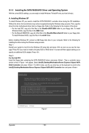
... driver (Note 2) and operating system. Installing SATA hard drive(s) in your computer Attach one hard drive. • Windows 7/Vista/XP setup disk. • Motherboard driver disk. 5-1-1 Configuring Intel P67 SATA Controllers A. Chapter 5 Appendix 5-1 Configuring SATA Hard Drive(s) To configure SATA hard drive(s), follow the steps below: A. Configure SATA controller mode in RAID...
... driver (Note 2) and operating system. Installing SATA hard drive(s) in your computer Attach one hard drive. • Windows 7/Vista/XP setup disk. • Motherboard driver disk. 5-1-1 Configuring Intel P67 SATA Controllers A. Chapter 5 Appendix 5-1 Configuring SATA Hard Drive(s) To configure SATA hard drive(s), follow the steps below: A. Configure SATA controller mode in RAID...
Manual
Page 100
...mode, use with Windows, using a device support disk provided by an adapter manufacturer. Intel(R) ICH7R/DH SATA RAID Controller Intel(R) ICH7MDH SATA RAID Controller Intel(R) Desktop/Workstation/Server Express Chipset SATA RAID Controller Intel(R) Mobile Express Chipset SATA RAID Controller ENTER=Select F3=Exit Figure 1 Appendix - ...; For the Marvell 88SE9128, copy all of the files in the \BootDrv\iRST\32Bit folder to your system to boot from the motherboard driver disk to a floppy disk. Press . Installing Windows XP To install Windows XP, you to your hard drive(s). Step 1: ...
...mode, use with Windows, using a device support disk provided by an adapter manufacturer. Intel(R) ICH7R/DH SATA RAID Controller Intel(R) ICH7MDH SATA RAID Controller Intel(R) Desktop/Workstation/Server Express Chipset SATA RAID Controller Intel(R) Mobile Express Chipset SATA RAID Controller ENTER=Select F3=Exit Figure 1 Appendix - ...; For the Marvell 88SE9128, copy all of the files in the \BootDrv\iRST\32Bit folder to your system to boot from the motherboard driver disk to a floppy disk. Press . Installing Windows XP To install Windows XP, you to your hard drive(s). Step 1: ...
Manual
Page 103
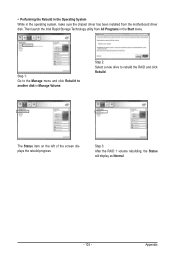
... the RAID and click Rebuild. Step 3: After the RAID 1 volume rebuilding, the Status will display as Normal. - 103 - Appendix Then launch the Intel Rapid Storage Technology utility from the motherboard driver disk. The Status item on the left of the screen displays the rebuild progress. Step 2: Select a new drive to another disk...
... the RAID and click Rebuild. Step 3: After the RAID 1 volume rebuilding, the Status will display as Normal. - 103 - Appendix Then launch the Intel Rapid Storage Technology utility from the motherboard driver disk. The Status item on the left of the screen displays the rebuild progress. Step 2: Select a new drive to another disk...


