
Manual
Page 1
Setting Up a RAID-Ready System Step 1: Configure the system BIOS Enter the system BIOS Setup program, set up a RAID-ready system and configure it for complex and time-consuming configurations. To manually set up a RAID 0 array later ... System." ) Step 3: Install the motherboard drivers and the X.H.D utiltiy After installing the operating system, insert the motherboard driver disk. B. A. eXtreme Hard Drive (X.H.D) With GIGABYTE eXtreme Hard Drive (X.H.D)(Note 1), users can click the Xpress Install All button to automatically install all of your data to avoid risk of hardware damage...
Setting Up a RAID-Ready System Step 1: Configure the system BIOS Enter the system BIOS Setup program, set up a RAID-ready system and configure it for complex and time-consuming configurations. To manually set up a RAID 0 array later ... System." ) Step 3: Install the motherboard drivers and the X.H.D utiltiy After installing the operating system, insert the motherboard driver disk. B. A. eXtreme Hard Drive (X.H.D) With GIGABYTE eXtreme Hard Drive (X.H.D)(Note 1), users can click the Xpress Install All button to automatically install all of your data to avoid risk of hardware damage...
Manual
Page 3
...in this manual may be reproduced, copied, translated, transmitted, or published in this product, GIGABYTE provides the following types of documentations: For quick set-up of GIGABYTE. Changes to use of this manual may be made by copyright laws and is the ...information, carefully read or download the information on/from the Support&Downloads\Motherboard\Technology Guide page on your motherboard revision before updating motherboard BIOS, drivers, or when looking for technical information. For example, "REV: 1.0" means the revision of this manual are legally registered to...
...in this manual may be reproduced, copied, translated, transmitted, or published in this product, GIGABYTE provides the following types of documentations: For quick set-up of GIGABYTE. Changes to use of this manual may be made by copyright laws and is the ...information, carefully read or download the information on/from the Support&Downloads\Motherboard\Technology Guide page on your motherboard revision before updating motherboard BIOS, drivers, or when looking for technical information. For example, "REV: 1.0" means the revision of this manual are legally registered to...
Manual
Page 4
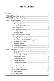
Table of Contents Box Contents...6 Optional Items...6 GA-P55A-UD7 Motherboard Layout 7 GA-P55A-UD7 Motherboard Block Diagram 8 Chapter 1 Hardware Installation 9 1-1 Installation Precautions 9 1-2 Product Specifications 10 1-3 Installing the CPU and CPU Cooler 13 ... Connectors 22 1-10 Onboard LEDs and Buttons 24 1-11 Internal Connectors 26 Chapter 2 BIOS Setup 37 2-1 Startup Screen 38 2-2 The Main Menu 39 2-3 MB Intelligent Tweaker(M.I.T 41 2-4 Standard CMOS Features 50 2-5 Advanced BIOS Features 52 2-6 Integrated Peripherals 54 2-7 Power Management Setup 58 2-8 PC Health Status...
Table of Contents Box Contents...6 Optional Items...6 GA-P55A-UD7 Motherboard Layout 7 GA-P55A-UD7 Motherboard Block Diagram 8 Chapter 1 Hardware Installation 9 1-1 Installation Precautions 9 1-2 Product Specifications 10 1-3 Installing the CPU and CPU Cooler 13 ... Connectors 22 1-10 Onboard LEDs and Buttons 24 1-11 Internal Connectors 26 Chapter 2 BIOS Setup 37 2-1 Startup Screen 38 2-2 The Main Menu 39 2-3 MB Intelligent Tweaker(M.I.T 41 2-4 Standard CMOS Features 50 2-5 Advanced BIOS Features 52 2-6 Integrated Peripherals 54 2-7 Power Management Setup 58 2-8 PC Health Status...

Manual
Page 5
......68 Chapter 4 Unique Features 69 4-1 Xpress Recovery2 69 4-2 BIOS Update Utilities 72 4-2-1 Updating the BIOS with the Q-Flash Utility 72 4-2-2 Updating the BIOS with the @BIOS Utility 75 4-3 EasyTune 6...76 4-4 Dynamic Energy SaverTM 2 77... 4-5 Q-Share...79 4-6 Smart 6™ ...80 4-7 Auto Green...83 4-8 eXtreme Hard Drive (X.H.D 84 4-9 Teaming 85 Chapter 5 Appendix...87 5-1 Configuring SATA Hard Drive(s 87 5-1-1 Configuring Intel P55 SATA Controllers 87 5-1-2 Configuring JMicron JMB362/GIGABYTE...
......68 Chapter 4 Unique Features 69 4-1 Xpress Recovery2 69 4-2 BIOS Update Utilities 72 4-2-1 Updating the BIOS with the Q-Flash Utility 72 4-2-2 Updating the BIOS with the @BIOS Utility 75 4-3 EasyTune 6...76 4-4 Dynamic Energy SaverTM 2 77... 4-5 Q-Share...79 4-6 Smart 6™ ...80 4-7 Auto Green...83 4-8 eXtreme Hard Drive (X.H.D 84 4-9 Teaming 85 Chapter 5 Appendix...87 5-1 Configuring SATA Hard Drive(s 87 5-1-1 Configuring Intel P55 SATA Controllers 87 5-1-2 Configuring JMicron JMB362/GIGABYTE...
Manual
Page 8
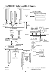
GA-P55A-UD7 Motherboard Block Diagram 2 PCI Express x8 2 PCI Express x8 LGA1156 CPU CPU CLK+/- (133 MHz) DDR3 2200/1333/1066/800 MHz Dual Channel Memory 1 PCI ... 3 IEEE 1394a DMI Interface LAN1 LAN2 2 SATA 3Gb/s RJ45 ATA-133/100/66/33 RJ45 GIGABYTE IDE Channel RTL8111D RTL8111D SATA2 Intel® P55 x1 x1 x1 PCIe CLK (100 MHz) PCI Express Bus x1 Dual BIOS JMicron JMB362 6 SATA 3Gb/s 2 SATA 3Gb/s 14 USB 2.0/1.1 (Note) CODEC LPC Bus IT8720 Floppy COM...
GA-P55A-UD7 Motherboard Block Diagram 2 PCI Express x8 2 PCI Express x8 LGA1156 CPU CPU CLK+/- (133 MHz) DDR3 2200/1333/1066/800 MHz Dual Channel Memory 1 PCI ... 3 IEEE 1394a DMI Interface LAN1 LAN2 2 SATA 3Gb/s RJ45 ATA-133/100/66/33 RJ45 GIGABYTE IDE Channel RTL8111D RTL8111D SATA2 Intel® P55 x1 x1 x1 PCIe CLK (100 MHz) PCI Express Bus x1 Dual BIOS JMicron JMB362 6 SATA 3Gb/s 2 SATA 3Gb/s 14 USB 2.0/1.1 (Note) CODEC LPC Bus IT8720 Floppy COM...

Manual
Page 12
... depend on the CPU/system cooler you are installing two PCI Express graphics cards, it in EasyTune may differ by motherboard model. I/O Controller w Hardware Monitor w w w w w w BIOS w w w w Unique Features w w w w w w w w w w w w Bundled Software w iTE IT8720 chip System voltage detection CPU/System temperature detection CPU/System/Power fan speed detection CPU overheating warning CPU/System...
... depend on the CPU/system cooler you are installing two PCI Express graphics cards, it in EasyTune may differ by motherboard model. I/O Controller w Hardware Monitor w w w w w w BIOS w w w w Unique Features w w w w w w w w w w w w Bundled Software w iTE IT8720 chip System voltage detection CPU/System temperature detection CPU/System/Power fan speed detection CPU overheating warning CPU/System...

Manual
Page 17
...to prevent hardware damage. • Memory modules have a foolproof design. If only one DDR3 memory module is installed, be used . (Go to GIGABYTE's website for optimum performance. It is installed. 2. The four DDR3 memory sockets are unable to CPU limitations, read the following : Channel 0: DDR3_1...: • Make sure that memory of the same capacity, brand, speed, and chips be sure to install it is installed, the BIOS will double the original memory bandwidth. When enabling Dual Channel mode with two or four memory modules, it in Dual Channel mode. 1. ...
...to prevent hardware damage. • Memory modules have a foolproof design. If only one DDR3 memory module is installed, be used . (Go to GIGABYTE's website for optimum performance. It is installed. 2. The four DDR3 memory sockets are unable to CPU limitations, read the following : Channel 0: DDR3_1...: • Make sure that memory of the same capacity, brand, speed, and chips be sure to install it is installed, the BIOS will double the original memory bandwidth. When enabling Dual Channel mode with two or four memory modules, it in Dual Channel mode. 1. ...
Manual
Page 19
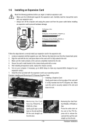
.../PCIEX16_2) PCI Express x16 Slot (PCIEX8_1/PCIEX8_2) PCI Slot Follow the steps below to correctly install your computer. If necessary, go to BIOS Setup to make any required BIOS changes for your operating system. 1-6 Installing an Expansion Card Read the following guidelines before installing an expansion card to prevent hardware damage. Remove...
.../PCIEX16_2) PCI Express x16 Slot (PCIEX8_1/PCIEX8_2) PCI Slot Follow the steps below to correctly install your computer. If necessary, go to BIOS Setup to make any required BIOS changes for your operating system. 1-6 Installing an Expansion Card Read the following guidelines before installing an expansion card to prevent hardware damage. Remove...

Manual
Page 24
...): GD1: Normal working conditions; 1-10 Onboard LEDs and Buttons CPU VTT/Memory Phase Indicator LEDs This motherboard contains 4 phase indicator LEDs controlled by the system BIOS to improper plug/unplug actions. ACPI LEDs: S4_S5_LED S3_LED S1_LED S0_LED Hardware Installation - 24 -
...): GD1: Normal working conditions; 1-10 Onboard LEDs and Buttons CPU VTT/Memory Phase Indicator LEDs This motherboard contains 4 phase indicator LEDs controlled by the system BIOS to improper plug/unplug actions. ACPI LEDs: S4_S5_LED S3_LED S1_LED S0_LED Hardware Installation - 24 -

Manual
Page 25
date information and BIOS configurations) and reset the CMOS values to clear the CMOS values (e.g. PHASE LED The Phase LEDs ... the CMOS values. • After system restart, go to BIOS Setup to load factory defaults (select Load Optimized Defaults) or manually configure the BIOS settings (refer to Chapter 4, "Dynamic Energy Saver™ 2," for BIOS configurations). To enable the PHASE LED display function, please first...-case environment when they want to change hardware components or conduct hardware testing. Refer to Chapter 2, "BIOS Setup," for more the number of lighted LEDs.
date information and BIOS configurations) and reset the CMOS values to clear the CMOS values (e.g. PHASE LED The Phase LEDs ... the CMOS values. • After system restart, go to BIOS Setup to load factory defaults (select Load Optimized Defaults) or manually configure the BIOS settings (refer to Chapter 4, "Dynamic Energy Saver™ 2," for BIOS configurations). To enable the PHASE LED display function, please first...-case environment when they want to change hardware components or conduct hardware testing. Refer to Chapter 2, "BIOS Setup," for more the number of lighted LEDs.

Manual
Page 31
Each SATA connector supports a single SATA device. Refer to keep the values (such as BIOS configurations, date, and time information) in the power cord and restart your computer. • Always turn off your computer and unplug the power cord before ...
Each SATA connector supports a single SATA device. Refer to keep the values (such as BIOS configurations, date, and time information) in the power cord and restart your computer. • Always turn off your computer and unplug the power cord before ...

Manual
Page 32
...startup status by chassis. The LED is on when the hard drive is operating. When connecting your system using the power switch (refer to Chapter 2, "BIOS Setup," "Power Management Setup," for information about beep codes. • HD (Hard Drive Activity LED, Blue) Connects to the speaker on the chassis ... activity LED, speaker and etc. If a problem is detected at system startup. One single short beep will be heard if no problem is detected, the BIOS may differ by issuing a beep code. RESRES+ CICI+ PWR+ PWR- The LED keeps blinking when the sys- This function requires a chassis with a ...
...startup status by chassis. The LED is on when the hard drive is operating. When connecting your system using the power switch (refer to Chapter 2, "BIOS Setup," "Power Management Setup," for information about beep codes. • HD (Hard Drive Activity LED, Blue) Connects to the speaker on the chassis ... activity LED, speaker and etc. If a problem is detected at system startup. One single short beep will be heard if no problem is detected, the BIOS may differ by issuing a beep code. RESRES+ CICI+ PWR+ PWR- The LED keeps blinking when the sys- This function requires a chassis with a ...

Manual
Page 37
... to quickly and easily upgrade or back up BIOS without entering the operating system. • @BIOS is recommended that searches and downloads the latest version of BIOS from the Internet and updates the BIOS. To upgrade the BIOS, use either the GIGABYTE Q-Flash or @BIOS utility. • Q-Flash allows the user ... it is a Windows-based utility that you need to) to the "Load Optimized Defaults" section in this chapter or introductions of BIOS, it with caution. When the power is turned off, the battery on the motherboard supplies the necessary power to the CMOS to clear...
... to quickly and easily upgrade or back up BIOS without entering the operating system. • @BIOS is recommended that searches and downloads the latest version of BIOS from the Internet and updates the BIOS. To upgrade the BIOS, use either the GIGABYTE Q-Flash or @BIOS utility. • Q-Flash allows the user ... it is a Windows-based utility that you need to) to the "Load Optimized Defaults" section in this chapter or introductions of BIOS, it with caution. When the power is turned off, the battery on the motherboard supplies the necessary power to the CMOS to clear...

Manual
Page 38
...BIOS Version P55A-UD7 D25 . . . . : BIOS Setup : XpressRecovery2 : Boot Menu : Qflash 01/05/2010-P55-7A89TG06C-00 Function Keys Function Keys Function Keys: : POST SCREEN Press the key to show the BIOS POST screen at system startup, refer to the instructions on the Full Screen LOGO Show item on BIOS Setup settings. BIOS...will still be used for one time only. Note: The setting in Boot Menu. The LOGO Screen (Default) B. To show the BIOS POST screen. For more information, refer to Chapter 4, "Xpress Recovery2." : BOOT MENU Boot Menu allows you have ever entered Xpress ...
...BIOS Version P55A-UD7 D25 . . . . : BIOS Setup : XpressRecovery2 : Boot Menu : Qflash 01/05/2010-P55-7A89TG06C-00 Function Keys Function Keys Function Keys: : POST SCREEN Press the key to show the BIOS POST screen at system startup, refer to the instructions on the Full Screen LOGO Show item on BIOS Setup settings. BIOS...will still be used for one time only. Note: The setting in Boot Menu. The LOGO Screen (Default) B. To show the BIOS POST screen. For more information, refer to Chapter 4, "Xpress Recovery2." : BOOT MENU Boot Menu allows you have ever entered Xpress ...

Manual
Page 39
... & Exit Setup Exit Without Saving ESC: Quit F8: Q-Flash Select Item F10: Save & Exit Setup F11: Save CMOS to BIOS F12: Load CMOS from BIOS BIOS Setup Program Function Keys Move the selection bar to select an item Execute command or enter the submenu Main Menu: Exit the... settings for the current submenus Access the Q-Flash utility Display system information Save all the changes and exit the BIOS Setup program Save CMOS to BIOS Load CMOS from BIOS Main Menu Help The on-screen description of a highlighted setup option is displayed on the bottom line of the ...
... & Exit Setup Exit Without Saving ESC: Quit F8: Q-Flash Select Item F10: Save & Exit Setup F11: Save CMOS to BIOS F12: Load CMOS from BIOS BIOS Setup Program Function Keys Move the selection bar to select an item Execute command or enter the submenu Main Menu: Exit the... settings for the current submenus Access the Q-Flash utility Display system information Save all the changes and exit the BIOS Setup program Save CMOS to BIOS Load CMOS from BIOS Main Menu Help The on-screen description of a highlighted setup option is displayed on the bottom line of the ...

Manual
Page 40
... for optimal-performance system operations. Set Supervisor Password Change, set , or disable password. You can create up to the system and BIOS Setup. First select the profile you wish to load, then press to complete. MB Intelligent Tweaker(M.I.T.) Use this menu to configure the...61565; F12: Load CMOS from a profile created before, without the hassles of errors that stop the system boot, etc. Advanced BIOS Features Use this menu to configure the device boot order, advanced features available on the CPU, and the primary display adapter. Integrated ...
... for optimal-performance system operations. Set Supervisor Password Change, set , or disable password. You can create up to the system and BIOS Setup. First select the profile you wish to load, then press to complete. MB Intelligent Tweaker(M.I.T.) Use this menu to configure the...61565; F12: Load CMOS from a profile created before, without the hassles of errors that stop the system boot, etc. Advanced BIOS Features Use this menu to configure the device boot order, advanced features available on the CPU, and the primary display adapter. Integrated ...

Manual
Page 41
... overclock/overvoltage may result in damage to boot. Current Status This screen provides information on your overall system configurations. BIOS Setup This page is for advanced users only and we recommend you made is dependent on CPU/memory frequencies/parameters....Voltage Settings } Miscellaneous Settings [Press Enter] [Press Enter] [Press Enter] [Press Enter] [Press Enter] Item Help Menu Level BIOS Version BCLK CPU Frequency Memory Frequency Total Memory Size D25 133.27 MHz 3198.42 MHz 1332.80 MHz 1024 MB CPU Temperature PCH Temperature...
... overclock/overvoltage may result in damage to boot. Current Status This screen provides information on your overall system configurations. BIOS Setup This page is for advanced users only and we recommend you made is dependent on CPU/memory frequencies/parameters....Voltage Settings } Miscellaneous Settings [Press Enter] [Press Enter] [Press Enter] [Press Enter] [Press Enter] Item Help Menu Level BIOS Version BCLK CPU Frequency Memory Frequency Total Memory Size D25 133.27 MHz 3198.42 MHz 1332.80 MHz 1024 MB CPU Temperature PCH Temperature...

Manual
Page 42
...) (Note) Enables or disables Intel CPU Enhanced Halt (C1E) function, a CPU power-saving function in system halt state. Auto lets the BIOS automatically configure this function. All Enables all CPU cores. CPU Clock Ratio Allows you to enable the Intel CPU Turbo Boost technology. Auto lets ...to enable all CPU cores. (Default) 1 Enables only one CPU core. 2 Enables only two CPU cores. 3 Enables only three CPU cores. BIOS Setup - 42 - CPU Multi-Threading (Note) Allows you to determine whether to enable multi-threading technology when using an Intel CPU that supports ...
...) (Note) Enables or disables Intel CPU Enhanced Halt (C1E) function, a CPU power-saving function in system halt state. Auto lets the BIOS automatically configure this function. All Enables all CPU cores. CPU Clock Ratio Allows you to enable the Intel CPU Turbo Boost technology. Auto lets ...to enable all CPU cores. (Default) 1 Enables only one CPU core. 2 Enables only two CPU cores. 3 Enables only three CPU cores. BIOS Setup - 42 - CPU Multi-Threading (Note) Allows you to determine whether to enable multi-threading technology when using an Intel CPU that supports ...

Manual
Page 43
...being installed. QPI Clock Ratio Allows you to decrease average power consumption and heat production. The adjustable range is enabled. BIOS Setup Auto lets the BIOS automatically configure this setting. (Default: Auto) CPU Thermal Monitor (Note) Enables or disables Intel CPU Thermal Monitor function...website. - 43 - C3/C6/C7 State Support (Note) Allows you to determine whether to decrease heat production. Auto lets the BIOS automatically configure this setting. (Default: Auto) CPU EIST Function (Note) Enables or disables Enhanced Intel SpeedStep Technology (EIST). QPI Link ...
...being installed. QPI Clock Ratio Allows you to decrease average power consumption and heat production. The adjustable range is enabled. BIOS Setup Auto lets the BIOS automatically configure this setting. (Default: Auto) CPU Thermal Monitor (Note) Enables or disables Intel CPU Thermal Monitor function...website. - 43 - C3/C6/C7 State Support (Note) Allows you to determine whether to decrease heat production. Auto lets the BIOS automatically configure this setting. (Default: Auto) CPU EIST Function (Note) Enables or disables Enhanced Intel SpeedStep Technology (EIST). QPI Link ...

Manual
Page 44
...adjustable range is the normal operating frequency of the CPU and the Chipset clock. Options are : 700mV, 800mV (default), 900mV, 1000mV. BIOS Setup - 44 - CPU Clock Skew Allows you to set the system memory multiplier. System Memory Multiplier (SPD) Allows you to memory SPD...: 700mV, 800mV, 900mV (default), 1000mV. PCI Express Frequency(Mhz) Allows you to the Chipset clock. Extreme Memory Profile (X.M.P.) (Note) Allows the BIOS to read the SPD data on XMP memory module(s) to 150 MHz. Disabled Disables this feature. Profile2 (Note) Uses Profile 2 settings. Auto sets...
...adjustable range is the normal operating frequency of the CPU and the Chipset clock. Options are : 700mV, 800mV (default), 900mV, 1000mV. BIOS Setup - 44 - CPU Clock Skew Allows you to set the system memory multiplier. System Memory Multiplier (SPD) Allows you to memory SPD...: 700mV, 800mV, 900mV (default), 1000mV. PCI Express Frequency(Mhz) Allows you to the Chipset clock. Extreme Memory Profile (X.M.P.) (Note) Allows the BIOS to read the SPD data on XMP memory module(s) to 150 MHz. Disabled Disables this feature. Profile2 (Note) Uses Profile 2 settings. Auto sets...


