
Manual
Page 1
... "Installing the SATA RAID/AHCI Driver and Operating System." ) Step 3: Install the motherboard drivers and the X.H.D utiltiy After installing the operating system, insert the motherboard driver disk. B. Using GIGABYTE eXtreme Hard Drive (X.H.D) Instructions:(Note 2) Before launching X.H.D, make sure the new drive is... drive is added. Setting Up a RAID-Ready System Step 1: Configure the system BIOS Enter the system BIOS Setup program, set up all motherboard drivers, including the X.H.D utility. For a RAID 0 array that before you run the X.H.D utility, back up a RAID array: (Note...
... "Installing the SATA RAID/AHCI Driver and Operating System." ) Step 3: Install the motherboard drivers and the X.H.D utiltiy After installing the operating system, insert the motherboard driver disk. B. Using GIGABYTE eXtreme Hard Drive (X.H.D) Instructions:(Note 2) Before launching X.H.D, make sure the new drive is... drive is added. Setting Up a RAID-Ready System Step 1: Configure the system BIOS Enter the system BIOS Setup program, set up all motherboard drivers, including the X.H.D utility. For a RAID 0 array that before you run the X.H.D utility, back up a RAID array: (Note...
Manual
Page 1
GA-P55A-UD7 LGA1156 socket motherboard for Intel® Core™ i7 processor family/ Intel® Core™ i5 processor family/Intel® Core™ i3 processor family User's Manual Rev. 1001 12ME-P55AUD7-1001R
GA-P55A-UD7 LGA1156 socket motherboard for Intel® Core™ i7 processor family/ Intel® Core™ i5 processor family/Intel® Core™ i3 processor family User's Manual Rev. 1001 12ME-P55AUD7-1001R
Manual
Page 2
Motherboard GA-P55A-UD7 Jan. 26, 2010 Motherboard GA-P55A-UD7 Jan. 26, 2010
Motherboard GA-P55A-UD7 Jan. 26, 2010 Motherboard GA-P55A-UD7 Jan. 26, 2010
Manual
Page 3
... manual may be made by any form or by GIGABYTE without GIGABYTE's prior written permission. For product-related information, check on our website at: http://www.gigabyte.com.tw Identifying Your Motherboard Revision The revision number on our website. Changes to...in any means without prior notice. No part of GIGABYTE. For detailed product information, carefully read or download the information on/from the Support&Downloads\Motherboard\Technology Guide page on your motherboard revision before updating motherboard BIOS, drivers, or when looking for technical information....
... manual may be made by any form or by GIGABYTE without GIGABYTE's prior written permission. For product-related information, check on our website at: http://www.gigabyte.com.tw Identifying Your Motherboard Revision The revision number on our website. Changes to...in any means without prior notice. No part of GIGABYTE. For detailed product information, carefully read or download the information on/from the Support&Downloads\Motherboard\Technology Guide page on your motherboard revision before updating motherboard BIOS, drivers, or when looking for technical information....
Manual
Page 4
Table of Contents Box Contents...6 Optional Items...6 GA-P55A-UD7 Motherboard Layout 7 GA-P55A-UD7 Motherboard Block Diagram 8 Chapter 1 Hardware Installation 9 1-1 Installation Precautions 9 1-2 Product Specifications 10 1-3 Installing the CPU and CPU Cooler 13 1-3-1 Installing the CPU 13 1-3-2 Installing the CPU Cooler ...
Table of Contents Box Contents...6 Optional Items...6 GA-P55A-UD7 Motherboard Layout 7 GA-P55A-UD7 Motherboard Block Diagram 8 Chapter 1 Hardware Installation 9 1-1 Installation Precautions 9 1-2 Product Specifications 10 1-3 Installing the CPU and CPU Cooler 13 1-3-1 Installing the CPU 13 1-3-2 Installing the CPU Cooler ...
Manual
Page 6
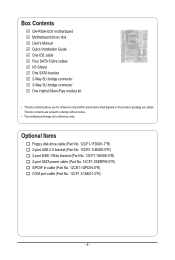
... SATA power cable (Part No. 12CF1-2SERPW-0*R) S/PDIF In cable (Part No. 12CR1-1SPDIN-0*R) COM port cable (Part No. 12CF1-1CM001-3*R) - 6 - Box Contents GA-P55A-UD7 motherboard Motherboard driver disk User's Manual Quick Installation Guide One IDE cable Four SATA 3Gb/s cables I/O Shield One SATA bracket 2-Way SLI bridge connector 3-Way SLI bridge... connector One Hybrid Silent-Pipe module kit • The box contents above are subject to change without notice. • The motherboard image is for reference only and the actual items shall depend on the product package you obtain.
... SATA power cable (Part No. 12CF1-2SERPW-0*R) S/PDIF In cable (Part No. 12CR1-1SPDIN-0*R) COM port cable (Part No. 12CF1-1CM001-3*R) - 6 - Box Contents GA-P55A-UD7 motherboard Motherboard driver disk User's Manual Quick Installation Guide One IDE cable Four SATA 3Gb/s cables I/O Shield One SATA bracket 2-Way SLI bridge connector 3-Way SLI bridge... connector One Hybrid Silent-Pipe module kit • The box contents above are subject to change without notice. • The motherboard image is for reference only and the actual items shall depend on the product package you obtain.
Manual
Page 7
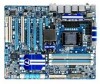
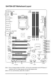
GA-P55A-UD7 Motherboard Layout KB_USB R_SPDIF SYS_FAN3 ATX_12V_2X USB_1394_ESATA_2 USB_1394_ESATA_1 USB_LAN LGA1156 CPU_FAN PW_SW ATX M_P_LED V_P_LED PWR_FAN USB30_LAN AUDIO JMicron JMB362 NEC D720200F1 F_AUDIO PCIEX1_1 (Note 1) RTL8111D PCH_FAN RTL8111D NF200 PEX8608 Bridge PCIEX16_1 DDR3_2 DDR3_1 DDR3_4 DDR3_3 PHASE LED GIGABYTE... SATA2 IDE GSATA2_7 GSATA2_6 PCIEX8_1 SATA2_1 SATA2_0 CODEC CD_IN SPDIF_I PCIEX16_2 PCI1 SPDIF_O PCIEX8_2GA-P55A-UD7 B_BIOS Intel® P55 M_BIOS TSB43AB23 S4_S5_LED S3_LED...
GA-P55A-UD7 Motherboard Layout KB_USB R_SPDIF SYS_FAN3 ATX_12V_2X USB_1394_ESATA_2 USB_1394_ESATA_1 USB_LAN LGA1156 CPU_FAN PW_SW ATX M_P_LED V_P_LED PWR_FAN USB30_LAN AUDIO JMicron JMB362 NEC D720200F1 F_AUDIO PCIEX1_1 (Note 1) RTL8111D PCH_FAN RTL8111D NF200 PEX8608 Bridge PCIEX16_1 DDR3_2 DDR3_1 DDR3_4 DDR3_3 PHASE LED GIGABYTE... SATA2 IDE GSATA2_7 GSATA2_6 PCIEX8_1 SATA2_1 SATA2_0 CODEC CD_IN SPDIF_I PCIEX16_2 PCI1 SPDIF_O PCIEX8_2GA-P55A-UD7 B_BIOS Intel® P55 M_BIOS TSB43AB23 S4_S5_LED S3_LED...
Manual
Page 8
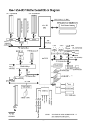
GA-P55A-UD7 Motherboard Block Diagram 2 PCI Express x8 2 PCI Express x8 LGA1156 CPU CPU CLK+/- (133 MHz) DDR3 2200/1333/1066/800 MHz Dual Channel Memory 1 PCI Express ... PCI Express Bus Marvell 9128 2 SATA 6Gb/s PCI Bus TSB43AB23 3 IEEE 1394a DMI Interface LAN1 LAN2 2 SATA 3Gb/s RJ45 ATA-133/100/66/33 RJ45 GIGABYTE IDE Channel RTL8111D RTL8111D SATA2 Intel® P55 x1 x1 x1 PCIe CLK (100 MHz) PCI Express Bus x1 Dual BIOS JMicron JMB362 6 SATA 3Gb...
GA-P55A-UD7 Motherboard Block Diagram 2 PCI Express x8 2 PCI Express x8 LGA1156 CPU CPU CLK+/- (133 MHz) DDR3 2200/1333/1066/800 MHz Dual Channel Memory 1 PCI Express ... PCI Express Bus Marvell 9128 2 SATA 6Gb/s PCI Bus TSB43AB23 3 IEEE 1394a DMI Interface LAN1 LAN2 2 SATA 3Gb/s RJ45 ATA-133/100/66/33 RJ45 GIGABYTE IDE Channel RTL8111D RTL8111D SATA2 Intel® P55 x1 x1 x1 PCIe CLK (100 MHz) PCI Express Bus x1 Dual BIOS JMicron JMB362 6 SATA 3Gb...

Manual
Page 9
... (ESD) wrist strap when handling electronic com- Hardware Installation If you are connected tightly and securely. • When handling the motherboard, avoid touching any installation steps or have it on top of an antistatic pad or within the computer casing. • Do...Before using the product, please verify that all cables and power connectors of your dealer. Chapter 1 Hardware Installation 1-1 Installation Precautions The motherboard contains numerous delicate electronic circuits and components which can lead to damage to system components as well as physical harm to the user....
... (ESD) wrist strap when handling electronic com- Hardware Installation If you are connected tightly and securely. • When handling the motherboard, avoid touching any installation steps or have it on top of an antistatic pad or within the computer casing. • Do...Before using the product, please verify that all cables and power connectors of your dealer. Chapter 1 Hardware Installation 1-1 Installation Precautions The motherboard contains numerous delicate electronic circuits and components which can lead to damage to system components as well as physical harm to the user....

Manual
Page 12
... 4 GB. (Note 2) For optimum performance, if only one PCI Express graphics card is recommended that you install. (Note 6) Available functions in EasyTune may differ by motherboard model. if you are installing two PCI Express graphics cards, it in the PCIEX16_1 and PCIEX16_2 slots. (Note 3) The PCIEX8_1 slot shares bandwidth with the...
... 4 GB. (Note 2) For optimum performance, if only one PCI Express graphics card is recommended that you install. (Note 6) Available functions in EasyTune may differ by motherboard model. if you are installing two PCI Express graphics cards, it in the PCIEX16_1 and PCIEX16_2 slots. (Note 3) The PCIEX8_1 slot shares bandwidth with the...

Manual
Page 13
Locate the alignment keys on the motherboard CPU socket and the notches on the CPU - 13 - The CPU cannot be set the frequency beyond hardware specifications since it does not meet the ... the computer and unplug the power cord from the power outlet before you begin to install the CPU: • Make sure that the motherboard supports the CPU. (Go to GIGABYTE's website for the peripherals. LGA1156 CPU Socket Alignment Key Alignment Key Pin One Corner of the CPU. • Do not turn on...
Locate the alignment keys on the motherboard CPU socket and the notches on the CPU - 13 - The CPU cannot be set the frequency beyond hardware specifications since it does not meet the ... the computer and unplug the power cord from the power outlet before you begin to install the CPU: • Make sure that the motherboard supports the CPU. (Go to GIGABYTE's website for the peripherals. LGA1156 CPU Socket Alignment Key Alignment Key Pin One Corner of the CPU. • Do not turn on...

Manual
Page 14
... pin one marking (triangle) with the socket alignment keys) and gently insert the CPU into position. Step 5: Push the CPU socket lever back into the motherboard CPU socket. NOTE: Hold the CPU socket lever by the handle, not the lever base portion. Step 1: Gently press the CPU socket lever handle down...
... pin one marking (triangle) with the socket alignment keys) and gently insert the CPU into position. Step 5: Push the CPU socket lever back into the motherboard CPU socket. NOTE: Hold the CPU socket lever by the handle, not the lever base portion. Step 1: Gently press the CPU socket lever handle down...

Manual
Page 15
...to the CPU. Step 4: You should hear a "click" when pushing down on the motherboard. 1-3-2 Installing the CPU Cooler Follow the steps below to correctly install the CPU cooler on the motherboard. (The following procedure uses Intel® boxed cooler as the picture above shows, the installation... is complete. Step 6: Finally, attach the power connector of the motherboard. Hardware Installation Push down each push pin. Use extreme care when removing the CPU cooler because the thermal grease/tape between the CPU...
...to the CPU. Step 4: You should hear a "click" when pushing down on the motherboard. 1-3-2 Installing the CPU Cooler Follow the steps below to correctly install the CPU cooler on the motherboard. (The following procedure uses Intel® boxed cooler as the picture above shows, the installation... is complete. Step 6: Finally, attach the power connector of the motherboard. Hardware Installation Push down each push pin. Use extreme care when removing the CPU cooler because the thermal grease/tape between the CPU...

Manual
Page 16
... to install the Hybrid Silent-Pipe module: If you want to connect the front audio module from your chassis to the F_AUDIO connector on the motherboard, be sure to connect it before installing the Hybrid Silent-Pipe module to the waterblock securely and tightly and there is no leak. Hardware Installation...
... to install the Hybrid Silent-Pipe module: If you want to connect the front audio module from your chassis to the F_AUDIO connector on the motherboard, be sure to connect it before installing the Hybrid Silent-Pipe module to the waterblock securely and tightly and there is no leak. Hardware Installation...

Manual
Page 17
If you begin to install the memory: • Make sure that the motherboard supports the memory. DS/SS - - DS/SS Four Modules DS/SS DS/SS DS/SS DS/SS (SS=Single...17 - The four DDR3 memory sockets are unable to insert the memory, switch the direction. 1-5-1 Dual Channel Memory Configuration This motherboard provides four DDR3 memory sockets and supports Dual Channel Technology. Dual Channel mode cannot be enabled if only one DDR3 memory module ... or four memory modules, it in only one DDR3 memory module is installed, be used . (Go to GIGABYTE's website for optimum performance.
If you begin to install the memory: • Make sure that the motherboard supports the memory. DS/SS - - DS/SS Four Modules DS/SS DS/SS DS/SS DS/SS (SS=Single...17 - The four DDR3 memory sockets are unable to insert the memory, switch the direction. 1-5-1 Dual Channel Memory Configuration This motherboard provides four DDR3 memory sockets and supports Dual Channel Technology. Dual Channel mode cannot be enabled if only one DDR3 memory module ... or four memory modules, it in only one DDR3 memory module is installed, be used . (Go to GIGABYTE's website for optimum performance.

Manual
Page 18
... of the memory module. As indicated in the picture on the left, place your memory modules in one direction. Place the memory module on this motherboard. Follow the steps below to the memory module. Spread the retaining clips at both ends of the socket will snap into the memory socket. Notch...
... of the memory module. As indicated in the picture on the left, place your memory modules in one direction. Place the memory module on this motherboard. Follow the steps below to the memory module. Spread the retaining clips at both ends of the socket will snap into the memory socket. Notch...
Manual
Page 19
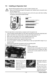
... x16 Slot (PCIEX16_1/PCIEX16_2) PCI Express x16 Slot (PCIEX8_1/PCIEX8_2) PCI Slot Follow the steps below to install an expansion card: • Make sure the motherboard supports the expansion card. 1-6 Installing an Expansion Card Read the following guidelines before installing an expansion card to release the card and then pull the...
... x16 Slot (PCIEX16_1/PCIEX16_2) PCI Express x16 Slot (PCIEX8_1/PCIEX8_2) PCI Slot Follow the steps below to install an expansion card: • Make sure the motherboard supports the expansion card. 1-6 Installing an Expansion Card Read the following guidelines before installing an expansion card to release the card and then pull the...
Manual
Page 20
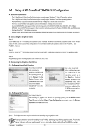
A CrossFireX/SLI-supported motherboard with your graphics cards for the power requirement) B. Browse to the CrossFireX menu and ensure the Enable CrossFireX™ check box is enabled. (Note) The ...
A CrossFireX/SLI-supported motherboard with your graphics cards for the power requirement) B. Browse to the CrossFireX menu and ensure the Enable CrossFireX™ check box is enabled. (Note) The ...

Manual
Page 21
... the internal SATA port(s) to the chassis back panel. • Turn off the power of the SATA signal cable and SATA power cable to your motherboard. Step 3: Connect the power cable from the bracket to the SATA port on the power supply before installing or removing the SATA bracket and SATA...
... the internal SATA port(s) to the chassis back panel. • Turn off the power of the SATA signal cable and SATA power cable to your motherboard. Step 3: Connect the power cable from the bracket to the SATA port on the power supply before installing or removing the SATA bracket and SATA...

Manual
Page 22
... 2.0/1.1 specification. Do not rock it side to side to a back panel connector, first remove the cable from your device and then remove it from the motherboard. • When removing the cable, pull it straight out from the connector. Connection/ Speed LED Activity LED LAN Port Connection/Speed LED: State Description Orange...
... 2.0/1.1 specification. Do not rock it side to side to a back panel connector, first remove the cable from your device and then remove it from the motherboard. • When removing the cable, pull it straight out from the connector. Connection/ Speed LED Activity LED LAN Port Connection/Speed LED: State Description Orange...


