
Manual
Page 1
... exists, users also can use X.H.D to easily add a hard drive into a RAID 0 array that before you can go to the Application Software screen to expand its capacity. Step 2: Install the RAID driver and operating system The X.H.D utility supports Windows 7/Vista/XP. Or you 'll not be recognized during the Windows setup process. (For more details, refer to enable RAID for complex and time-consuming configurations. To manually set eXtreme Hard Drive (X.H.D) under...
... exists, users also can use X.H.D to easily add a hard drive into a RAID 0 array that before you can go to the Application Software screen to expand its capacity. Step 2: Install the RAID driver and operating system The X.H.D utility supports Windows 7/Vista/XP. Or you 'll not be recognized during the Windows setup process. (For more details, refer to enable RAID for complex and time-consuming configurations. To manually set eXtreme Hard Drive (X.H.D) under...
Manual
Page 3
... 1.0. Disclaimer Information in the use GIGABYTE's unique features, read the Quick Installation Guide included with the product. For example, "REV: 1.0" means the revision of the product, read or download the information on/from the Support&Downloads\Motherboard\Technology Guide page on your motherboard revision before updating motherboard BIOS, drivers, or when looking for technical information. All rights reserved. No part of this manual may be reproduced, copied...
... 1.0. Disclaimer Information in the use GIGABYTE's unique features, read the Quick Installation Guide included with the product. For example, "REV: 1.0" means the revision of the product, read or download the information on/from the Support&Downloads\Motherboard\Technology Guide page on your motherboard revision before updating motherboard BIOS, drivers, or when looking for technical information. All rights reserved. No part of this manual may be reproduced, copied...
Manual
Page 4
... Expansion Card 19 1-7 Setup of ATI CrossFireX™/NVIDIA SLI Configuration 20 1-8 Installing the SATA Bracket 21 1-9 Back Panel Connectors 22 1-10 Onboard LEDs and Buttons 24 1-11 Internal Connectors 26 Chapter 2 BIOS Setup 37 2-1 Startup Screen 38 2-2 The Main Menu 39 2-3 MB Intelligent Tweaker(M.I.T 41 2-4 Standard CMOS Features 50 2-5 Advanced BIOS Features 52 2-6 Integrated Peripherals 54 2-7 Power Management Setup 58 2-8 PC Health Status 60 2-9 Load Fail-Safe Defaults 62 2-10 Load Optimized Defaults 62 2-11 Set Supervisor/User Password...
... Expansion Card 19 1-7 Setup of ATI CrossFireX™/NVIDIA SLI Configuration 20 1-8 Installing the SATA Bracket 21 1-9 Back Panel Connectors 22 1-10 Onboard LEDs and Buttons 24 1-11 Internal Connectors 26 Chapter 2 BIOS Setup 37 2-1 Startup Screen 38 2-2 The Main Menu 39 2-3 MB Intelligent Tweaker(M.I.T 41 2-4 Standard CMOS Features 50 2-5 Advanced BIOS Features 52 2-6 Integrated Peripherals 54 2-7 Power Management Setup 58 2-8 PC Health Status 60 2-9 Load Fail-Safe Defaults 62 2-10 Load Optimized Defaults 62 2-11 Set Supervisor/User Password...
Manual
Page 10
... PCI slots Multi-Graphics Support for 2-Way/3-Way ATI CrossFireX™/NVIDIA SLI technology Technology Storage Interface Chipset: - 6 x SATA 3Gb/s connectors (SATA2_0, SATA2_1, SATA2_2, SATA2_3, SATA2_4, SATA2_5) supporting up to GIGABYTE's website for the latest memory support list.) Audio Realtek ALC889 codec High Definition Audio 2/4/5.1/7.1-channel Support for Dolby® Home Theater Support for S/PDIF In/Out Support for CD In LAN 2 x Realtek RTL8111D chips...
... PCI slots Multi-Graphics Support for 2-Way/3-Way ATI CrossFireX™/NVIDIA SLI technology Technology Storage Interface Chipset: - 6 x SATA 3Gb/s connectors (SATA2_0, SATA2_1, SATA2_2, SATA2_3, SATA2_4, SATA2_5) supporting up to GIGABYTE's website for the latest memory support list.) Audio Realtek ALC889 codec High Definition Audio 2/4/5.1/7.1-channel Support for Dolby® Home Theater Support for S/PDIF In/Out Support for CD In LAN 2 x Realtek RTL8111D chips...
Manual
Page 20
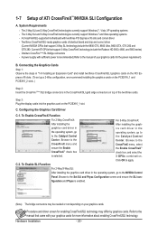
... Control Center. To Enable SLI Function For 2-Way/3-Way SLI: After installing the graphics card driver in the CrossFireX/SLI gold edge connectors on your graphics cards for more information about enabling CrossFireX/SLI technology. Step 3: Plug the display cable into the graphics card on the PCIEX16_1 slot. A CrossFireX/SLI-supported motherboard with sufficient power is selected. A power supply with two/three PCI Express x16 slots and correct driver - Configuring the Graphics Card Driver C-1. 1-7 Setup of your graphics cards. One/two CrossFire (Note)/SLI...
... Control Center. To Enable SLI Function For 2-Way/3-Way SLI: After installing the graphics card driver in the CrossFireX/SLI gold edge connectors on your graphics cards for more information about enabling CrossFireX/SLI technology. Step 3: Plug the display cable into the graphics card on the PCIEX16_1 slot. A CrossFireX/SLI-supported motherboard with sufficient power is selected. A power supply with two/three PCI Express x16 slots and correct driver - Configuring the Graphics Card Driver C-1. 1-7 Setup of your graphics cards. One/two CrossFire (Note)/SLI...

Manual
Page 25
... LED The Phase LEDs indicate the CPU loading. Use the clearing CMOS button to factory defaults when needed. The power button and reset button allow users to quickly turn off or reset the computer in an open-case environment when they want to change hardware components or conduct hardware testing. The higher the CPU loading, the more details. - 25 - Refer to Chapter 2, "BIOS Setup," for more the number of lighted LEDs. To enable the PHASE LED display...
... LED The Phase LEDs indicate the CPU loading. Use the clearing CMOS button to factory defaults when needed. The power button and reset button allow users to quickly turn off or reset the computer in an open-case environment when they want to change hardware components or conduct hardware testing. The higher the CPU loading, the more details. - 25 - Refer to Chapter 2, "BIOS Setup," for more the number of lighted LEDs. To enable the PHASE LED display...

Manual
Page 42
..., a CPU power-saving function in system halt state. When enabled, the CPU core frequency and voltage will be reduced during system halt state to alter the clock ratio for operating systems that supports this setting. (Default: Auto) CPU Cores Enabled (Note) Allows you to determine whether to enable all CPU cores. (Default) 1 Enables only one CPU core. 2 Enables only two CPU cores. 3 Enables only three CPU cores. CPU Frequency Displays the current operating CPU frequency. Advanced CPU Core Features CMOS Setup Utility-Copyright (C) 1984-2009 Award Software Advanced CPU...
..., a CPU power-saving function in system halt state. When enabled, the CPU core frequency and voltage will be reduced during system halt state to alter the clock ratio for operating systems that supports this setting. (Default: Auto) CPU Cores Enabled (Note) Allows you to determine whether to enable all CPU cores. (Default) 1 Enables only one CPU core. 2 Enables only two CPU cores. 3 Enables only three CPU cores. CPU Frequency Displays the current operating CPU frequency. Advanced CPU Core Features CMOS Setup Utility-Copyright (C) 1984-2009 Award Software Advanced CPU...

Manual
Page 43
.... Auto lets the BIOS automatically configure this setting. (Default: Auto) CPU EIST Function (Note) Enables or disables Enhanced Intel SpeedStep Technology (EIST). QPI Link Speed Displays the current operating QPI link speed. Important: It is highly recommended that supports this setting. (Default) When the CPU or chipset detects that an overheating is occurring, PROCHOT signals will allow for automated system reboot, or clear the CMOS values to reset the board to default values. (Default: Disabled) BCLK Frequency...
.... Auto lets the BIOS automatically configure this setting. (Default: Auto) CPU EIST Function (Note) Enables or disables Enhanced Intel SpeedStep Technology (EIST). QPI Link Speed Displays the current operating QPI link speed. Important: It is highly recommended that supports this setting. (Default) When the CPU or chipset detects that an overheating is occurring, PROCHOT signals will allow for automated system reboot, or clear the CMOS values to reset the board to default values. (Default: Disabled) BCLK Frequency...
Manual
Page 49
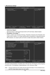
... virtual systems. (Default: Enabled) CMOS Setup Utility-Copyright (C) 1984-2009 Award Software MB Intelligent Tweaker(M.I.T.) } M.I.T Current Status } Advanced Frequency Settings } Advanced Memory Settings } Advanced Voltage Settings } Miscellaneous Settings [Press Enter] [Press Enter] [Press Enter] [Press Enter] [Press Enter] Item Help Menu Level BIOS Version BCLK CPU Frequency Memory Frequency Total Memory Size D25 133.27 MHz 3198.42 MHz 1332.80 MHz 1024 MB CPU Temperature PCH Temperature 45oC 40oC Vcore DRAM Voltage...
... virtual systems. (Default: Enabled) CMOS Setup Utility-Copyright (C) 1984-2009 Award Software MB Intelligent Tweaker(M.I.T.) } M.I.T Current Status } Advanced Frequency Settings } Advanced Memory Settings } Advanced Voltage Settings } Miscellaneous Settings [Press Enter] [Press Enter] [Press Enter] [Press Enter] [Press Enter] Item Help Menu Level BIOS Version BCLK CPU Frequency Memory Frequency Total Memory Size D25 133.27 MHz 3198.42 MHz 1332.80 MHz 1024 MB CPU Temperature PCH Temperature 45oC 40oC Vcore DRAM Voltage...

Manual
Page 52
... CPUID Max. Quick Boot Enables or disables the quick boot function to accept. Setup A password is only required for daily use. Use the up or down arrow key to select a device and press to speed up the system boot-up or down on the list. Options are: Floppy, LS120, Hard Disk, CDROM, ZIP, USB-FDD, USB-ZIP, USB-CDROM, USB-HDD, Legacy LAN, Disabled. 2-5 Advanced BIOS Features CMOS Setup Utility-Copyright (C) 1984-2009 Award Software Advanced BIOS Features } Hard Disk Boot Priority Quick Boot First Boot Device Second Boot Device Third Boot Device Password...
... CPUID Max. Quick Boot Enables or disables the quick boot function to accept. Setup A password is only required for daily use. Use the up or down arrow key to select a device and press to speed up the system boot-up or down on the list. Options are: Floppy, LS120, Hard Disk, CDROM, ZIP, USB-FDD, USB-ZIP, USB-CDROM, USB-HDD, Legacy LAN, Disabled. 2-5 Advanced BIOS Features CMOS Setup Utility-Copyright (C) 1984-2009 Award Software Advanced BIOS Features } Hard Disk Boot Priority Quick Boot First Boot Device Second Boot Device Third Boot Device Password...

Manual
Page 54
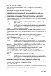
... (Default: Disabled) PCH SATA Control Mode (Intel P55 Chipset) Enables or disables RAID for the SATA controllers. BIOS Setup - 54 - 2-6 Integrated Peripherals CMOS Setup Utility-Copyright (C) 1984-2009 Award Software Integrated Peripherals eXtreme Hard Drive (XHD) PCH SATA Control Mode SATA Port0-3 Native Mode USB Controllers USB Legacy Function USB Storage Function SLI/CF Ultra Performance Azalia Codec Onboard H/W 1394 Onboard H/W LAN1 Onboard H/W LAN2 Green LAN } SMART LAN1 } SMART LAN2 Onboard LAN1 Boot ROM Onboard LAN2 Boot ROM...
... (Default: Disabled) PCH SATA Control Mode (Intel P55 Chipset) Enables or disables RAID for the SATA controllers. BIOS Setup - 54 - 2-6 Integrated Peripherals CMOS Setup Utility-Copyright (C) 1984-2009 Award Software Integrated Peripherals eXtreme Hard Drive (XHD) PCH SATA Control Mode SATA Port0-3 Native Mode USB Controllers USB Legacy Function USB Storage Function SLI/CF Ultra Performance Azalia Codec Onboard H/W 1394 Onboard H/W LAN1 Onboard H/W LAN2 Green LAN } SMART LAN1 } SMART LAN2 Onboard LAN1 Boot ROM Onboard LAN2 Boot ROM...
Manual
Page 57
... boot ROM integrated with the onboard LAN chip. (Default: Disabled) Onboard USB 3.0 Controller (NEC USB 3.0 Controller) Enables or disables the USB 3.0 controller integrated in the NEC chip. (Default: Enabled) eSATA Controller (JMicron JMB362 Chip, eSATA Connectors on the Back Panel) Enables or disables the SATA controller integrated in the JMicron JMB362 chip. (Default: Enabled) eSATA Ctrl Mode (JMicron JMB362 Chip, eSATA Connectors on configuring a RAID array. IDE Configures the SATA controller to IDE mode. (Default) AHCI Configures the SATA controller to AHCI mode. IDE Disables...
... boot ROM integrated with the onboard LAN chip. (Default: Disabled) Onboard USB 3.0 Controller (NEC USB 3.0 Controller) Enables or disables the USB 3.0 controller integrated in the NEC chip. (Default: Enabled) eSATA Controller (JMicron JMB362 Chip, eSATA Connectors on the Back Panel) Enables or disables the SATA controller integrated in the JMicron JMB362 chip. (Default: Enabled) eSATA Ctrl Mode (JMicron JMB362 Chip, eSATA Connectors on configuring a RAID array. IDE Configures the SATA controller to IDE mode. (Default) AHCI Configures the SATA controller to AHCI mode. IDE Disables...

Manual
Page 58
... (default). 2-7 Power Management Setup CMOS Setup Utility-Copyright (C) 1984-2009 Award Software Power Management Setup ACPI Suspend Type ACPI LED Control Soft-Off by PWR-BTTN PME Event Wake Up Power On by Ring Resume by Alarm x Date (of Month) Alarm x Time (hh:mm:ss) Alarm HPET Support (Note) HPET Mode (Note) Power On By Mouse Power On By Keyboard x KB Power ON Password AC Back Function EuP Support [S3(STR)] [Enabled] [Instant-Off] [Enabled] [Enabled] [Disabled] Everyday 0 : 0 : 0 [Enabled] [32-bit mode] [Disabled] [Disabled] Enter...
... (default). 2-7 Power Management Setup CMOS Setup Utility-Copyright (C) 1984-2009 Award Software Power Management Setup ACPI Suspend Type ACPI LED Control Soft-Off by PWR-BTTN PME Event Wake Up Power On by Ring Resume by Alarm x Date (of Month) Alarm x Time (hh:mm:ss) Alarm HPET Support (Note) HPET Mode (Note) Power On By Mouse Power On By Keyboard x KB Power ON Password AC Back Function EuP Support [S3(STR)] [Enabled] [Instant-Off] [Enabled] [Enabled] [Disabled] Everyday 0 : 0 : 0 [Enabled] [32-bit mode] [Disabled] [Disabled] Enter...
Manual
Page 84
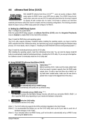
... load the SATA controller driver first. Before installing the operating system, you have to enable RAID for the Intel SATA controllers. To automatically set up a RAID 0 array: Click Auto to automatically set up a RAID-ready system and configure it for RAID 0. Exits the X.H.D utility: Click Cancel to exit the X.H.D utility. (Note 1) The X.H.D utility only supports the SATA controllers integrated in the array. ) 1. For a RAID 0 array that already exists, users also can use X.H.D to easily add a hard drive...
... load the SATA controller driver first. Before installing the operating system, you have to enable RAID for the Intel SATA controllers. To automatically set up a RAID 0 array: Click Auto to automatically set up a RAID-ready system and configure it for RAID 0. Exits the X.H.D utility: Click Cancel to exit the X.H.D utility. (Note 1) The X.H.D utility only supports the SATA controllers integrated in the array. ) 1. For a RAID 0 array that already exists, users also can use X.H.D to easily add a hard drive...
Manual
Page 101
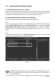
... Award Software Integrated Peripherals eSATA Controller eSATA Ctrl Mode GSATA 6_7/IDE Controller GSATA 6_7/IDE Ctrl Mode GSATA 8_9/IDE Controller GSATA 8_9/IDE Ctrl Mode GSATA RAID Configuration Onboard Serial Port 1 [Enabled] [IDE] [Enabled] [IDE] [Enabled] [IDE] [Press Enter] [3F8/IRQ4] Item Help Menu Level Move Enter: Select F5: Previous Values +/-/PU/PD: Value F10: Save F6: Fail-Safe Defaults Figure 1 ESC: Exit F1: General Help F7: Optimized Defaults The BIOS Setup menus described in system BIOS Setup. Then connect the power connector...
... Award Software Integrated Peripherals eSATA Controller eSATA Ctrl Mode GSATA 6_7/IDE Controller GSATA 6_7/IDE Ctrl Mode GSATA 8_9/IDE Controller GSATA 8_9/IDE Ctrl Mode GSATA RAID Configuration Onboard Serial Port 1 [Enabled] [IDE] [Enabled] [IDE] [Enabled] [IDE] [Press Enter] [3F8/IRQ4] Item Help Menu Level Move Enter: Select F5: Previous Values +/-/PU/PD: Value F10: Save F6: Fail-Safe Defaults Figure 1 ESC: Exit F1: General Help F7: Optimized Defaults The BIOS Setup menus described in system BIOS Setup. Then connect the power connector...

Manual
Page 106
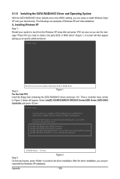
For installing Windows Vista, you need to install the SATA controller driver during the Windows setup process. Steps: 1: Boot from the motherboard driver disk to a floppy disk. sume that the drive letter for AHCI and RAID Mode) To successfully install operating system onto SATA hard drive(s) that has CD-ROM support and a blank formatted floppy disk. Appendix - 106 - 5-1-4 Making a SATA RAID/AHCI Driver Diskette (Required for your optical drive is /are configured to RAID/AHCI mode, you also can copy the SATA controller driver from the motherboard driver disk to a USB flash drive....
For installing Windows Vista, you need to install the SATA controller driver during the Windows setup process. Steps: 1: Boot from the motherboard driver disk to a floppy disk. sume that the drive letter for AHCI and RAID Mode) To successfully install operating system onto SATA hard drive(s) that has CD-ROM support and a blank formatted floppy disk. Appendix - 106 - 5-1-4 Making a SATA RAID/AHCI Driver Diskette (Required for your optical drive is /are configured to RAID/AHCI mode, you also can copy the SATA controller driver from the motherboard driver disk to a USB flash drive....
Manual
Page 108
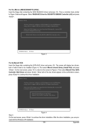
... SATA RAID Controller Intel(R) ICH8M-E/ICH9M-E/5 Series SATA RAID Controller ENTER=Select F3=Exit Figure 2 Step 3: On the next screen, press to configure a SCSI Adapter for use with the Windows XP installation. 5-1-5 Installing the SATA RAID/AHCI Driver and Operating System With the SATA RAID/AHCI driver diskette and correct BIOS settings, you need to install a 3rd party SCSI or RAID driver" (Figure 1). The followings are ready to install Windows Vista/ XP onto your system to boot from the Windows XP setup disk...
... SATA RAID Controller Intel(R) ICH8M-E/ICH9M-E/5 Series SATA RAID Controller ENTER=Select F3=Exit Figure 2 Step 3: On the next screen, press to configure a SCSI Adapter for use with the Windows XP installation. 5-1-5 Installing the SATA RAID/AHCI Driver and Operating System With the SATA RAID/AHCI driver diskette and correct BIOS settings, you need to install a 3rd party SCSI or RAID driver" (Figure 1). The followings are ready to install Windows Vista/ XP onto your system to boot from the Windows XP setup disk...
Manual
Page 109
... the driver installation, you can proceed with Windows, using a device support disk provided by an adapter manufacturer. Then select Marvell 91xx SATA Controller 32bit Driver and press . Windows Setup You have chosen to be installed (Figure 4). Windows Setup You have chosen to the previous screen. Then a controller menu similar to Figure 3 below will display two drivers, both of which need to configure a SCSI Adapter for use with the Windows XP installation. - 109 - RAID/AHCI Driver for GIGABYTE GBB36X Controller...
... the driver installation, you can proceed with Windows, using a device support disk provided by an adapter manufacturer. Then select Marvell 91xx SATA Controller 32bit Driver and press . Windows Setup You have chosen to be installed (Figure 4). Windows Setup You have chosen to the previous screen. Then a controller menu similar to Figure 3 below will display two drivers, both of which need to configure a SCSI Adapter for use with the Windows XP installation. - 109 - RAID/AHCI Driver for GIGABYTE GBB36X Controller...

Manual
Page 129
.... A: The following Award BIOS beep code descriptions may help you identify possible computer problems. (For reference only.) 1 short: System boots successfully 1 long, 3 short: Keyboard error 2 short: CMOS setting error 1 long, 9 short: BIOS ROM error 1 long, 1 short: Memory or motherboard error Continuous long beeps: Graphics card not inserted properly 1 long, 2 short: Monitor or graphics card error Continuous short beeps: Power error - 129 - Appendix Press to enter BIOS Setup during the POST mean? In the Main Menu, press + to the CMOS, which will clear the CMOS values after the...
.... A: The following Award BIOS beep code descriptions may help you identify possible computer problems. (For reference only.) 1 short: System boots successfully 1 long, 3 short: Keyboard error 2 short: CMOS setting error 1 long, 9 short: BIOS ROM error 1 long, 1 short: Memory or motherboard error Continuous long beeps: Graphics card not inserted properly 1 long, 2 short: Monitor or graphics card error Continuous short beeps: Power error - 129 - Appendix Press to enter BIOS Setup during the POST mean? In the Main Menu, press + to the CMOS, which will clear the CMOS values after the...

Manual
Page 134
... CMOS setup 2. If password is supported - Set up floppy related fields in Setup & Auto-configuration table 1. APM initialization Clear noise of the memory 1. Assign resources to CMOS Initialize ISA PnP boot devices 1. Auto assign ports to onboard COM ports if the corresponding item in stack back to all data in Setup is pressed to enter Setup utility; Detect serial ports & parallel ports Detect & install co-processor Init HDD write protect 1. Clear EPA or customization logo 1. Enable/Disable Parity Check according to "AUTO" 1. Switch screen...
... CMOS setup 2. If password is supported - Set up floppy related fields in Setup & Auto-configuration table 1. APM initialization Clear noise of the memory 1. Assign resources to CMOS Initialize ISA PnP boot devices 1. Auto assign ports to onboard COM ports if the corresponding item in stack back to all data in Setup is pressed to enter Setup utility; Detect serial ports & parallel ports Detect & install co-processor Init HDD write protect 1. Clear EPA or customization logo 1. Enable/Disable Parity Check according to "AUTO" 1. Switch screen...


