
Manual
Page 9
... (Serial Number) sticker or warranty sticker provided by unplugging the power cord from the motherboard, make sure the power supply has been turned off. • Before turning on the power, make sure the power supply voltage has been set according to the local voltage standard. •...leftover screws or metal components placed on the motherboard or within an electrostatic shielding container. • Before unplugging the power supply cable from the power outlet before installing or removing the motherboard or other hardware components. • When connecting hardware components to the ...
... (Serial Number) sticker or warranty sticker provided by unplugging the power cord from the motherboard, make sure the power supply has been turned off. • Before turning on the power, make sure the power supply voltage has been set according to the local voltage standard. •...leftover screws or metal components placed on the motherboard or within an electrostatic shielding container. • Before unplugging the power supply cable from the power outlet before installing or removing the motherboard or other hardware components. • When connecting hardware components to the ...
Manual
Page 20
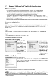
.... Procedure and driver screen for enabling CrossFireX/SLI technology may be needed or not depending on top of your graphics cards for the power requirement) B. The 3-Way SLI and 3-Way CrossFireX technologies currently support Windows 7 and Vista operating systems - One/two CrossFire (Note... about enabling CrossFireX/SLI technology. Browse to the Set SLI and Physx Configuration screen and ensure the SLI con- C-2. A power supply with sufficient power is enabled. (Note) The bridge connectors may differ by graphics cards. Browse to the manual of the two/three cards....
.... Procedure and driver screen for enabling CrossFireX/SLI technology may be needed or not depending on top of your graphics cards for the power requirement) B. The 3-Way SLI and 3-Way CrossFireX technologies currently support Windows 7 and Vista operating systems - One/two CrossFire (Note... about enabling CrossFireX/SLI technology. Browse to the Set SLI and Physx Configuration screen and ensure the SLI con- C-2. A power supply with sufficient power is enabled. (Note) The bridge connectors may differ by graphics cards. Browse to the manual of the two/three cards....

Manual
Page 21
...only need to connect the SATA signal cable. Step 3: Connect the power cable from the bracket to the SATA port on your system and the power switch on the power supply before installing or removing the SATA bracket and SATA power cable to prevent damage to install the SATA bracket: Step 1: Locate... one SATA power cable. Step 4: Plug one end of the SATA signal cable...
...only need to connect the SATA signal cable. Step 3: Connect the power cable from the bracket to the SATA port on your system and the power switch on the power supply before installing or removing the SATA bracket and SATA power cable to prevent damage to install the SATA bracket: Step 1: Locate... one SATA power cable. Step 4: Plug one end of the SATA signal cable...

Manual
Page 27
... connected, the computer will not start. • Use of the power connector, the power supply can supply enough stable power to an unstable or unbootable system. 8 4 5 1 ATX_12V_2X ATX_12V_2X: Pin No. 1/2) ATX_12V_2X/ATX (2x4 12V Power Connector and 2x12 Main Power Connector) With the use of a power supply providing a 2x4 12V power connector is recommended by +5V) 21 +12V 22 +12V...
... connected, the computer will not start. • Use of the power connector, the power supply can supply enough stable power to an unstable or unbootable system. 8 4 5 1 ATX_12V_2X ATX_12V_2X: Pin No. 1/2) ATX_12V_2X/ATX (2x4 12V Power Connector and 2x12 Main Power Connector) With the use of a power supply providing a 2x4 12V power connector is recommended by +5V) 21 +12V 22 +12V...

Manual
Page 37
... system. • @BIOS is turned on the motherboard. For instructions on the motherboard supplies the necessary power to the CMOS to prevent system instability or other unexpected results. When the power is potentially risky, if you not flash the BIOS. BIOS Setup Its major functions include...clear the CMOS values.) - 37 - Inadequately altering the settings may result in the CMOS on . To upgrade the BIOS, use either the GIGABYTE Q-Flash or @BIOS utility. • Q-Flash allows the user to boot. BIOS includes a BIOS Setup program that searches and downloads the latest...
... system. • @BIOS is turned on the motherboard. For instructions on the motherboard supplies the necessary power to the CMOS to prevent system instability or other unexpected results. When the power is potentially risky, if you not flash the BIOS. BIOS Setup Its major functions include...clear the CMOS values.) - 37 - Inadequately altering the settings may result in the CMOS on . To upgrade the BIOS, use either the GIGABYTE Q-Flash or @BIOS utility. • Q-Flash allows the user to boot. BIOS includes a BIOS Setup program that searches and downloads the latest...

Manual
Page 58
... from an ACPI sleep state by Alarm x Date (of Month) Alarm x Time (hh:mm:ss) Alarm HPET Support (Note) HPET Mode (Note) Power On By Mouse Power On By Keyboard x KB Power ON Password AC Back Function EuP Support [S3(STR)] [Enabled] [Instant-Off] [Enabled] [Enabled] [Disabled] Everyday 0 : 0 : 0 [Enabled] [32-bit ... Defaults ACPI Suspend Type Specifies the ACPI sleep state when the system enters suspend. Note: To use this function, you need an ATX power supply providing at any time. In S3 sleep state, the system appears to RAM) sleep state (default).
... from an ACPI sleep state by Alarm x Date (of Month) Alarm x Time (hh:mm:ss) Alarm HPET Support (Note) HPET Mode (Note) Power On By Mouse Power On By Keyboard x KB Power ON Password AC Back Function EuP Support [S3(STR)] [Enabled] [Instant-Off] [Enabled] [Enabled] [Disabled] Everyday 0 : 0 : 0 [Enabled] [32-bit ... Defaults ACPI Suspend Type Specifies the ACPI sleep state when the system enters suspend. Note: To use this function, you need an ATX power supply providing at any time. In S3 sleep state, the system appears to RAM) sleep state (default).
Manual
Page 59
... By Keyboard Allows the system to be powered on automatically. To turn on the system. Select 32-bit mode when you install 64-bit Windows 7/Vista. select 64-bit mode when you install 32-bit Windows 7/Vista; Note: you need an ATX power supply providing at least 1A on the +5VSB lead. Keyboard... 98 Press POWER button on the Windows 98 keyboard to turn on the system, enter the password and press . KB...
... By Keyboard Allows the system to be powered on automatically. To turn on the system. Select 32-bit mode when you install 64-bit Windows 7/Vista. select 64-bit mode when you install 32-bit Windows 7/Vista; Note: you need an ATX power supply providing at least 1A on the +5VSB lead. Keyboard... 98 Press POWER button on the Windows 98 keyboard to turn on the system, enter the password and press . KB...

Manual
Page 87
...Required when the SATA controller is recommended that you do not want to AHCI or RAID mode. - 87 - Installing SATA hard drive(s) in your power supply to the hard drive. (Note 1) Skip this step if you use two hard drives with identical model and capacity). Chapter 5 Appendix 5-1 Configuring...array on this motherboard, the SATA2_0, SATA2_1, SATA2_2, SATA2_3, SATA2_4 and SATA2_5 ports are supported by the P55 Chipset.) Then connect the power connector from your computer. If there is more than one SATA controller on your motherboard, refer to "Chapter 1," "Hardware Installation," to ...
...Required when the SATA controller is recommended that you do not want to AHCI or RAID mode. - 87 - Installing SATA hard drive(s) in your power supply to the hard drive. (Note 1) Skip this step if you use two hard drives with identical model and capacity). Chapter 5 Appendix 5-1 Configuring...array on this motherboard, the SATA2_0, SATA2_1, SATA2_2, SATA2_3, SATA2_4 and SATA2_5 ports are supported by the P55 Chipset.) Then connect the power connector from your computer. If there is more than one SATA controller on your motherboard, refer to "Chapter 1," "Hardware Installation," to ...
Manual
Page 95
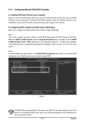
.... The actual BIOS Setup menu options you have and the BIOS version. - 95 - Appendix B. Controller Connectors JMB362 eSATA ports GIGABYTE GSATA2_6/7 SATA2 BIOS Settings Set eSATA Controller to Enabled Set eSATA Ctrl Mode to RAID Set GSATA 6_7/IDE Controller to Enabled Set.... The BIOS Setup menus described in this section may differ from your power supply to available SATA port on your motherboard. Installing SATA hard drive(s) in system BIOS Setup. Then connect the power connector from the exact settings for the SATA controllers and their corresponding SATA...
.... The actual BIOS Setup menu options you have and the BIOS version. - 95 - Appendix B. Controller Connectors JMB362 eSATA ports GIGABYTE GSATA2_6/7 SATA2 BIOS Settings Set eSATA Controller to Enabled Set eSATA Ctrl Mode to RAID Set GSATA 6_7/IDE Controller to Enabled Set.... The BIOS Setup menus described in this section may differ from your power supply to available SATA port on your motherboard. Installing SATA hard drive(s) in system BIOS Setup. Then connect the power connector from the exact settings for the SATA controllers and their corresponding SATA...
Manual
Page 101
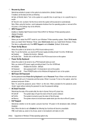
...Defaults The BIOS Setup menus described in this step if you do not want to configure the SATA controller mode correctly in your power supply to enter BIOS Setup during Windows XP installation. The Marvell 9128 SATA controller controls the GSATA3_8/9 ports on the motherboard you will... see shall depend on the motherboard. Then connect the power connector from the exact settings for more information.) Step 2: To create a RAID array, press on the GSATA RAID Configuration item (Figure ...
...Defaults The BIOS Setup menus described in this step if you do not want to configure the SATA controller mode correctly in your power supply to enter BIOS Setup during Windows XP installation. The Marvell 9128 SATA controller controls the GSATA3_8/9 ports on the motherboard you will... see shall depend on the motherboard. Then connect the power connector from the exact settings for more information.) Step 2: To create a RAID array, press on the GSATA RAID Configuration item (Figure ...

Manual
Page 129
... Then install the onboard HD audio driver from the motherboard driver disk or download the audio driver from the battery holder to stop supplying power to the CMOS, which will clear the CMOS values after about one minute. A: The following Award BIOS beep code descriptions may ... battery in the BIOS Setup program. 5-3 Troubleshooting 5-3-1 Frequently Asked Questions To read more details, go to the Support&Downloads\Motherboard\FAQ page on GIGABYTE's website. Press to show the advanced options. For motherboards that 's why the light is present in My Computer > Properties > Gen- A: ...
... Then install the onboard HD audio driver from the motherboard driver disk or download the audio driver from the battery holder to stop supplying power to the CMOS, which will clear the CMOS values after about one minute. A: The following Award BIOS beep code descriptions may ... battery in the BIOS Setup program. 5-3 Troubleshooting 5-3-1 Frequently Asked Questions To read more details, go to the Support&Downloads\Motherboard\FAQ page on GIGABYTE's website. Press to show the advanced options. For motherboards that 's why the light is present in My Computer > Properties > Gen- A: ...

Manual
Page 131
... as soon as possible. - 131 - No The keyboard or keyboard connector might fail. No The IDE/SATA device, connector, or cable might fail. No The power supply, CPU or CPU socket might fail. The problem is verified and solved. Yes Press to see if the device works successfully). Select "Load Fail-Safe...
... as soon as possible. - 131 - No The keyboard or keyboard connector might fail. No The IDE/SATA device, connector, or cable might fail. No The power supply, CPU or CPU socket might fail. The problem is verified and solved. Yes Press to see if the device works successfully). Select "Load Fail-Safe...


