
Manual
Page 25
... to BIOS Setup to load factory defaults (select Load Optimized Defaults) or manually configure the BIOS settings (refer to change hardware components or conduct hardware testing. Quick Buttons This motherboard has 3 quick buttons: power button, reset button and clearing CMOS button.
... to BIOS Setup to load factory defaults (select Load Optimized Defaults) or manually configure the BIOS settings (refer to change hardware components or conduct hardware testing. Quick Buttons This motherboard has 3 quick buttons: power button, reset button and clearing CMOS button.

Manual
Page 37
... CMOS on . Refer to Chapter 5, "Troubleshooting," for how to prevent system instability or other unexpected results. To upgrade the BIOS, use either the GIGABYTE Q-Flash or @BIOS utility. • Q-Flash allows the user to quickly and easily upgrade or back up BIOS without entering the operating system. ... parameters and loading operating system, etc. Inadequate BIOS flashing may result in the CMOS. Its major functions include conducting the Power-On Self-Test (POST) during the POST. When the power is turned off, the battery on using the Q-Flash and @BIOS utilities, refer to activate...
... CMOS on . Refer to Chapter 5, "Troubleshooting," for how to prevent system instability or other unexpected results. To upgrade the BIOS, use either the GIGABYTE Q-Flash or @BIOS utility. • Q-Flash allows the user to quickly and easily upgrade or back up BIOS without entering the operating system. ... parameters and loading operating system, etc. Inadequate BIOS flashing may result in the CMOS. Its major functions include conducting the Power-On Self-Test (POST) during the POST. When the power is turned off, the battery on using the Q-Flash and @BIOS utilities, refer to activate...

Manual
Page 77
Actual results may vary depending on testing method. - 77 - Button Information Table Button Description 1 Dynamic Energy Saver On/Off Switch (Default: Off) 2 Current CPU Power Consumption 3 Power Saving (Calculate power savings ...) 13 Minimize (Application will continue to provide exceptional power savings and enhanced power efficiency without sacrificing computing performance. Unique Features Meter Mode In Meter Mode, GIGABYTE Dynamic Energy SaverTM 2 shows how much power they have saved in taskbar) 14 INFO/Help 15 Motherboard Phase LED On/Off Switch (Default: On)...
Actual results may vary depending on testing method. - 77 - Button Information Table Button Description 1 Dynamic Energy Saver On/Off Switch (Default: Off) 2 Current CPU Power Consumption 3 Power Saving (Calculate power savings ...) 13 Minimize (Application will continue to provide exceptional power savings and enhanced power efficiency without sacrificing computing performance. Unique Features Meter Mode In Meter Mode, GIGABYTE Dynamic Energy SaverTM 2 shows how much power they have saved in taskbar) 14 INFO/Help 15 Motherboard Phase LED On/Off Switch (Default: On)...

Manual
Page 88
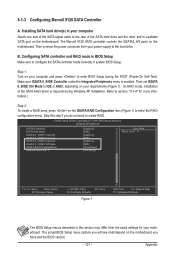
... correctly in this section may differ from the exact settings for your computer and press to enter BIOS Setup during the POST (Power-On Self-Test). Step 1: Turn on the motherboard you will be set eXtreme Hard Drive (XHD) under the Integrated Peripherals menu to Enabled (Figure 1) and PCH SATA Control...
... correctly in this section may differ from the exact settings for your computer and press to enter BIOS Setup during the POST (Power-On Self-Test). Step 1: Turn on the motherboard you will be set eXtreme Hard Drive (XHD) under the Integrated Peripherals menu to Enabled (Figure 1) and PCH SATA Control...

Manual
Page 89
... RAID Volumes : None defined. Intel(R) Rapid Storage Technology - Press + to Non-RAID 4. option ROM - 9.5.0.1037 Copyright(C) 2003-09 Intel Corporation. Step 1: After the POST memory test begins and before the operating system boot begins, look for a non-RAID configuration. C. Configuring a RAID array in MAIN MENU and press . Intel(R) Rapid Storage Technology...
... RAID Volumes : None defined. Intel(R) Rapid Storage Technology - Press + to Non-RAID 4. option ROM - 9.5.0.1037 Copyright(C) 2003-09 Intel Corporation. Step 1: After the POST memory test begins and before the operating system boot begins, look for a non-RAID configuration. C. Configuring a RAID array in MAIN MENU and press . Intel(R) Rapid Storage Technology...

Manual
Page 96
... installation of the RAID setup utility (Figure 3), use the up or down arrow key to highlight through choices in the Main Menu block. GIGABYTE Technology Corp. Figure 2 In the main screen of Windows operating system for a message which says "Press to configure a RAID array. Highlight... + to enter RAID Setup Utility ... Appendix - 96 - PCI Express to SATAII HOST Controller ROM v1.07.06 Copyright (C) 2005-2009 Gigabyte Technology Corp. (http://www.gigabyte.com) HDD0 : HDD1 : ST3120026AS ST3120026AS 120 GB 120 GB Non-RAID Non-RAID Press to enter the RAID setup utility...
... installation of the RAID setup utility (Figure 3), use the up or down arrow key to highlight through choices in the Main Menu block. GIGABYTE Technology Corp. Figure 2 In the main screen of Windows operating system for a message which says "Press to configure a RAID array. Highlight... + to enter RAID Setup Utility ... Appendix - 96 - PCI Express to SATAII HOST Controller ROM v1.07.06 Copyright (C) 2005-2009 Gigabyte Technology Corp. (http://www.gigabyte.com) HDD0 : HDD1 : ST3120026AS ST3120026AS 120 GB 120 GB Non-RAID Non-RAID Press to enter the RAID setup utility...
Manual
Page 101
... the SATA AHCI driver is enabled. Make sure GSATA 8_9/IDE Controller under the Integrated Peripherals menu is required during the POST (Power-On Self-Test). CMOS Setup Utility-Copyright (C) 1984-2009 Award Software Integrated Peripherals eSATA Controller eSATA Ctrl Mode GSATA 6_7/IDE Controller GSATA 6_7/IDE Ctrl Mode GSATA...
... the SATA AHCI driver is enabled. Make sure GSATA 8_9/IDE Controller under the Integrated Peripherals menu is required during the POST (Power-On Self-Test). CMOS Setup Utility-Copyright (C) 1984-2009 Award Software Integrated Peripherals eSATA Controller eSATA Ctrl Mode GSATA 6_7/IDE Controller GSATA 6_7/IDE Ctrl Mode GSATA...

Manual
Page 132
...by OEM customers Initial onboard clock generator if Early_Init_Onboard_Generator is defined. Disable PS/2 mouse interface (optional) 2. If test fails, keep beeping the speaker Auto detect flash type to E000 & F000 shadow RAM Expand the Xgroup codes... C3h C5h 01h 02h 03h 05h 07h 08h 0Ah 0Eh 10h 12h 14h 16h 18h 1Bh 1Dh 23h Description Test CMOS R/W functionality Early chipset initialization: -Disable shadow RAM - Program basic chipset registers Detect memory - Blank ...
...by OEM customers Initial onboard clock generator if Early_Init_Onboard_Generator is defined. Disable PS/2 mouse interface (optional) 2. If test fails, keep beeping the speaker Auto detect flash type to E000 & F000 shadow RAM Expand the Xgroup codes... C3h C5h 01h 02h 03h 05h 07h 08h 0Ah 0Eh 10h 12h 14h 16h 18h 1Bh 1Dh 23h Description Test CMOS R/W functionality Early chipset initialization: -Disable shadow RAM - Program basic chipset registers Detect memory - Blank ...

Manual
Page 133
...Clear password according to CMOS setup Example: onboard IDE controller 4. Program CPU internal MTRR for Pentium class CPU 3. Calculate total memory by testing the last double word of the ESCD's legacy information Early PCI initialization: - Appendix If ESCD is valid, take into C000:0 1. ... 1. Init onboard H/W monitor devices Initialize INT 09 buffer 1. See also POST 63h Test DMA Channel 0 Test DMA Channel 1 Test DMA page registers Test 8254 Test 8259 interrupt mask bits for channel 1 Test 8259 interrupt mask bits for P6 class CPU 4. Program MTRR of processors (multi-processor...
...Clear password according to CMOS setup Example: onboard IDE controller 4. Program CPU internal MTRR for Pentium class CPU 3. Calculate total memory by testing the last double word of the ESCD's legacy information Early PCI initialization: - Appendix If ESCD is valid, take into C000:0 1. ... 1. Init onboard H/W monitor devices Initialize INT 09 buffer 1. See also POST 63h Test DMA Channel 0 Test DMA Channel 1 Test DMA page registers Test 8254 Test 8259 interrupt mask bits for channel 1 Test 8259 interrupt mask bits for P6 class CPU 4. Program MTRR of processors (multi-processor...