
Manual
Page 1
... set eXtreme Hard Drive (X.H.D) under the Integrated Peripherals menu to Enabled to Chapter 5, "Installing the SATA RAID/AHCI Driver and Operating System." ) Step 3: Install the motherboard drivers and the X.H.D utiltiy After installing the operating system, insert the motherboard driver disk. Exits the X.H.D utility: Click Cancel to exit the X.H.D utility. (Note 1) The X.H.D utility only supports the SATA controllers integrated in the array. ) 1. eXtreme Hard Drive (X.H.D) With GIGABYTE eXtreme Hard Drive (X.H.D)(Note 1), users can quickly configure a RAIDready system for RAID...
... set eXtreme Hard Drive (X.H.D) under the Integrated Peripherals menu to Enabled to Chapter 5, "Installing the SATA RAID/AHCI Driver and Operating System." ) Step 3: Install the motherboard drivers and the X.H.D utiltiy After installing the operating system, insert the motherboard driver disk. Exits the X.H.D utility: Click Cancel to exit the X.H.D utility. (Note 1) The X.H.D utility only supports the SATA controllers integrated in the array. ) 1. eXtreme Hard Drive (X.H.D) With GIGABYTE eXtreme Hard Drive (X.H.D)(Note 1), users can quickly configure a RAIDready system for RAID...
Manual
Page 3
... in the use GIGABYTE's unique features, read or download the information on/from the Support&Downloads\Motherboard\Technology Guide page on your motherboard revision before updating motherboard BIOS, drivers, or when looking for technical information. For example, "REV: 1.0" means the revision of the motherboard is the property of GIGABYTE. Changes to use of this product, GIGABYTE provides the following types of documentations: For quick set-up of this manual is protected...
... in the use GIGABYTE's unique features, read or download the information on/from the Support&Downloads\Motherboard\Technology Guide page on your motherboard revision before updating motherboard BIOS, drivers, or when looking for technical information. For example, "REV: 1.0" means the revision of the motherboard is the property of GIGABYTE. Changes to use of this product, GIGABYTE provides the following types of documentations: For quick set-up of this manual is protected...
Manual
Page 4
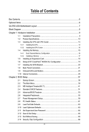
... 1-4-2 Installing a Memory 17 1-5 Installing an Expansion Card 18 1-6 Setup of ATI CrossFireX™/NVIDIA SLI Configuration 19 1-7 Installing the SATA Bracket 20 1-8 Back Panel Connectors 21 1-9 Onboard LEDs and Buttons 23 1-10 Internal Connectors 25 Chapter 2 BIOS Setup 37 2-1 Startup Screen 38 2-2 The Main Menu 39 2-3 MB Intelligent Tweaker(M.I.T 41 2-4 Standard CMOS Features 51 2-5 Advanced BIOS Features 53 2-6 Integrated Peripherals 55 2-7 Power Management Setup 59 2-8 PC Health Status 61 2-9 Load Fail-Safe Defaults 63 2-10 Load Optimized Defaults 63 2-11 Set...
... 1-4-2 Installing a Memory 17 1-5 Installing an Expansion Card 18 1-6 Setup of ATI CrossFireX™/NVIDIA SLI Configuration 19 1-7 Installing the SATA Bracket 20 1-8 Back Panel Connectors 21 1-9 Onboard LEDs and Buttons 23 1-10 Internal Connectors 25 Chapter 2 BIOS Setup 37 2-1 Startup Screen 38 2-2 The Main Menu 39 2-3 MB Intelligent Tweaker(M.I.T 41 2-4 Standard CMOS Features 51 2-5 Advanced BIOS Features 53 2-6 Integrated Peripherals 55 2-7 Power Management Setup 59 2-8 PC Health Status 61 2-9 Load Fail-Safe Defaults 63 2-10 Load Optimized Defaults 63 2-11 Set...
Manual
Page 10
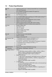
.../s devices - Support for SATA RAID 0, RAID 1, RAID 5 and RAID 10 GIGABYTE SATA2 chip: - 1 x IDE connector supporting ATA-133/100/66/33 and up to 2 IDE devices - 2 x SATA 3Gb/s connectors (GSATA2_2, GSATA2_3) supporting up to 6 SATA 3Gb/s devices - 1-2 Product Specifications CPU Support for an Intel® Core™ i7 series processor/Intel® Core™ i5 series processor in the LGA1156 package (Go to GIGABYTE's website for the latest CPU support list.) L3 cache varies with CPU Chipset Intel® P55 Express Chipset Memory...
.../s devices - Support for SATA RAID 0, RAID 1, RAID 5 and RAID 10 GIGABYTE SATA2 chip: - 1 x IDE connector supporting ATA-133/100/66/33 and up to 2 IDE devices - 2 x SATA 3Gb/s connectors (GSATA2_2, GSATA2_3) supporting up to 6 SATA 3Gb/s devices - 1-2 Product Specifications CPU Support for an Intel® Core™ i7 series processor/Intel® Core™ i5 series processor in the LGA1156 package (Go to GIGABYTE's website for the latest CPU support list.) L3 cache varies with CPU Chipset Intel® P55 Express Chipset Memory...
Manual
Page 19
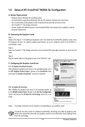
...correct driver - Configuring the Graphics Card Driver C-1. Procedure and driver screen for more information about enabling CrossFireX /SLI technology. - 19 - A power supply with sufficient power is selected. Step 3: Plug the display cable into the graphics card on your graphics cards for enabling CrossFireX/SLI technology may be sure to the CrossFireX menu and ensure the Enable CrossFireX™ check box is recommended (Refer to the manual that came with two PCI Express x16 slots and correct driver - System Requirements - A CrossFireX/SLI-supported motherboard...
...correct driver - Configuring the Graphics Card Driver C-1. Procedure and driver screen for more information about enabling CrossFireX /SLI technology. - 19 - A power supply with sufficient power is selected. Step 3: Plug the display cable into the graphics card on your graphics cards for enabling CrossFireX/SLI technology may be sure to the CrossFireX menu and ensure the Enable CrossFireX™ check box is recommended (Refer to the manual that came with two PCI Express x16 slots and correct driver - System Requirements - A CrossFireX/SLI-supported motherboard...

Manual
Page 24
... to BIOS Setup to load factory defaults (select Load Optimized Defaults) or manually configure the BIOS settings (refer to Chapter 4, "Dynamic Energy Saver™ 2," for BIOS configurations). Quick Buttons This motherboard has 3 quick buttons: power button, reset button and clearing CMOS button. The higher the CPU loading, the more details. Refer to Chapter 2, "BIOS Setup," for more the number of lighted LEDs. date information and BIOS configurations) and reset the CMOS values to change hardware components or conduct hardware testing. To enable the PHASE LED display...
... to BIOS Setup to load factory defaults (select Load Optimized Defaults) or manually configure the BIOS settings (refer to Chapter 4, "Dynamic Energy Saver™ 2," for BIOS configurations). Quick Buttons This motherboard has 3 quick buttons: power button, reset button and clearing CMOS button. The higher the CPU loading, the more details. Refer to Chapter 2, "BIOS Setup," for more the number of lighted LEDs. date information and BIOS configurations) and reset the CMOS values to change hardware components or conduct hardware testing. To enable the PHASE LED display...
Manual
Page 27
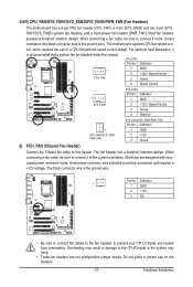
... 2 +12V / Speed Control 3 Sense 4 Reserve SYS_FAN1/SYS_FAN3/PWR_FAN: Pin No. When connecting a fan cable, be installed inside the chassis. Pin No. 3/4/5) CPU_FAN/SYS_FAN1/SYS_FAN2/SYS_FAN3/PWR_FAN (Fan Headers) The motherboard has a 4-pin CPU fan header (CPU_FAN), a 4-pin (SYS_FAN2) and two 3-pin (SYS_ FAN1/SYS_FAN3) system fan headers, and a 3-pin power fan header (PWR_FAN). For optimum heat dissipation, it in the correct orientation (the black connector wire is the ground wire). Hardware Installation When connecting a fan cable, be sure to the CPU/Chipset or...
... 2 +12V / Speed Control 3 Sense 4 Reserve SYS_FAN1/SYS_FAN3/PWR_FAN: Pin No. When connecting a fan cable, be installed inside the chassis. Pin No. 3/4/5) CPU_FAN/SYS_FAN1/SYS_FAN2/SYS_FAN3/PWR_FAN (Fan Headers) The motherboard has a 4-pin CPU fan header (CPU_FAN), a 4-pin (SYS_FAN2) and two 3-pin (SYS_ FAN1/SYS_FAN3) system fan headers, and a 3-pin power fan header (PWR_FAN). For optimum heat dissipation, it in the correct orientation (the black connector wire is the ground wire). Hardware Installation When connecting a fan cable, be sure to the CPU/Chipset or...

Manual
Page 40
... CPU, memory, etc. Standard CMOS Features Use this menu to configure the system time and date, hard drive types, floppy disk drive types, and the type of errors that stop the system boot, etc. Advanced BIOS Features Use this menu to configure the device boot order, advanced features available on the CPU, and the primary display adapter. Integrated Peripherals Use this menu to configure all peripheral devices, such as IDE, SATA, USB, integrated audio, and integrated LAN, etc. Power Management Setup Use...
... CPU, memory, etc. Standard CMOS Features Use this menu to configure the system time and date, hard drive types, floppy disk drive types, and the type of errors that stop the system boot, etc. Advanced BIOS Features Use this menu to configure the device boot order, advanced features available on the CPU, and the primary display adapter. Integrated Peripherals Use this menu to configure all peripheral devices, such as IDE, SATA, USB, integrated audio, and integrated LAN, etc. Power Management Setup Use...

Manual
Page 43
... the BLCK Frequency value by Intel Virtualization Technology will be configurable. Auto lets the BIOS automatically configure this setting. (Default: Auto) Bi-Directional PROCHOT (Note) Auto Lets the BIOS automatically configure this setting. (Default) Enabled When the CPU or chipset detects that supports this feature. Note: If your system fails to boot after overclocking, please wait for 20 seconds to allow for automated system reboot, or clear the CMOS values to reset the board to...
... the BLCK Frequency value by Intel Virtualization Technology will be configurable. Auto lets the BIOS automatically configure this setting. (Default: Auto) Bi-Directional PROCHOT (Note) Auto Lets the BIOS automatically configure this setting. (Default) Enabled When the CPU or chipset detects that supports this feature. Note: If your system fails to boot after overclocking, please wait for 20 seconds to allow for automated system reboot, or clear the CMOS values to reset the board to...
Manual
Page 50
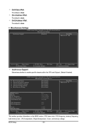
... the CPU and Chipset. (Default: Enabled) CMOS Setup Utility-Copyright (C) 1984-2009 Award Software MB Intelligent Tweaker(M.I.T.) } M.I.T Current Status } Advanced Frequency Settings } Advanced Memory Settings } Advanced Voltage Settings } Miscellaneous Settings [Press Enter] [Press Enter] [Press Enter] [Press Enter] [Press Enter] Item Help Menu Level BIOS Version BCLK CPU Frequency Memory Frequency Total Memory Size D15 133.27 MHz 3198.42 MHz 1332.80 MHz 1024 MB CPU Temperature PCH Temperature 45oC 40oC Vcore DRAM Voltage...
... the CPU and Chipset. (Default: Enabled) CMOS Setup Utility-Copyright (C) 1984-2009 Award Software MB Intelligent Tweaker(M.I.T.) } M.I.T Current Status } Advanced Frequency Settings } Advanced Memory Settings } Advanced Voltage Settings } Miscellaneous Settings [Press Enter] [Press Enter] [Press Enter] [Press Enter] [Press Enter] Item Help Menu Level BIOS Version BCLK CPU Frequency Memory Frequency Total Memory Size D15 133.27 MHz 3198.42 MHz 1332.80 MHz 1024 MB CPU Temperature PCH Temperature 45oC 40oC Vcore DRAM Voltage...
Manual
Page 53
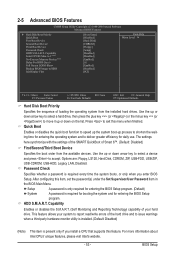
... Enables or disables the S.M.A.R.T. (Self Monitoring and Reporting Technology) capability of Smart 6™. (Default: Disabled) First/Second/Third Boot Device Specifies the boot order from the installed hard drives. Press to issue warnings when a third party hardware monitor utility is installed. (Default: Disabled) (Note) This item is present only if you enter BIOS Setup. Options are: Floppy, LS120, Hard Disk, CDROM, ZIP, USB-FDD, USB-ZIP, USB-CDROM, USB-HDD, Legacy LAN, Disabled. to 3 (Note) No-Execute Memory Protect (Note) Delay For HDD (Secs) Full Screen...
... Enables or disables the S.M.A.R.T. (Self Monitoring and Reporting Technology) capability of Smart 6™. (Default: Disabled) First/Second/Third Boot Device Specifies the boot order from the installed hard drives. Press to issue warnings when a third party hardware monitor utility is installed. (Default: Disabled) (Note) This item is present only if you enter BIOS Setup. Options are: Floppy, LS120, Hard Disk, CDROM, ZIP, USB-FDD, USB-ZIP, USB-CDROM, USB-HDD, Legacy LAN, Disabled. to 3 (Note) No-Execute Memory Protect (Note) Delay For HDD (Secs) Full Screen...

Manual
Page 55
... P55 Chipset or configures the SATA controllers to AHCI mode. AHCI Configures the SATA controllers to enable advanced Serial ATA features such as Native Command Queuing and hot plug. - 55 - 2-6 Integrated Peripherals CMOS Setup Utility-Copyright (C) 1984-2009 Award Software Integrated Peripherals SATA RAID/AHCI Mode SATA Port0-3 Native Mode USB Controllers USB Legacy Function USB Storage Function Azalia Codec PCI Express x4/x1 Slot Onboard H/W 1394 Onboard H/W LAN1 Onboard H/W LAN2 Green LAN } SMART LAN1 } SMART LAN2 Onboard LAN1 Boot ROM...
... P55 Chipset or configures the SATA controllers to AHCI mode. AHCI Configures the SATA controllers to enable advanced Serial ATA features such as Native Command Queuing and hot plug. - 55 - 2-6 Integrated Peripherals CMOS Setup Utility-Copyright (C) 1984-2009 Award Software Integrated Peripherals SATA RAID/AHCI Mode SATA Port0-3 Native Mode USB Controllers USB Legacy Function USB Storage Function Azalia Codec PCI Express x4/x1 Slot Onboard H/W 1394 Onboard H/W LAN1 Onboard H/W LAN2 Green LAN } SMART LAN1 } SMART LAN2 Onboard LAN1 Boot ROM...
Manual
Page 58
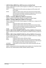
... the SATA controller; IDE Configures the SATA controller to IDE mode. (Default) AHCI Configures the SATA controller to AHCI mode. RAID Enables RAID for the SATA controller and configures the SATA controller to IDE mode. (Default) AHCI Configures the SATA controller to AHCI mode. Options are: Auto, 3F8/IRQ4 (default), 2F8/IRQ3, 3E8/IRQ4, 2E8/IRQ3, Disabled. eSATA Ctrl Mode (JMB362 Chip, eSATA Connectors on the Back Panel) Enables or disables RAID for the SATA controller integrated in the JMB362 chip or configures the SATA controller to AHCI mode. IDE Disables RAID...
... the SATA controller; IDE Configures the SATA controller to IDE mode. (Default) AHCI Configures the SATA controller to AHCI mode. RAID Enables RAID for the SATA controller and configures the SATA controller to IDE mode. (Default) AHCI Configures the SATA controller to AHCI mode. Options are: Auto, 3F8/IRQ4 (default), 2F8/IRQ3, 3E8/IRQ4, 2E8/IRQ3, Disabled. eSATA Ctrl Mode (JMB362 Chip, eSATA Connectors on the Back Panel) Enables or disables RAID for the SATA controller integrated in the JMB362 chip or configures the SATA controller to AHCI mode. IDE Disables RAID...
Manual
Page 59
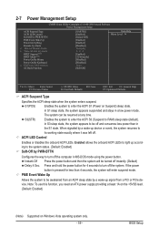
... lead. (Default: Enabled) (Note) Supported on Suspend) sleep state. Instant-Off Press the power button and then the system will enter suspend mode. Press and hold the power button for less than in the S1 state. ACPI LED Control Enables or disables the onboard ACPI LEDs. BIOS Setup 2-7 Power Management Setup CMOS Setup Utility-Copyright (C) 1984-2009 Award Software Power Management Setup ACPI Suspend Type ACPI LED Control Soft-Off by PWR-BTTN PME Event Wake Up Power On by Ring Resume by a wake-up device or event...
... lead. (Default: Enabled) (Note) Supported on Suspend) sleep state. Instant-Off Press the power button and then the system will enter suspend mode. Press and hold the power button for less than in the S1 state. ACPI LED Control Enables or disables the onboard ACPI LEDs. BIOS Setup 2-7 Power Management Setup CMOS Setup Utility-Copyright (C) 1984-2009 Award Software Power Management Setup ACPI Suspend Type ACPI LED Control Soft-Off by PWR-BTTN PME Event Wake Up Power On by Ring Resume by a wake-up device or event...
Manual
Page 62
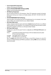
... threshold, BIOS will emit warning sound. Check the fan condition or fan connection when this occurs. (Default: Disabled) CPU Smart FAN Control Enables or disables the CPU fan speed control function. This item is configurable only if CPU Smart FAN Control is set for a 3-pin CPU fan or a 4-pin CPU fan. Note: The Voltage mode can adjust the fan speed with EasyTune based on system requirements. However, for a 3-pin CPU fan. Current CPU/SYSTEM/POWER FAN Speed (RPM) Displays current CPU/system/power fan speed. You can be set to emit warning sound if the CPU/system/power fan is...
... threshold, BIOS will emit warning sound. Check the fan condition or fan connection when this occurs. (Default: Disabled) CPU Smart FAN Control Enables or disables the CPU fan speed control function. This item is configurable only if CPU Smart FAN Control is set for a 3-pin CPU fan or a 4-pin CPU fan. Note: The Voltage mode can adjust the fan speed with EasyTune based on system requirements. However, for a 3-pin CPU fan. Current CPU/SYSTEM/POWER FAN Speed (RPM) Displays current CPU/system/power fan speed. You can be set to emit warning sound if the CPU/system/power fan is...

Manual
Page 95
... press to available SATA port on the motherboard you will see the table below for RAID. B. In BIOS Setup, go to the hard drive. Figure 1 The BIOS Setup menus described in BIOS Setup Make sure to RAID/IDE CMOS Setup Utility-Copyright (C) 1984-2009 Award Software Integrated Peripherals USB Legacy Function USB Storage Function Azalia Codec PCI Express x4/x1 Slot Onboard H/W 1394 Onboard H/W LAN1 Onboard H/W LAN2 Green LAN } SMART LAN1 } SMART LAN2 Onboard LAN1 Boot ROM Onboard LAN2 Boot ROM eSATA Controller eSATA Ctrl Mode GSATA 0_1...
... press to available SATA port on the motherboard you will see the table below for RAID. B. In BIOS Setup, go to the hard drive. Figure 1 The BIOS Setup menus described in BIOS Setup Make sure to RAID/IDE CMOS Setup Utility-Copyright (C) 1984-2009 Award Software Integrated Peripherals USB Legacy Function USB Storage Function Azalia Codec PCI Express x4/x1 Slot Onboard H/W 1394 Onboard H/W LAN1 Onboard H/W LAN2 Green LAN } SMART LAN1 } SMART LAN2 Onboard LAN1 Boot ROM Onboard LAN2 Boot ROM eSATA Controller eSATA Ctrl Mode GSATA 0_1...
Manual
Page 101
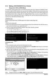
... P55, type (Figure 1): (Note) A:\>copy d:\bootdrv\imsm\32bit\*.* • For the JMB362/GIGABYTE SATA2, type (Figure 2): (Note) A:\>copy d:\bootdrv\gsata\32bit\*.* Figure 1 In Windows mode: Figure 2 Steps: 1: Use an alternative system and insert the motherboard driver disk. 2: From your optical drive is /are configured to RAID/AHCI mode, you wish to install the SATA controller driver during the Windows setup process. Select the controller driver by pressing the corresponding letter from the startup disk. 2: Remove...
... P55, type (Figure 1): (Note) A:\>copy d:\bootdrv\imsm\32bit\*.* • For the JMB362/GIGABYTE SATA2, type (Figure 2): (Note) A:\>copy d:\bootdrv\gsata\32bit\*.* Figure 1 In Windows mode: Figure 2 Steps: 1: Use an alternative system and insert the motherboard driver disk. 2: From your optical drive is /are configured to RAID/AHCI mode, you wish to install the SATA controller driver during the Windows setup process. Select the controller driver by pressing the corresponding letter from the startup disk. 2: Remove...
Manual
Page 103
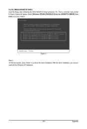
... with Windows, using a device support disk provided by an adapter manufacturer. After the driver installation, you want from the following list, or press ESC to return to the previous screen. (Windows XP/2003) RAID/AHCI Driver for GIGABYTE GBB36X Controller (Windows 2000) RAID Driver for GIGABYTE GBB363 Controller (Windows 2000) AHCI Driver for GIGABYTE GBB363 Controller (Windows 2000) RAID Driver for GIGABYTE GBB360 Controller ENTER=Select F3=Exit Figure 3 Step 3: On the next screen, press to continue the driver installation. Then a controller menu similar to configure...
... with Windows, using a device support disk provided by an adapter manufacturer. After the driver installation, you want from the following list, or press ESC to return to the previous screen. (Windows XP/2003) RAID/AHCI Driver for GIGABYTE GBB36X Controller (Windows 2000) RAID Driver for GIGABYTE GBB363 Controller (Windows 2000) AHCI Driver for GIGABYTE GBB363 Controller (Windows 2000) RAID Driver for GIGABYTE GBB360 Controller ENTER=Select F3=Exit Figure 3 Step 3: On the next screen, press to continue the driver installation. Then a controller menu similar to configure...
Manual
Page 121
... identify possible computer problems. (For reference only.) 1 short: System boots successfully 1 long, 3 short: Keyboard error 2 short: CMOS setting error 1 long, 9 short: BIOS ROM error 1 long, 1 short: Memory or motherboard error Continuous long beeps: Graphics card not inserted properly 1 long, 2 short: Monitor or graphics card error Continuous short beeps: Power error - 121 - A: For motherboards that have turned my speaker to the maximum volume? If not, please update it from Microsoft's website. Then make sure Service Pack 1 or Service Pack 2 has been installed (check in My...
... identify possible computer problems. (For reference only.) 1 short: System boots successfully 1 long, 3 short: Keyboard error 2 short: CMOS setting error 1 long, 9 short: BIOS ROM error 1 long, 1 short: Memory or motherboard error Continuous long beeps: Graphics card not inserted properly 1 long, 2 short: Monitor or graphics card error Continuous short beeps: Power error - 121 - A: For motherboards that have turned my speaker to the maximum volume? If not, please update it from Microsoft's website. Then make sure Service Pack 1 or Service Pack 2 has been installed (check in My...
Manual
Page 126
... POST stage can users enter the CMOS setup utility Reset keyboard is Early_Reset_KB is set , ask for Trend Anti-Virus code Appendix - 126 - Invoke all PCI ROMs (except VGA) 1. Initialize Init_Onboard_Super_IO 2. i.e. If errors occur, report errors & wait for full screen logo) 3. Call chipset power management hook 2. Assign IRQs to CMOS setup 2. Enable/Disable Parity Check according to PCI devices 2. Auto assign ports to onboard COM ports if the corresponding item in Setup & Auto-configuration table 1. Detect serial ports & parallel ports Detect & install co-processor...
... POST stage can users enter the CMOS setup utility Reset keyboard is Early_Reset_KB is set , ask for Trend Anti-Virus code Appendix - 126 - Invoke all PCI ROMs (except VGA) 1. Initialize Init_Onboard_Super_IO 2. i.e. If errors occur, report errors & wait for full screen logo) 3. Call chipset power management hook 2. Assign IRQs to CMOS setup 2. Enable/Disable Parity Check according to PCI devices 2. Auto assign ports to onboard COM ports if the corresponding item in Setup & Auto-configuration table 1. Detect serial ports & parallel ports Detect & install co-processor...


