
Manual
Page 1
... refer to individually install the X.H.D utility later. For a RAID 0 array that already exists, users also can use X.H.D to set up all motherboard drivers, including the X.H.D utility. The following procedure details the steps to easily add a hard drive into a RAID 0 array that before you ...7/Vista/XP. Or you run the X.H.D utility, back up a RAID 0 array later using the Auto function. eXtreme Hard Drive (X.H.D) With GIGABYTE eXtreme Hard Drive (X.H.D)(Note 1), users can quickly configure a RAIDready system for RAID 0. To automatically set up a RAID array: (Note 3): Click...
... refer to individually install the X.H.D utility later. For a RAID 0 array that already exists, users also can use X.H.D to set up all motherboard drivers, including the X.H.D utility. The following procedure details the steps to easily add a hard drive into a RAID 0 array that before you ...7/Vista/XP. Or you run the X.H.D utility, back up a RAID 0 array later using the Auto function. eXtreme Hard Drive (X.H.D) With GIGABYTE eXtreme Hard Drive (X.H.D)(Note 1), users can quickly configure a RAIDready system for RAID 0. To automatically set up a RAID array: (Note 3): Click...
Manual
Page 1
GA-P55-UD6 LGA1156 socket motherboard for Intel® Core™ i7 processor family/ Intel® Core™ i5 processor family User's Manual Rev. 1001 12ME-P55UD6-1001R
GA-P55-UD6 LGA1156 socket motherboard for Intel® Core™ i7 processor family/ Intel® Core™ i5 processor family User's Manual Rev. 1001 12ME-P55UD6-1001R
Manual
Page 3
... the product, read the Quick Installation Guide included with the product. Check your motherboard looks like this product, GIGABYTE provides the following types of documentations: For quick set-up of GIGABYTE. For product-related information, check on our website at: http://www.gigabyte.com.tw Identifying Your Motherboard Revision The revision number on our website.
... the product, read the Quick Installation Guide included with the product. Check your motherboard looks like this product, GIGABYTE provides the following types of documentations: For quick set-up of GIGABYTE. For product-related information, check on our website at: http://www.gigabyte.com.tw Identifying Your Motherboard Revision The revision number on our website.
Manual
Page 4
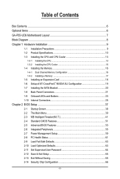
Table of Contents Box Contents...6 Optional Items...6 GA-P55-UD6 Motherboard Layout 7 Block Diagram...8 Chapter 1 Hardware Installation 9 1-1 Installation Precautions 9 1-2 Product Specifications 10 1-3 Installing the CPU and CPU Cooler 13 1-3-1 Installing the CPU 13 1-3-2 Installing the CPU ...
Table of Contents Box Contents...6 Optional Items...6 GA-P55-UD6 Motherboard Layout 7 Block Diagram...8 Chapter 1 Hardware Installation 9 1-1 Installation Precautions 9 1-2 Product Specifications 10 1-3 Installing the CPU and CPU Cooler 13 1-3-1 Installing the CPU 13 1-3-2 Installing the CPU ...
Manual
Page 6
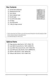
... SATA power cable (Part No. 12CF1-2SERPW-0*R) S/PDIF In cable (Part No. 12CR1-1SPDIN-0*R) COM port cable (Part No. 12CF1-1CM001-3*R) - 6 - Box Contents GA-P55-UD6 motherboard Motherboard driver disk User's Manual Quick Installation Guide One IDE cable Four SATA 3Gb/s cables I/O Shield One SATA bracket 2-Way SLI bridge connector • The box... contents above are subject to change without notice. • The motherboard image is for reference only and the actual items shall depend on the product package you obtain.
... SATA power cable (Part No. 12CF1-2SERPW-0*R) S/PDIF In cable (Part No. 12CR1-1SPDIN-0*R) COM port cable (Part No. 12CF1-1CM001-3*R) - 6 - Box Contents GA-P55-UD6 motherboard Motherboard driver disk User's Manual Quick Installation Guide One IDE cable Four SATA 3Gb/s cables I/O Shield One SATA bracket 2-Way SLI bridge connector • The box... contents above are subject to change without notice. • The motherboard image is for reference only and the actual items shall depend on the product package you obtain.
Manual
Page 7
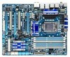
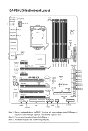
... due to a hardware limitation, the PCIEX1_1 slot can only accommodate a shorter PCI Express x1 expansion card. GA-P55-UD6 Motherboard Layout KB_USB R_SPDIF SYS_FAN3 ATX_12V_2X USB_1394_ESATA_2 LGA1156 CPU_FAN PW_SW USB_1394_ESATA_1 USB_LAN2 USB_LAN1 JMB362 F_AUDIO AUDIO PCIEX1_1 (Note 1) RTL8111D PCH_FAN RTL8111D...Intel® P55 PCIEX16_1 CODEC CD_IN SPDIF_I PCI1 PCIEX8_1 GA-P55-UD6 BATTERY TPM IC (Note 3) B_BIOS M_BIOS SPDIF_O PCI2 ACPI LED TSB43AB23 DDR3_3 DDR3_2 DDR3_1 DDR3_6 DDR3_5 DDR3_4 MD1 MD2 ATX GD1 GD2 PWR_FAN PHASE LED SYS_FAN1 JMB362 GIGABYTE SATA2 RST_SW...
... due to a hardware limitation, the PCIEX1_1 slot can only accommodate a shorter PCI Express x1 expansion card. GA-P55-UD6 Motherboard Layout KB_USB R_SPDIF SYS_FAN3 ATX_12V_2X USB_1394_ESATA_2 LGA1156 CPU_FAN PW_SW USB_1394_ESATA_1 USB_LAN2 USB_LAN1 JMB362 F_AUDIO AUDIO PCIEX1_1 (Note 1) RTL8111D PCH_FAN RTL8111D...Intel® P55 PCIEX16_1 CODEC CD_IN SPDIF_I PCI1 PCIEX8_1 GA-P55-UD6 BATTERY TPM IC (Note 3) B_BIOS M_BIOS SPDIF_O PCI2 ACPI LED TSB43AB23 DDR3_3 DDR3_2 DDR3_1 DDR3_6 DDR3_5 DDR3_4 MD1 MD2 ATX GD1 GD2 PWR_FAN PHASE LED SYS_FAN1 JMB362 GIGABYTE SATA2 RST_SW...
Manual
Page 9
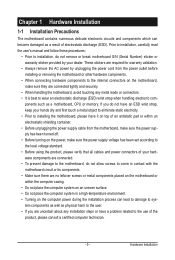
...wear an electrostatic discharge (ESD) wrist strap when handling electronic com- Hardware Installation Chapter 1 Hardware Installation 1-1 Installation Precautions The motherboard contains numerous delicate electronic circuits and components which can lead to damage to system components as well as physical harm to the ...wrist strap, keep your hands dry and first touch a metal object to eliminate static electricity. • Prior to installing the motherboard, please have a problem related to the use of electrostatic discharge (ESD). Prior to installation, carefully read the user's manual ...
...wear an electrostatic discharge (ESD) wrist strap when handling electronic com- Hardware Installation Chapter 1 Hardware Installation 1-1 Installation Precautions The motherboard contains numerous delicate electronic circuits and components which can lead to damage to system components as well as physical harm to the ...wrist strap, keep your hands dry and first touch a metal object to eliminate static electricity. • Prior to installing the motherboard, please have a problem related to the use of electrostatic discharge (ESD). Prior to installation, carefully read the user's manual ...

Manual
Page 12
.... (Note 2) For optimum performance, if only one PCI Express graphics card is to be installed, be sure to install it in EasyTune may differ by motherboard model. (Note 7) This feature is optional due to different regional policy.
.... (Note 2) For optimum performance, if only one PCI Express graphics card is to be installed, be sure to install it in EasyTune may differ by motherboard model. (Note 7) This feature is optional due to different regional policy.

Manual
Page 13
... support list.) • Always turn on the CPU. Locate the alignment keys on the motherboard CPU socket and the notches on the computer if the CPU cooler is not recommended that the motherboard supports the CPU. (Go to GIGABYTE's website for the peripherals. Hardware Installation age of the CPU Socket LGA1156 CPU Notch...
... support list.) • Always turn on the CPU. Locate the alignment keys on the motherboard CPU socket and the notches on the computer if the CPU cooler is not recommended that the motherboard supports the CPU. (Go to GIGABYTE's website for the peripherals. Hardware Installation age of the CPU Socket LGA1156 CPU Notch...

Manual
Page 14
.... Step 1: Gently press the CPU socket lever handle down and away from the power outlet to prevent damage to correctly install the CPU into the motherboard CPU socket. Follow the steps below to the CPU. Then completely lift the CPU socket lever and the metal load plate will be lifted as...
.... Step 1: Gently press the CPU socket lever handle down and away from the power outlet to prevent damage to correctly install the CPU into the motherboard CPU socket. Follow the steps below to the CPU. Then completely lift the CPU socket lever and the metal load plate will be lifted as...

Manual
Page 15
1-3-2 Installing the CPU Cooler Follow the steps below to correctly install the CPU cooler on the motherboard. (The following procedure uses Intel® boxed cooler as the picture above shows, the installation is complete. Direction of the Arrow Sign on ...the surface of the installed CPU. Push down each push pin. Step 6: Finally, attach the power connector of the motherboard. Step 4: You should hear a "click" when pushing down on the motherboard. Inadequately removing the CPU cooler may adhere to the CPU fan header (CPU_FAN) on the push pins diagonally. Use extreme...
1-3-2 Installing the CPU Cooler Follow the steps below to correctly install the CPU cooler on the motherboard. (The following procedure uses Intel® boxed cooler as the picture above shows, the installation is complete. Direction of the Arrow Sign on ...the surface of the installed CPU. Push down each push pin. Step 6: Finally, attach the power connector of the motherboard. Step 4: You should hear a "click" when pushing down on the motherboard. Inadequately removing the CPU cooler may adhere to the CPU fan header (CPU_FAN) on the push pins diagonally. Use extreme...
Manual
Page 16
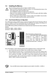
...of the same capacity, brand, speed, and chips be sure to insert the memory, switch the direction. 1-4-1 Dual Channel Memory Configuration This motherboard provides six DDR3 memory sockets and supports Dual Channel Technology. When enabling Dual Channel mode with two memory modules, be used. (Go to ... DS/SS SS SS (SS=Single-Sided, DS=Double-Sided, "- -"=No Memory) DS/SS DDR3_3 DDR3_2 DDR3_1 DDR3_6 DDR3_5 DDR3_4 Due to GIGABYTE's website for optimum performance. If only one DDR3 memory module is installed. 2. If you begin to be enabled if only one direction. Enabling...
...of the same capacity, brand, speed, and chips be sure to insert the memory, switch the direction. 1-4-1 Dual Channel Memory Configuration This motherboard provides six DDR3 memory sockets and supports Dual Channel Technology. When enabling Dual Channel mode with two memory modules, be used. (Go to ... DS/SS SS SS (SS=Single-Sided, DS=Double-Sided, "- -"=No Memory) DS/SS DDR3_3 DDR3_2 DDR3_1 DDR3_6 DDR3_5 DDR3_4 Due to GIGABYTE's website for optimum performance. If only one DDR3 memory module is installed. 2. If you begin to be enabled if only one direction. Enabling...

Manual
Page 17
..., make sure to turn off the computer and unplug the power cord from the power outlet to prevent damage to install DDR3 DIMMs on this motherboard. Notch DDR3 DIMM A DDR3 memory module has a notch, so it vertically into place when the memory module is securely inserted. - 17 - Hardware Installation Place the...
..., make sure to turn off the computer and unplug the power cord from the power outlet to prevent damage to install DDR3 DIMMs on this motherboard. Notch DDR3 DIMM A DDR3 memory module has a notch, so it vertically into place when the memory module is securely inserted. - 17 - Hardware Installation Place the...
Manual
Page 18
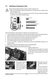
... Express x16 Slot (PCIEX16_1) PCI Express x16 Slot (PCIEX8_1/PCIEX4_1) PCI Slot Follow the steps below to install an expansion card: • Make sure the motherboard supports the expansion card. 1-5 Installing an Expansion Card Read the following guidelines before installing an expansion card to make any required BIOS changes for your...
... Express x16 Slot (PCIEX16_1) PCI Express x16 Slot (PCIEX8_1/PCIEX4_1) PCI Slot Follow the steps below to install an expansion card: • Make sure the motherboard supports the expansion card. 1-5 Installing an Expansion Card Read the following guidelines before installing an expansion card to make any required BIOS changes for your...
Manual
Page 19
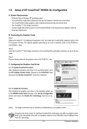
... bridge connectors may differ by graphics cards. Browse to the manual that came with two PCI Express x16 slots and correct driver - C-2. A CrossFireX/SLI-supported motherboard with your graphics cards. 1-6 Setup of identical brand and chip and correct driver - Refer to the Set SLI Configuration screen and ensure the Enable SLI...
... bridge connectors may differ by graphics cards. Browse to the manual that came with two PCI Express x16 slots and correct driver - C-2. A CrossFireX/SLI-supported motherboard with your graphics cards. 1-6 Setup of identical brand and chip and correct driver - Refer to the Set SLI Configuration screen and ensure the Enable SLI...

Manual
Page 20
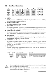
... of the SATA signal cable and SATA power cable to your SATA device. Before connecting the SATA signal cable, make sure to turn off your motherboard. Step 2: Connect the SATA cable from the bracket to the power supply. SATA Bracket SATA Signal Cable SATA Power Cable External SATA Connector Power Connector...
... of the SATA signal cable and SATA power cable to your SATA device. Before connecting the SATA signal cable, make sure to turn off your motherboard. Step 2: Connect the SATA cable from the bracket to the power supply. SATA Bracket SATA Signal Cable SATA Power Cable External SATA Connector Power Connector...
Manual
Page 21
... cable connected to prevent an electrical short inside the cable connector. - 21 - Use this feature, ensure that your device and then remove it from the motherboard. • When removing the cable, pull it side to side to a back panel connector, first remove the cable from the connector. Use the port to...
... cable connected to prevent an electrical short inside the cable connector. - 21 - Use this feature, ensure that your device and then remove it from the motherboard. • When removing the cable, pull it side to side to a back panel connector, first remove the cable from the connector. Use the port to...

Manual
Page 23
... (green LED) GD2: Excessive overvoltage or overloading (yellow LED) Memory: MD1: Normal working conditions; 1-9 Onboard LEDs and Buttons CPU VTT/Memory Phase Indicator LEDs This motherboard contains 4 phase indicator LEDs controlled by the system BIOS to improper plug/unplug actions. the yellow LEDs will be illuminated when an excessive overvoltage or...
... (green LED) GD2: Excessive overvoltage or overloading (yellow LED) Memory: MD1: Normal working conditions; 1-9 Onboard LEDs and Buttons CPU VTT/Memory Phase Indicator LEDs This motherboard contains 4 phase indicator LEDs controlled by the system BIOS to improper plug/unplug actions. the yellow LEDs will be illuminated when an excessive overvoltage or...

Manual
Page 24
...). The higher the CPU loading, the more details. To enable the PHASE LED display function, please first enable Dynamic Energy Saver™ 2. Quick Buttons This motherboard has 3 quick buttons: power button, reset button and clearing CMOS button.
...). The higher the CPU loading, the more details. To enable the PHASE LED display function, please first enable Dynamic Energy Saver™ 2. Quick Buttons This motherboard has 3 quick buttons: power button, reset button and clearing CMOS button.

Manual
Page 25
... devices and your devices are compliant with the connectors you wish to connect. • Before installing the devices, be sure to the connector on the motherboard. - 25 -
... devices and your devices are compliant with the connectors you wish to connect. • Before installing the devices, be sure to the connector on the motherboard. - 25 -


