User Manual
Page 1
...the property of GBT. GA-K8NSNXP AMD Socket 754 Processor Motherboard User's Manual Rev. 1002 12ME-K8NSNXP-1002 Copyright © 2005 GIGABYTE TECHNOLOGY CO., LTD Copyright by GIGA-BYTE TECHNOLOGY CO., LTD. ("GBT"). Due to update the information contained herein. Notice Please do not remove any labels on motherboard, this may be out... be reproduced or transmitted in any errors or omissions that may appear in this manual may void the warranty of this motherboard. The author assumes no responsibility for any from without the expressed, written permission of their respective owners.
...the property of GBT. GA-K8NSNXP AMD Socket 754 Processor Motherboard User's Manual Rev. 1002 12ME-K8NSNXP-1002 Copyright © 2005 GIGABYTE TECHNOLOGY CO., LTD Copyright by GIGA-BYTE TECHNOLOGY CO., LTD. ("GBT"). Due to update the information contained herein. Notice Please do not remove any labels on motherboard, this may be out... be reproduced or transmitted in any errors or omissions that may appear in this manual may void the warranty of this motherboard. The author assumes no responsibility for any from without the expressed, written permission of their respective owners.

User Manual
Page 3
Motherboard GA-K8NSNXP Apr. 2, 2004
Motherboard GA-K8NSNXP Apr. 2, 2004
User Manual
Page 4
You might experience system unable to boot up normally. English Read Me First! AGP 4X/8X notch Caution: AGP 2X card is AGP 4X/8X. When you installing AGP card, please make sure your AGP card has "AGP 4X/8X (1.5V) notch" (show below), please make sure the following notice is fully understood and practiced. Please insert an AGP 4X/8X card. If your AGP card is not supported by nVIDIA® nForceTM 3 250. GA-K8NSNXP Motherboard - 4 -
You might experience system unable to boot up normally. English Read Me First! AGP 4X/8X notch Caution: AGP 2X card is AGP 4X/8X. When you installing AGP card, please make sure your AGP card has "AGP 4X/8X (1.5V) notch" (show below), please make sure the following notice is fully understood and practiced. Please insert an AGP 4X/8X card. If your AGP card is not supported by nVIDIA® nForceTM 3 250. GA-K8NSNXP Motherboard - 4 -
User Manual
Page 5
...near by the edges and try not touch the IC chips, leads or connectors, or other components. 4. Sometimes you can still attach the motherboard to the chassis... Unplug your computer. 1. Place components on a grounded antistatic pad or on the bag that the ATX power supply is ...may be careful of the spacers (the spacer may need to use the plastic springs to isolate the screw from the system. 5. Computer motherboards and expansion cards contain very delicate Integrated Circuit (IC) chips. To protect them against damage from static electricity, you should follow some precautions...
...near by the edges and try not touch the IC chips, leads or connectors, or other components. 4. Sometimes you can still attach the motherboard to the chassis... Unplug your computer. 1. Place components on a grounded antistatic pad or on the bag that the ATX power supply is ...may be careful of the spacers (the spacer may need to use the plastic springs to isolate the screw from the system. 5. Computer motherboards and expansion cards contain very delicate Integrated Circuit (IC) chips. To protect them against damage from static electricity, you should follow some precautions...
User Manual
Page 6
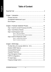
English Table of Content Read Me First 4 Chapter 1 Introduction 8 Features Summary 8 GA-K8NSNXP Motherboard Layout 10 Block Diagram 11 Chapter 2 Hardware Installation Process 13 Step 1: Install the Central Processing Unit (CPU 14 Step 2: Install Memory Modules 16 Step 3: Install ... Features 40 Advanced BIOS Features 42 Integrated Peripherals 44 Power Management Setup 48 PnP/PCI Configurations 50 PC Health Status 51 Frequency/Voltage Control 52 GA-K8NSNXP Motherboard - 6 -
English Table of Content Read Me First 4 Chapter 1 Introduction 8 Features Summary 8 GA-K8NSNXP Motherboard Layout 10 Block Diagram 11 Chapter 2 Hardware Installation Process 13 Step 1: Install the Central Processing Unit (CPU 14 Step 2: Install Memory Modules 16 Step 3: Install ... Features 40 Advanced BIOS Features 42 Integrated Peripherals 44 Power Management Setup 48 PnP/PCI Configurations 50 PC Health Status 51 Frequency/Voltage Control 52 GA-K8NSNXP Motherboard - 6 -
User Manual
Page 8
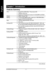
GA-K8NSNXP Motherboard - 8 - English Chapter 1 Introduction Features Summary CPU Chipset Memory Slots On-Board IDE On-Board Floppy On-Board SATA On-Board Peripherals On-Board LAN On-...
GA-K8NSNXP Motherboard - 8 - English Chapter 1 Introduction Features Summary CPU Chipset Memory Slots On-Board IDE On-Board Floppy On-Board SATA On-Board Peripherals On-Board LAN On-...
User Manual
Page 10
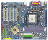
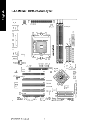
English GA-K8NSNXP Motherboard Layout DDR1 DDR2 DDR3 USB LAN2 (10/100) KB_MS ATX_12V VRM_CONN CPU_FAN RAM_LED ATX COMA LPT IDE2 PWR_FAN COMB USB LAN1 (Gigabit Ethernet) IDE1 GA-K8NSNXP ICS1883 AUDIO F_AUDIO CD_IN 2X_DET CODEC IT8712 AGP SUR_CEN SPDIF_IO SOCKET 754 SATA0_SB SATA1_SB PCI1 nVIDIA® nForce™ 3 250 PCI2 FDD BAT CLR_CMOS BACKUP... Marvell 8001 SYS_FAN GAME IR_CIR INFO_LINK PCI3 TSB82AA2 PCI4 TSB81BA3 SiI3512 GigaRAID IT8212 PCI5 IDE4 IDE3 CI F2_1394 PWR_LED F1_1394 SATA1_SII SATA0_SII F_PANEL F_USB1 GA-K8NSNXP Motherboard - 10 -
English GA-K8NSNXP Motherboard Layout DDR1 DDR2 DDR3 USB LAN2 (10/100) KB_MS ATX_12V VRM_CONN CPU_FAN RAM_LED ATX COMA LPT IDE2 PWR_FAN COMB USB LAN1 (Gigabit Ethernet) IDE1 GA-K8NSNXP ICS1883 AUDIO F_AUDIO CD_IN 2X_DET CODEC IT8712 AGP SUR_CEN SPDIF_IO SOCKET 754 SATA0_SB SATA1_SB PCI1 nVIDIA® nForce™ 3 250 PCI2 FDD BAT CLR_CMOS BACKUP... Marvell 8001 SYS_FAN GAME IR_CIR INFO_LINK PCI3 TSB82AA2 PCI4 TSB81BA3 SiI3512 GigaRAID IT8212 PCI5 IDE4 IDE3 CI F2_1394 PWR_LED F1_1394 SATA1_SII SATA0_SII F_PANEL F_USB1 GA-K8NSNXP Motherboard - 10 -

User Manual
Page 14
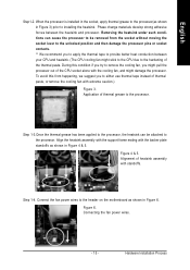
...pins to the 90-degree directly. Do not force the processor into place. Pull the lever to see that matches up to the following warning: 1. GA-K8NSNXP Motherboard - 14 - If you to the socket and gently lower it will result. 6. The pin 1 location is performed in four main steps: Step1-1....) Before installing the processor and cooling fan, adhere to a triangle on the socket as shown in Figure 1.(90o to the plane of the motherboard) prior to the locked position while holding pressure on the center of the processor. Apply thermal grease between the processor and cooling fan. 5. ...
...pins to the 90-degree directly. Do not force the processor into place. Pull the lever to see that matches up to the following warning: 1. GA-K8NSNXP Motherboard - 14 - If you to the socket and gently lower it will result. 6. The pin 1 location is performed in four main steps: Step1-1....) Before installing the processor and cooling fan, adhere to a triangle on the socket as shown in Figure 1.(90o to the plane of the motherboard) prior to the locked position while holding pressure on the center of the processor. Apply thermal grease between the processor and cooling fan. 5. ...
User Manual
Page 15
... Step1-2. When the processor is installed in the socket, apply thermal grease to the processor(as shown in Figure 3) prior to the header on the motherboard as shown in Figure 6. Figure 4 & 5. Connect the fan power wires to installing the heatsink.
... Step1-2. When the processor is installed in the socket, apply thermal grease to the processor(as shown in Figure 3) prior to the header on the motherboard as shown in Figure 6. Figure 4 & 5. Connect the fan power wires to installing the heatsink.
User Manual
Page 16
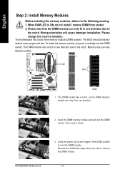
... automatically detects memory type and size. The BIOS will cause improper installation. To install the memory module, just push it down. The motherboard has 3 dual inline memory module (DIMM) sockets. GA-K8NSNXP Motherboard 3. Please change the insert orientation. English Step 2: Install Memory Modules Before installing the memory modules, adhere to the notch. Please note...
... automatically detects memory type and size. The BIOS will cause improper installation. To install the memory module, just push it down. The motherboard has 3 dual inline memory module (DIMM) sockets. GA-K8NSNXP Motherboard 3. Please change the insert orientation. English Step 2: Install Memory Modules Before installing the memory modules, adhere to the notch. Please note...

User Manual
Page 17
... expansion card from the operating system. Install related driver from BIOS. 8. Please align the AGP card to AGP 2X (3.3V) is locked by the chipset. GA-K8NSNXP Motherboard - 17 - Replace your computer's chassis cover, screws and slot bracket from the computer. 3. Remove your computer's chassis cover. 7. Power on the card are indeed seated...
... expansion card from the operating system. Install related driver from BIOS. 8. Please align the AGP card to AGP 2X (3.3V) is locked by the chipset. GA-K8NSNXP Motherboard - 17 - Replace your computer's chassis cover, screws and slot bracket from the computer. 3. Remove your computer's chassis cover. 7. Power on the card are indeed seated...
User Manual
Page 18
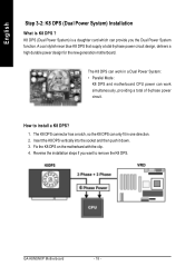
... is a daughter card which can work in one direction. 2. Insert the K8 DPS vertically into the socket and then push it down. 3. GA-K8NSNXP Motherboard - 18 - A cool stylish neon blue K8 DPS that supply a total 6-phase power circuit design, delivers a high durable power design for the new generation... motherboard. How to remove the K8 DPS. Fix the K8 DPS on the motherbard with the clip. 4. The K8 DPS can work simultaneously, providing a...
... is a daughter card which can work in one direction. 2. Insert the K8 DPS vertically into the socket and then push it down. 3. GA-K8NSNXP Motherboard - 18 - A cool stylish neon blue K8 DPS that supply a total 6-phase power circuit design, delivers a high durable power design for the new generation... motherboard. How to remove the K8 DPS. Fix the K8 DPS on the motherbard with the clip. 4. The K8 DPS can work simultaneously, providing a...
User Manual
Page 20
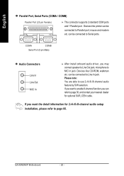
... (25 pin Female) This connector supports 2 standard COM ports and 1 Parallel port. mouse and modem etc. Please note: You are able to MIC In jack. GA-K8NSNXP Motherboard - 20 - If you want to enable 8-channel function you can be connected to page 30, and contact your nearest dealer for 2-/4-/6-/8-channel audio setup installation...
... (25 pin Female) This connector supports 2 standard COM ports and 1 Parallel port. mouse and modem etc. Please note: You are able to MIC In jack. GA-K8NSNXP Motherboard - 20 - If you want to enable 8-channel function you can be connected to page 30, and contact your nearest dealer for 2-/4-/6-/8-channel audio setup installation...
User Manual
Page 22
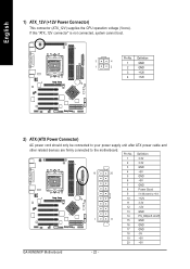
... +12V 11 3.3V 12 -12V 13 GND 14 PS_ON(soft on/off) 1 11 15 GND 16 GND 17 GND 18 -5V 19 +5V 20 +5V GA-K8NSNXP Motherboard - 22 - If this "ATX_12V connector" is not connected, system cannot boot. Pin No. Pin No. English 1) ATX_12V (+12V Power Connector) This connector (ATX_12V) supplies the...) AC power cord should only be connected to your power supply unit after ATX power cable and other related devices are firmly connected to the motherboard.
... +12V 11 3.3V 12 -12V 13 GND 14 PS_ON(soft on/off) 1 11 15 GND 16 GND 17 GND 18 -5V 19 +5V 20 +5V GA-K8NSNXP Motherboard - 22 - If this "ATX_12V connector" is not connected, system cannot boot. Pin No. Pin No. English 1) ATX_12V (+12V Power Connector) This connector (ATX_12V) supplies the...) AC power cord should only be connected to your power supply unit after ATX power cable and other related devices are firmly connected to the motherboard.
User Manual
Page 24
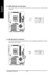
Sometimes will not work. Definition 1 Power 2 GND 1 GA-K8NSNXP Motherboard - 24 - Definition 1 GND 1 2 +12V 3 NC 6) NB_FAN (Chip Fan Connector) If you to link with the cooling fan on the system case to lower the system temperature. English 5) PWR_FAN (Power Fan Connector) This connector allows you installed wrong direction, the chip fan will damage the chip fan. (Usually black cable is GND) Pin No. Pin No.
Sometimes will not work. Definition 1 Power 2 GND 1 GA-K8NSNXP Motherboard - 24 - Definition 1 GND 1 2 +12V 3 NC 6) NB_FAN (Chip Fan Connector) If you to link with the cooling fan on the system case to lower the system temperature. English 5) PWR_FAN (Power Fan Connector) This connector allows you installed wrong direction, the chip fan will damage the chip fan. (Usually black cable is GND) Pin No. Pin No.
User Manual
Page 26
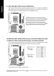
... connect the Serial ATA device to have proper operation. If you wish to use IDE3 and IDE4, please use it in unity with the Pin1. GA-K8NSNXP Motherboard - 26 - Then, install the correct driver to this connector. SATA0_SB / SATA1_SB 1 7 SATA0_SII / SATA1_SII 7 1 Pin No. 1 2 3 4 5 6 7 Definition GND TXP TXN GND RXN RXP GND These SATA...
... connect the Serial ATA device to have proper operation. If you wish to use IDE3 and IDE4, please use it in unity with the Pin1. GA-K8NSNXP Motherboard - 26 - Then, install the correct driver to this connector. SATA0_SB / SATA1_SB 1 7 SATA0_SII / SATA1_SII 7 1 Pin No. 1 2 3 4 5 6 7 Definition GND TXP TXN GND RXN RXP GND These SATA...
User Manual
Page 28
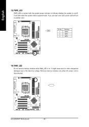
Pin No. Remove memory modules only when AC power cord is on /off. It will turn to another color. Definition 1 1 MPD+ 2 MPD- 3 MPD- 14) RAM_LED Do not remove memory modules while RAM_LED is disconnected. + _ GA-K8NSNXP Motherboard - 28 - If you use dual color LED, power LED will blink when the system enters suspend mode. It might cause short or other unexpected damages due to the stand by voltage. English 13) PWR_LED PWR_LED is connect with the system power indicator to indicate whether the system is on .
Pin No. Remove memory modules only when AC power cord is on /off. It will turn to another color. Definition 1 1 MPD+ 2 MPD- 3 MPD- 14) RAM_LED Do not remove memory modules while RAM_LED is disconnected. + _ GA-K8NSNXP Motherboard - 28 - If you use dual color LED, power LED will blink when the system enters suspend mode. It might cause short or other unexpected damages due to the stand by voltage. English 13) PWR_LED PWR_LED is connect with the system power indicator to indicate whether the system is on .
User Manual
Page 30
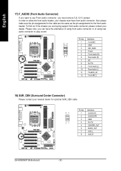
... connector, please contact your chassis must remove 5-6, 9-10 Jumper. Pin No. Definition 87 1 SUR OUTL 2 SUR OUTR 3 GND 21 4 No Pin 5 CENTER_OUT 6 BASS_OUT 7 AUX_L 8 AUX_R GA-K8NSNXP Motherboard - 30 - Also please make sure the pin assignments for the front audio header.
... connector, please contact your chassis must remove 5-6, 9-10 Jumper. Pin No. Definition 87 1 SUR OUTL 2 SUR OUTR 3 GND 21 4 No Pin 5 CENTER_OUT 6 BASS_OUT 7 AUX_L 8 AUX_R GA-K8NSNXP Motherboard - 30 - Also please make sure the pin assignments for the front audio header.
User Manual
Page 32
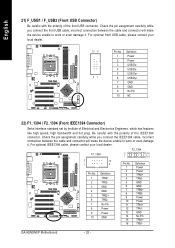
... Definition Power Power TPA0+ TPA0GND GND TPB0+ TPB0Power Power TPA1+ TPA1GND No Pin TPB1+ TPB1- Be careful with the polarity of the front USB connector. GA-K8NSNXP Motherboard - 32 - For optional front USB cable, please contact your local dealer. For optional IEEE1394 cable, please contact your local dealer. 10 9 21 Pin No. 1 2 3 4 5 6 7 8 9 10...
... Definition Power Power TPA0+ TPA0GND GND TPB0+ TPB0Power Power TPA1+ TPA1GND No Pin TPB1+ TPB1- Be careful with the polarity of the front USB connector. GA-K8NSNXP Motherboard - 32 - For optional front USB cable, please contact your local dealer. For optional IEEE1394 cable, please contact your local dealer. 10 9 21 Pin No. 1 2 3 4 5 6 7 8 9 10...

User Manual
Page 34
... connect some external devices to enable or disable the "case open" item in BIOS if the system case begin remove. 1 Pin No. Definition 1 Signal 2 GND GA-K8NSNXP Motherboard - 34 -
... connect some external devices to enable or disable the "case open" item in BIOS if the system case begin remove. 1 Pin No. Definition 1 Signal 2 GND GA-K8NSNXP Motherboard - 34 -


