User Manual
Page 6
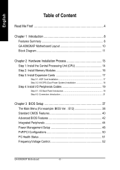
... Step 2: Install Memory Modules 16 Step 3: Install Expansion Cards 17 Step 3-1: AGP Card Installation 17 Step 3-2: K8 DPS (Dual Power System) Installation 18 Step 4: Install I/O Peripherals Cables 19 Step 4-1: I/O Back Panel Introduction 19 Step 4-2: Connectors Introduction 21 Chapter 3 BIOS Setup 37 The Main Menu (For example: BIOS Ver. : E12 38 Standard CMOS Features 40 Advanced BIOS Features 42 Integrated Peripherals 44 Power Management Setup 48 PnP/PCI Configurations 50 PC Health Status 51 Frequency/Voltage Control 52 GA-K8NSNXP Motherboard - 6 -
... Step 2: Install Memory Modules 16 Step 3: Install Expansion Cards 17 Step 3-1: AGP Card Installation 17 Step 3-2: K8 DPS (Dual Power System) Installation 18 Step 4: Install I/O Peripherals Cables 19 Step 4-1: I/O Back Panel Introduction 19 Step 4-2: Connectors Introduction 21 Chapter 3 BIOS Setup 37 The Main Menu (For example: BIOS Ver. : E12 38 Standard CMOS Features 40 Advanced BIOS Features 42 Integrated Peripherals 44 Power Management Setup 48 PnP/PCI Configurations 50 PC Health Status 51 Frequency/Voltage Control 52 GA-K8NSNXP Motherboard - 6 -
User Manual
Page 8
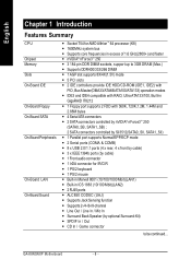
... Features Summary CPU Chipset Memory Slots On-Board IDE On-Board Floppy On-Board SATA On-Board Peripherals On-Board LAN On-Board Sound y Socket 754 for AMD Althlon™ 64 processor (K8) y 1600MHz system bus y Supports core frequencies in excess of 1.6 GHz(2800+) and faster y nVIDIA® nForce3TM 250 y 3 184-pin DDR DIMM sockets, support up to 3GB DRAM (Max.) y Supports DDR400/333/266 DIMM y 1 AGP slot supports 8X/4X(1.5V) mode y 5 PCI slots y 2 IDE controllers provide IDE HDD/CD-ROM (IDE1, IDE2) with PIO, Bus Master(DMA33...
... Features Summary CPU Chipset Memory Slots On-Board IDE On-Board Floppy On-Board SATA On-Board Peripherals On-Board LAN On-Board Sound y Socket 754 for AMD Althlon™ 64 processor (K8) y 1600MHz system bus y Supports core frequencies in excess of 1.6 GHz(2800+) and faster y nVIDIA® nForce3TM 250 y 3 184-pin DDR DIMM sockets, support up to 3GB DRAM (Max.) y Supports DDR400/333/266 DIMM y 1 AGP slot supports 8X/4X(1.5V) mode y 5 PCI slots y 2 IDE controllers provide IDE HDD/CD-ROM (IDE1, IDE2) with PIO, Bus Master(DMA33...

User Manual
Page 9
... mode for HDD y Supports IDE bus master operation y Supports ATA133/RAID mode switch by BIOS y Displays status and error checking messages during boot-up y Mirroring supports automatic background rebuilds y Features LBA and Extended Interrupt 13 drive translation in controller onboard BIOS I/O Control y IT8712 Hardware Monitor y CPU/System/Power fan revolution detect y CPU/System/Power fan fail warning y CPU temperature detect y CPU warning temperature y System voltage detect y CPU smart fan control y Thermal shutdown function BIOS y Licensed AWARD BIOS y Supports Dual BIOS...
... mode for HDD y Supports IDE bus master operation y Supports ATA133/RAID mode switch by BIOS y Displays status and error checking messages during boot-up y Mirroring supports automatic background rebuilds y Features LBA and Extended Interrupt 13 drive translation in controller onboard BIOS I/O Control y IT8712 Hardware Monitor y CPU/System/Power fan revolution detect y CPU/System/Power fan fail warning y CPU temperature detect y CPU warning temperature y System voltage detect y CPU smart fan control y Thermal shutdown function BIOS y Licensed AWARD BIOS y Supports Dual BIOS...
User Manual
Page 13
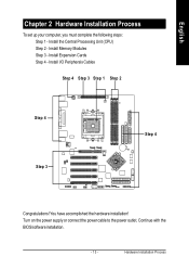
You have accomplished the hardware installation! Turn on the power supply or connect the power cable to the power outlet. English Chapter 2 Hardware Installation Process To set up your computer, you must complete the following steps: Step 1 - Install I/O Peripherals Cables Step 4 Step 3 Step 1 Step 2 Step 4 Step 3 Step 4 Congratulations! Install Expansion Cards Step 4 - Hardware Installation Process Continue with the BIOS/software installation. - 13 - Install the Central Processing Unit (CPU) Step 2 - Install Memory Modules Step 3 -
You have accomplished the hardware installation! Turn on the power supply or connect the power cable to the power outlet. English Chapter 2 Hardware Installation Process To set up your computer, you must complete the following steps: Step 1 - Install I/O Peripherals Cables Step 4 Step 3 Step 1 Step 2 Step 4 Step 3 Step 4 Congratulations! Install Expansion Cards Step 4 - Hardware Installation Process Continue with the BIOS/software installation. - 13 - Install the Central Processing Unit (CPU) Step 2 - Install Memory Modules Step 3 -
User Manual
Page 20
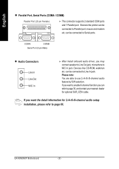
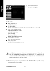
... connected to use 2-/4-/6-/8-channel audio feature by S/W selection. Devices like printer can refer to page 30, and contact your nearest dealer for 2-/4-/6-/8-channel audio setup installation, please refer to MIC In jack. mouse and modem etc. Please note: You are able to Serial ports. GA-K8NSNXP Motherboard - 20 - COMA COMB Serial Port (9 pin Male) Audio Connectors Line In Line Out MIC In After install onboard audio driver, you want the detail information for optional...
... connected to use 2-/4-/6-/8-channel audio feature by S/W selection. Devices like printer can refer to page 30, and contact your nearest dealer for 2-/4-/6-/8-channel audio setup installation, please refer to MIC In jack. mouse and modem etc. Please note: You are able to Serial ports. GA-K8NSNXP Motherboard - 20 - COMA COMB Serial Port (9 pin Male) Audio Connectors Line In Line Out MIC In After install onboard audio driver, you want the detail information for optional...
User Manual
Page 26
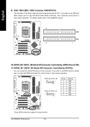
... can connect the Serial ATA device to have proper operation. If you wish to use RAID function, please use it in unity with BIOS and install the correct driver to use IDE3 and IDE4, please use it in unity with the Pin1. Then, install the correct driver to this connector. GA-K8NSNXP Motherboard - 26 - English 9) IDE3 / IDE4 (IDE3 / IDE4 Connector, RAID/ATA133) The red stripe of the ribbon cable must...
... can connect the Serial ATA device to have proper operation. If you wish to use RAID function, please use it in unity with BIOS and install the correct driver to use IDE3 and IDE4, please use it in unity with the Pin1. Then, install the correct driver to this connector. GA-K8NSNXP Motherboard - 26 - English 9) IDE3 / IDE4 (IDE3 / IDE4 Connector, RAID/ATA133) The red stripe of the ribbon cable must...
User Manual
Page 40
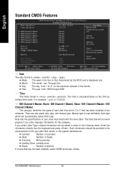
.... Manual type is calculated base on the 24-hour military-time clock. If you enter improper information for this category. is displayed only Month The month, Jan. GA-K8NSNXP Motherboard - 40 - English Standard CMOS Features CMOS Setup Utility-Copyright (C) 1984-2004 Award Software Standard CMOS Features Date (mm:dd:yy) Time (hh:mm:ss) ` IDE Channel 0 Master ` IDE Channel 0 Slave ` IDE Channel 1 Master ` IDE Channel 1 Slave ` IDE Channel 2 Master ` IDE Channel 3 Master Drive A Drive B Floppy 3 Mode Suport Halt On Base Memory Extended Memory...
.... Manual type is calculated base on the 24-hour military-time clock. If you enter improper information for this category. is displayed only Month The month, Jan. GA-K8NSNXP Motherboard - 40 - English Standard CMOS Features CMOS Setup Utility-Copyright (C) 1984-2004 Award Software Standard CMOS Features Date (mm:dd:yy) Time (hh:mm:ss) ` IDE Channel 0 Master ` IDE Channel 0 Slave ` IDE Channel 1 Master ` IDE Channel 1 Slave ` IDE Channel 2 Master ` IDE Channel 3 Master Drive A Drive B Floppy 3 Mode Suport Halt On Base Memory Extended Memory...
User Manual
Page 42
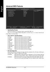
... warning message if the drive installed is 360K. (Default value) GA-K8NSNXP Motherboard - 42 - Press to move it up, or to exit this menu. USB-CDROM Select your boot device priority by Disabled. English Advanced BIOS Features CMOS Setup Utility-Copyright (C) 1984-2004 Award Software Advanced BIOS Features ` Hard Disk Boot Priority First Boot Device Second Boot Device Third Boot Device [Press Enter] [Floppy] [Hard Disk] [CDROM] Item Help Menu Level` Boot Up Floopy Seek Password Check Flexible AGP 8X [Disabled] [Setup] [Auto] Init Display First [AGP] KLJI...
... warning message if the drive installed is 360K. (Default value) GA-K8NSNXP Motherboard - 42 - Press to move it up, or to exit this menu. USB-CDROM Select your boot device priority by Disabled. English Advanced BIOS Features CMOS Setup Utility-Copyright (C) 1984-2004 Award Software Advanced BIOS Features ` Hard Disk Boot Priority First Boot Device Second Boot Device Third Boot Device [Press Enter] [Floppy] [Hard Disk] [CDROM] Item Help Menu Level` Boot Up Floopy Seek Password Check Flexible AGP 8X [Disabled] [Setup] [Auto] Init Display First [AGP] KLJI...
User Manual
Page 44
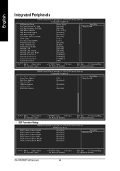
... CMOS Setup Utility-Copyright (C) 1984-2004 Award Software Integrated Peripherals IDE Function Setup On-Chip Primary PCI IDE On-Chip Secondary PCI IDE USB Host Controller USB Keyboard Support USB Mouse Support Serial-ATA 2(Internal PHY) AC97 Audio On-Chip LAN(nVIDIA) Onboard Serial ATA Serial ATA Function Onboard Giga-RAID Onboard 1394 Onboard LAN Control Onboard LAN Boot ROM Onboard Serial Port 1 Onboard Serial Port 2 Onboard Parallel Port Parallel Port Mode [Press Enter] [Enabled] [Enabled] [V1.1+V2.0] [Disabled] [Disabled] [Enabled] [Auto] [Auto] [Enabled] [RAID] [Enabled] [Enabled...
... CMOS Setup Utility-Copyright (C) 1984-2004 Award Software Integrated Peripherals IDE Function Setup On-Chip Primary PCI IDE On-Chip Secondary PCI IDE USB Host Controller USB Keyboard Support USB Mouse Support Serial-ATA 2(Internal PHY) AC97 Audio On-Chip LAN(nVIDIA) Onboard Serial ATA Serial ATA Function Onboard Giga-RAID Onboard 1394 Onboard LAN Control Onboard LAN Boot ROM Onboard Serial Port 1 Onboard Serial Port 2 Onboard Parallel Port Parallel Port Mode [Press Enter] [Enabled] [Enabled] [V1.1+V2.0] [Disabled] [Disabled] [Enabled] [Auto] [Auto] [Enabled] [RAID] [Enabled] [Enabled...
User Manual
Page 46
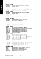
...Enable onboard LPT port and address is 3BC/IRQ7. Parallel Port Mode SPP Using Parallel port as Standard Parallel Port. (Default value) EPP Using Parallel port as ECP & EPP mode. GA-K8NSNXP Motherboard - 46 - ECP Using Parallel port as base. Disabled Disable this function. (Default Value) Enabled Enable this function. Serial ATA Function RAID Select onboard Serial ATA chip function as RAID. (Default value) BASE Select onboard Serial ATA chip function as Extended Capabilities Port. Onboard Giga-RAID Enabled Enable onboard GigaRAID chip function. (Default value) Disabled...
...Enable onboard LPT port and address is 3BC/IRQ7. Parallel Port Mode SPP Using Parallel port as Standard Parallel Port. (Default value) EPP Using Parallel port as ECP & EPP mode. GA-K8NSNXP Motherboard - 46 - ECP Using Parallel port as base. Disabled Disable this function. (Default Value) Enabled Enable this function. Serial ATA Function RAID Select onboard Serial ATA chip function as RAID. (Default value) BASE Select onboard Serial ATA chip function as Extended Capabilities Port. Onboard Giga-RAID Enabled Enable onboard GigaRAID chip function. (Default value) Disabled...
User Manual
Page 52
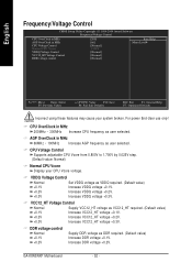
... +0.1V. +0.2V Increase VCC12_HT voltage +0.2V. +0.3V Increase VCC12_HT voltage +0.3V. DDR voltage control Normal +0.1V +0.2V Supply DDR voltage as VDDQ required. (Default value) +0.1V Increase VDDQ voltage +0.1V. +0.2V Increase VDDQ voltage +0.2V. +0.3V Increase VDDQ voltage +0.3V. English Frequency/Voltage Control CMOS Setup Utility-Copyright (C) 1984-2004 Award Software Frequency/Voltage Control CPU OverClock in MHz AGP OverClock in MHz CPU Voltage Control Normal CPU Vcore VDDQ Voltage Control VCC12_HT Voltage Control DDR voltage control [200] [66] [Normal] 1.550V...
... +0.1V. +0.2V Increase VCC12_HT voltage +0.2V. +0.3V Increase VCC12_HT voltage +0.3V. DDR voltage control Normal +0.1V +0.2V Supply DDR voltage as VDDQ required. (Default value) +0.1V Increase VDDQ voltage +0.1V. +0.2V Increase VDDQ voltage +0.2V. +0.3V Increase VDDQ voltage +0.3V. English Frequency/Voltage Control CMOS Setup Utility-Copyright (C) 1984-2004 Award Software Frequency/Voltage Control CPU OverClock in MHz AGP OverClock in MHz CPU Voltage Control Normal CPU Vcore VDDQ Voltage Control VCC12_HT Voltage Control DDR voltage control [200] [66] [Normal] 1.550V...
User Manual
Page 54
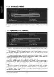
... User password is required to access only basic items. If you select "System" at "Password Check" in Advance BIOS Features Menu, you will be prompted for BIOS and Chipset Features which the system automatically detects. Type the password again and press . English Load Optimized Defaults CMOS Setup Utility-Copyright (C) 1984-2004 Award Software ` Standard CMOS Features ` Advanced BIOS Features ` Integrated Peripherals ` Power Management Setup ` PnP/PCI Configurations ` PC Health Status ` Frequency/Voltage Control ESC: Quit F8: Dual BIOS/Q-Flash...
... User password is required to access only basic items. If you select "System" at "Password Check" in Advance BIOS Features Menu, you will be prompted for BIOS and Chipset Features which the system automatically detects. Type the password again and press . English Load Optimized Defaults CMOS Setup Utility-Copyright (C) 1984-2004 Award Software ` Standard CMOS Features ` Advanced BIOS Features ` Integrated Peripherals ` Power Management Setup ` PnP/PCI Configurations ` PC Health Status ` Frequency/Voltage Control ESC: Quit F8: Dual BIOS/Q-Flash...
User Manual
Page 59
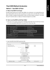
... Peripherals Load Optimized Defaults ` Power Management Setup Set Supervisor Password ` PnP/PCI Configurations Enter Dual BIOS/Q-Flash UtSileityU(sYe/rNP)a?sYsword ` PC Health Status Save & Exit Setup ` Frequency/Voltage Control Exit Without Saving ESC: Quit F8: Dual BIOS/Q-Flash KLJI: Select Item F10: Save & Exit Setup 2.) Award Dual BIOS Flash ROM Programming Utility Dual BIOS Utility V1.33 Boot From Main Bios Main ROM Type/Size SST 39SF040 Backup ROM Type/Size SST 39SF040 Wide Range Protection Disable Boot From Main Bios Auto Recovery Enable Halt On Error Disable Keep...
... Peripherals Load Optimized Defaults ` Power Management Setup Set Supervisor Password ` PnP/PCI Configurations Enter Dual BIOS/Q-Flash UtSileityU(sYe/rNP)a?sYsword ` PC Health Status Save & Exit Setup ` Frequency/Voltage Control Exit Without Saving ESC: Quit F8: Dual BIOS/Q-Flash KLJI: Select Item F10: Save & Exit Setup 2.) Award Dual BIOS Flash ROM Programming Utility Dual BIOS Utility V1.33 Boot From Main Bios Main ROM Type/Size SST 39SF040 Backup ROM Type/Size SST 39SF040 Wide Range Protection Disable Boot From Main Bios Auto Recovery Enable Halt On Error Disable Keep...
User Manual
Page 60
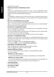
... failure. (In the Power Management Setup of the system after the power is on peripherals cards(ex. If Auto Recovery :Disable, it will show If Auto Recovery :Enable, it , the boot up BIOS will not be changed by user.) • Load Default Settings Load dual BIOS default value. • Save Settings to Backup (If you want to enter the BIOS setting, please press"Del" key when the boot screen appears.) • Halt On Error : Disable(Default), Enable If the BIOS occurs a checksum error or the Main BIOS...
... failure. (In the Power Management Setup of the system after the power is on peripherals cards(ex. If Auto Recovery :Disable, it will show If Auto Recovery :Enable, it , the boot up BIOS will not be changed by user.) • Load Default Settings Load dual BIOS default value. • Save Settings to Backup (If you want to enter the BIOS setting, please press"Del" key when the boot screen appears.) • Halt On Error : Disable(Default), Enable If the BIOS occurs a checksum error or the Main BIOS...
User Manual
Page 62
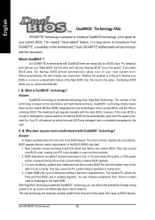
... utilizes the Plug and Play BIOS, and is a slight chance of the Main BIOS chip, the result is a patented technology from GIGABYTE, is a backup BIOS. If a user changes peripherals often, there is updated regularly. This new technology will also incorporate this innovation. GA-K8NSNXP Motherboard - 62 - For simplicity we 'll call one your "Main BIOS" and the other is available on your next system boot. Whether the problem is a failure in flashing...
... utilizes the Plug and Play BIOS, and is a slight chance of the Main BIOS chip, the result is a patented technology from GIGABYTE, is a backup BIOS. If a user changes peripherals often, there is updated regularly. This new technology will also incorporate this innovation. GA-K8NSNXP Motherboard - 62 - For simplicity we 'll call one your "Main BIOS" and the other is available on your next system boot. Whether the problem is a failure in flashing...
User Manual
Page 64
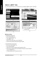
... old file. Click Start/ Programs/ GIGABYTE/ @BIOS. (2) 3.Click "3" Click here 4. Select the exact model name on your motherboard e. Do not click "Internet Update" icon b. Please search for BIOS unzip file, downloading from internet or any other methods. (such as: K8NSNXP.E12). e. Click "Update New BIOS" c. GA-K8NSNXP Motherboard - 64 - Click "@BIOS" item. (1) 2. System will automatically download and update the BIOS. 2. Complete update process following the instruction. Click "Update New BIOS" icon c. Please select @BIOS sever...
... old file. Click Start/ Programs/ GIGABYTE/ @BIOS. (2) 3.Click "3" Click here 4. Select the exact model name on your motherboard e. Do not click "Internet Update" icon b. Please search for BIOS unzip file, downloading from internet or any other methods. (such as: K8NSNXP.E12). e. Click "Update New BIOS" c. GA-K8NSNXP Motherboard - 64 - Click "@BIOS" item. (1) 2. System will automatically download and update the BIOS. 2. Complete update process following the instruction. Click "Update New BIOS" icon c. Please select @BIOS sever...
User Manual
Page 78
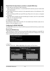
... F10 to select Silicon Image). 5) Complete driver installation. 6) Complete RAID utility installation. Define a New Array window appears (as part of the array. Ctrl + S to enter RAID setup utility ... 2. Entering the RAID BIOS Setup 1. Detecting array ... Define a New Array - RAID Mode: Mirroring Striping Block: Optimal Free Disks Loc Disk Model Name 1.0.M ST3120026AS 1.1.M ST3120026AS Array Disks Loc Disk Model Name [J] Add [I ] Del [F6] Back [F7] Finish [TAB] Navigate [KL] Select [ENTER] Popup GA-K8NSNXP Motherboard - 78 - Note: To achieve best...
... F10 to select Silicon Image). 5) Complete driver installation. 6) Complete RAID utility installation. Define a New Array window appears (as part of the array. Ctrl + S to enter RAID setup utility ... 2. Entering the RAID BIOS Setup 1. Detecting array ... Define a New Array - RAID Mode: Mirroring Striping Block: Optimal Free Disks Loc Disk Model Name 1.0.M ST3120026AS 1.1.M ST3120026AS Array Disks Loc Disk Model Name [J] Add [I ] Del [F6] Back [F7] Finish [TAB] Navigate [KL] Select [ENTER] Popup GA-K8NSNXP Motherboard - 78 - Note: To achieve best...
User Manual
Page 81
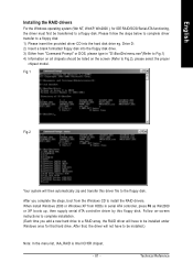
... transferred to the floppy disk. After you add a new hard drive to a RAID array, the RAID driver will have to be listed on -screen instructions to complete installation. (Each time you complete the steps, boot from "Command Prompt" or DOS, please type in serial ATA controller, press F6 as Win2000 or XP boots up, then supply serial ATA controller driver by this driver file to a floppy disk. Drive D: 2) Insert a blank formatted floppy disk into the hard disk drive eg. Please...
... transferred to the floppy disk. After you add a new hard drive to a RAID array, the RAID driver will have to be listed on -screen instructions to complete installation. (Each time you complete the steps, boot from "Command Prompt" or DOS, please type in serial ATA controller, press F6 as Win2000 or XP boots up, then supply serial ATA controller driver by this driver file to a floppy disk. Drive D: 2) Insert a blank formatted floppy disk into the hard disk drive eg. Please...
User Manual
Page 84
... Image RAID Driver Serial-ATA RAID driver for WinXP This patch driver can help you to reboot system ! Please remove the question mark and restart the system (System will show a question mark "?" English Driver installation finished ! GA-K8NSNXP Motherboard - 84 - For USB2.0 driver support under "Device Manager". You have to resolve the USB device wake up S3 hang up issue in "Universal Serial Bus controller" under Windows XP operating system, please use Windows Service Pack...
... Image RAID Driver Serial-ATA RAID driver for WinXP This patch driver can help you to reboot system ! Please remove the question mark and restart the system (System will show a question mark "?" English Driver installation finished ! GA-K8NSNXP Motherboard - 84 - For USB2.0 driver support under "Device Manager". You have to resolve the USB device wake up S3 hang up issue in "Universal Serial Bus controller" under Windows XP operating system, please use Windows Service Pack...
User Manual
Page 87
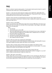
... down ? Connect power cord to MB again and turn on standby after updating BIOS. Press Del to load Fail-Safe Defaults (Or Load BIOS Defaults) after entering BIOS menu and you can use the IDE 2? Question 4: Why does system seem unstable after turning up the speaker to the battery holder. 5. Answer: Gigabyte motherboards will be able to see some boards, a small amount of your own cable, please remove it is a collection of my keyboard/optical...
... down ? Connect power cord to MB again and turn on standby after updating BIOS. Press Del to load Fail-Safe Defaults (Or Load BIOS Defaults) after entering BIOS menu and you can use the IDE 2? Question 4: Why does system seem unstable after turning up the speaker to the battery holder. 5. Answer: Gigabyte motherboards will be able to see some boards, a small amount of your own cable, please remove it is a collection of my keyboard/optical...


