Manual
Page 3
...Motherboard Revision The revision number on how to assist in the use GIGABYTE's unique features, read the User's Manual. For instructions on your motherboard revision before updating motherboard BIOS, drivers, or when looking for technical information. Copyright © 2008... GIGA-BYTE TECHNOLOGY CO., LTD. All rights reserved. Documentation Classifications In order to use of this product, GIGABYTE provides the following types of documentations:...
...Motherboard Revision The revision number on how to assist in the use GIGABYTE's unique features, read the User's Manual. For instructions on your motherboard revision before updating motherboard BIOS, drivers, or when looking for technical information. Copyright © 2008... GIGA-BYTE TECHNOLOGY CO., LTD. All rights reserved. Documentation Classifications In order to use of this product, GIGABYTE provides the following types of documentations:...
Manual
Page 4
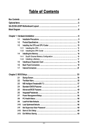
Table of Contents Box Contents ...6 OptionalItems ...6 GA-EX58-UD3R Motherboard Layout 7 Block Diagram ...8 Chapter 1 Hardware Installation 9 1-1 Installation Precautions 9 1-2 Product Specifications 10 1-3 Installing the CPU and CPU Cooler ... Installing an Expansion Card 18 1-6 Back Panel Connectors 19 1-7 Internal Connectors 21 Chapter 2 BIOS Setup 33 2-1 Startup Screen 34 2-2 The Main Menu 35 2-3 MB Intelligent Tweaker(M.I.T 37 2-4 Standard CMOS Features 47 2-5 Advanced BIOS Features 49 2-6 IntegratedPeripherals 51 2-7 Power Management Setup 54 2-8 PC Health Status 56 2-9 ...
Table of Contents Box Contents ...6 OptionalItems ...6 GA-EX58-UD3R Motherboard Layout 7 Block Diagram ...8 Chapter 1 Hardware Installation 9 1-1 Installation Precautions 9 1-2 Product Specifications 10 1-3 Installing the CPU and CPU Cooler ... Installing an Expansion Card 18 1-6 Back Panel Connectors 19 1-7 Internal Connectors 21 Chapter 2 BIOS Setup 33 2-1 Startup Screen 34 2-2 The Main Menu 35 2-3 MB Intelligent Tweaker(M.I.T 37 2-4 Standard CMOS Features 47 2-5 Advanced BIOS Features 49 2-6 IntegratedPeripherals 51 2-7 Power Management Setup 54 2-8 PC Health Status 56 2-9 ...

Manual
Page 5
... Download Center 64 Chapter 4 Unique Features 65 4-1 Xpress Recovery2 65 4-2 BIOS Update Utilities 68 4-2-1 Updating the BIOS with the Q-Flash Utility 68 4-2-2 Updating the BIOS with the @BIOS Utility 71 4-3 EasyTune 6 ...72 4-4 Dynamic Energy Saver Advanced 73 4-5 ...Q-Share ...75 4-6 Time Repair ...76 Chapter 5 Appendix ...77 5-1 Configuring SATA Hard Drive(s 77 5-1-1 Configuring Intel ICH10R SATA Controllers 77 5-1-2 Configuring GIGABYTE...
... Download Center 64 Chapter 4 Unique Features 65 4-1 Xpress Recovery2 65 4-2 BIOS Update Utilities 68 4-2-1 Updating the BIOS with the Q-Flash Utility 68 4-2-2 Updating the BIOS with the @BIOS Utility 71 4-3 EasyTune 6 ...72 4-4 Dynamic Energy Saver Advanced 73 4-5 ...Q-Share ...75 4-6 Time Repair ...76 Chapter 5 Appendix ...77 5-1 Configuring SATA Hard Drive(s 77 5-1-1 Configuring Intel ICH10R SATA Controllers 77 5-1-2 Configuring GIGABYTE...

Manual
Page 8
... CLK (100 MHz) x1 x1 PCI Express Bus 2 SATA 3Gb/s ATA-133/100/66/33 IDE Channel PCI Bus LAN RJ45 RTL 8111D x1 x1 GIGABYTE SATA2 TSB43AB23 LGA1366 Processor CPU CLK+/- (133 MHz) DDR3 2000/1333/1066/800 MHz Dual/3 Channel Memory QPI Interface Intel® X58 IOH CLK (133... MHz) Intel® ICH10R Dual BIOS 6 SATA 3Gb/s 12 USB Ports LPC Bus IT8720 Floppy COM Port 3 IEEE 1394a CODEC PS/2 KB/Mouse Surround Speaker Out Center/Subwoofer Speaker Out Side...
... CLK (100 MHz) x1 x1 PCI Express Bus 2 SATA 3Gb/s ATA-133/100/66/33 IDE Channel PCI Bus LAN RJ45 RTL 8111D x1 x1 GIGABYTE SATA2 TSB43AB23 LGA1366 Processor CPU CLK+/- (133 MHz) DDR3 2000/1333/1066/800 MHz Dual/3 Channel Memory QPI Interface Intel® X58 IOH CLK (133... MHz) Intel® ICH10R Dual BIOS 6 SATA 3Gb/s 12 USB Ports LPC Bus IT8720 Floppy COM Port 3 IEEE 1394a CODEC PS/2 KB/Mouse Surround Speaker Out Center/Subwoofer Speaker Out Side...
Manual
Page 12
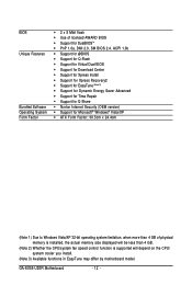
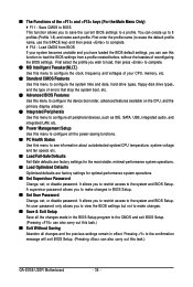
... Software Operating System Form Factor 2 x 8 Mbit flash Use of licensed AWARD BIOS Support for DualBIOSTM PnP 1.0a, DMI 2.0, SM BIOS 2.4, ACPI 1.0b Support for @BIOS Support for Q-Flash Support for Virtual Dual BIOS Support for Download Center Support for Xpress Install Support for Xpress... fan speed control function is supported will depend on the CPU/ system cooler you install. (Note 3) Available functions in EasyTune may differ by motherboard model. GA-EX58-UD3R Motherboard - 12 -
... Software Operating System Form Factor 2 x 8 Mbit flash Use of licensed AWARD BIOS Support for DualBIOSTM PnP 1.0a, DMI 2.0, SM BIOS 2.4, ACPI 1.0b Support for @BIOS Support for Q-Flash Support for Virtual Dual BIOS Support for Download Center Support for Xpress Install Support for Xpress... fan speed control function is supported will depend on the CPU/ system cooler you install. (Note 3) Available functions in EasyTune may differ by motherboard model. GA-EX58-UD3R Motherboard - 12 -
Manual
Page 16
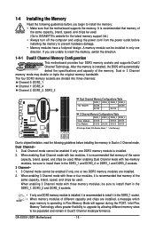
...GA-EX58-UD3R Motherboard - 16 - After the memory is installed. 2. DS/SS - - 3 Channel Memory Configurations Table DDR3_1 DDR3_3 DDR3_2 DDR3_4 Three Modules DS/SS - - When enabling 3 Channel mode with two modules, it in the DDR3_1 socket. • When memory modules of the same capacity, brand, speed, and chips be used . (Go to GIGABYTE... Dual or 3 Channel mode. If you begin to be enabled if only one DDR3 memory module is installed, the BIOS will appear during the POST. Dual Channel-1. It is operating in Flex Memory Mode will automatically detect the specifications and ...
...GA-EX58-UD3R Motherboard - 16 - After the memory is installed. 2. DS/SS - - 3 Channel Memory Configurations Table DDR3_1 DDR3_3 DDR3_2 DDR3_4 Three Modules DS/SS - - When enabling 3 Channel mode with two modules, it in the DDR3_1 socket. • When memory modules of the same capacity, brand, speed, and chips be used . (Go to GIGABYTE... Dual or 3 Channel mode. If you begin to be enabled if only one DDR3 memory module is installed, the BIOS will appear during the POST. Dual Channel-1. It is operating in Flex Memory Mode will automatically detect the specifications and ...
Manual
Page 18
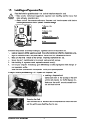
PCI Express x1 Slot PCI Express x4 Slot PCI Express x16 Slot PCI Slot Follow the steps below to make any required BIOS changes for your operating system. Align the card with the expansion card in your expansion card(s). 7. Make sure the metal contacts...Graphics Card: Gently push down on the card are completely inserted into the PCI Express slot. GA-EX58-UD3R Motherboard - 18 - Make sure the card is fully inserted into the slot. 4. If necessary, go to BIOS Setup to correctly install your computer. 1-5 Installing an Expansion Card Read the following guidelines before ...
PCI Express x1 Slot PCI Express x4 Slot PCI Express x16 Slot PCI Slot Follow the steps below to make any required BIOS changes for your operating system. Align the card with the expansion card in your expansion card(s). 7. Make sure the metal contacts...Graphics Card: Gently push down on the card are completely inserted into the PCI Express slot. GA-EX58-UD3R Motherboard - 18 - Make sure the card is fully inserted into the slot. 4. If necessary, go to BIOS Setup to correctly install your computer. 1-5 Installing an Expansion Card Read the following guidelines before ...
Manual
Page 26
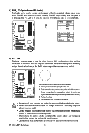
... LED S0 On S1 Blinking S3/S4/S5 Off 12) BATTERY The battery provides power to keep the values (such as BIOS configurations, date, and time information) in S1 sleep state. GA-EX58-UD3R Motherboard - 26 - Replace the battery when the battery voltage drops to replace the battery by removing the battery: 1. Gently remove...
... LED S0 On S1 Blinking S3/S4/S5 Off 12) BATTERY The battery provides power to keep the values (such as BIOS configurations, date, and time information) in S1 sleep state. GA-EX58-UD3R Motherboard - 26 - Replace the battery when the battery voltage drops to replace the battery by removing the battery: 1. Gently remove...
Manual
Page 27
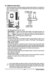
... switch, reset switch, speaker and system status indicator on the chassis front panel. The LED is on when the hard drive is detected, the BIOS may configure the way to turn off (S5). • PW (Power Switch, Red): Connects to the power switch on the chassis front panel.... When connecting your system using the power switch (refer to Chapter 2, "BIOS Setup," "Power Management Setup," for information about beep codes. • HD (Hard Drive Activity LED, Blue) Connects to the pin assignments below. Message/...
... switch, reset switch, speaker and system status indicator on the chassis front panel. The LED is on when the hard drive is detected, the BIOS may configure the way to turn off (S5). • PW (Power Switch, Red): Connects to the power switch on the chassis front panel.... When connecting your system using the power switch (refer to Chapter 2, "BIOS Setup," "Power Management Setup," for information about beep codes. • HD (Hard Drive Activity LED, Blue) Connects to the pin assignments below. Message/...
Manual
Page 32
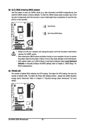
... (refer to remove the jumper cap from the jumper. Refer to touch the two pins for BIOS configurations). 23) PHASE LED The number of lighted LEDs. Open: Normal Short: Clear CMOS Values • Always turn off your computer and unplug the .... To enable the Phase LED display function, please first enable Dynamic Energy Saver Advanced. The higher the CPU loading, the more details. GA-EX58-UD3R Motherboard - 32 - 22) CLR_CMOS (Clearing CMOS Jumper) Use this jumper to factory defaults. date information and BIOS configurations) and reset the CMOS values to clear the CMOS values (e.g.
... (refer to remove the jumper cap from the jumper. Refer to touch the two pins for BIOS configurations). 23) PHASE LED The number of lighted LEDs. Open: Normal Short: Clear CMOS Values • Always turn off your computer and unplug the .... To enable the Phase LED display function, please first enable Dynamic Energy Saver Advanced. The higher the CPU loading, the more details. GA-EX58-UD3R Motherboard - 32 - 22) CLR_CMOS (Clearing CMOS Jumper) Use this jumper to factory defaults. date information and BIOS configurations) and reset the CMOS values to clear the CMOS values (e.g.

Manual
Page 33
...the configuration values in system's failure to Chapter 4, "BIOS Update Utilities." • Because BIOS flashing is a Windows-based utility that you need to) to activate certain system features. To upgrade the BIOS, use either the GIGABYTE Q-Flash or @BIOS utility. • Q-Flash allows the user to ...quickly and easily upgrade or back up BIOS without entering the operating system. • @BIOS is potentially risky, if you can press + in...
...the configuration values in system's failure to Chapter 4, "BIOS Update Utilities." • Because BIOS flashing is a Windows-based utility that you need to) to activate certain system features. To upgrade the BIOS, use either the GIGABYTE Q-Flash or @BIOS utility. • Q-Flash allows the user to ...quickly and easily upgrade or back up BIOS without entering the operating system. • @BIOS is potentially risky, if you can press + in...

Manual
Page 34
...Boot Menu, press . GA-EX58-UD3R Motherboard - 34 - To show the BIOS POST screen. Note: The setting in Boot Menu. You can be based on page 50. : BIOS SETUP\Q-FLASH Press the key to enter BIOS Setup or to access the Q-Flash utility in BIOS Setup. : XPRESS ...instructions on the Full Screen LOGO Show item on BIOS Setup settings. The POST Screen Function Keys Motherboard Model BIOS Version Award Modular BIOS v6.00PG, An Energy Star Ally Copyright (C) 1984-2008, Award Software, Inc. A. EX58-UD3R F1b . . . . : BIOS Setup : XpressRecovery2 : Boot Menu : Qflash 11...
...Boot Menu, press . GA-EX58-UD3R Motherboard - 34 - To show the BIOS POST screen. Note: The setting in Boot Menu. You can be based on page 50. : BIOS SETUP\Q-FLASH Press the key to enter BIOS Setup or to access the Q-Flash utility in BIOS Setup. : XPRESS ...instructions on the Full Screen LOGO Show item on BIOS Setup settings. The POST Screen Function Keys Motherboard Model BIOS Version Award Modular BIOS v6.00PG, An Energy Star Ally Copyright (C) 1984-2008, Award Software, Inc. A. EX58-UD3R F1b . . . . : BIOS Setup : XpressRecovery2 : Boot Menu : Qflash 11...
Manual
Page 35
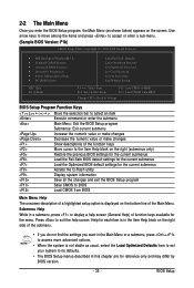
... current submenus Access the Q-Flash utility Display system information Save all the changes and exit the BIOS Setup program Save CMOS to BIOS Load CMOS from BIOS Change CPU's Clock & Voltage BIOS Setup Program Function Keys Move the selection bar to display a help screen. Help for each ...item is in a submenu, press to select an item Execute command or enter the submenu Main Menu: Exit the BIOS Setup program Submenus: Exit current submenu Increase the numeric value or make changes Decrease the numeric value or make changes Show descriptions of...
... current submenus Access the Q-Flash utility Display system information Save all the changes and exit the BIOS Setup program Save CMOS to BIOS Load CMOS from BIOS Change CPU's Clock & Voltage BIOS Setup Program Function Keys Move the selection bar to display a help screen. Help for each ...item is in a submenu, press to select an item Execute command or enter the submenu Main Menu: Exit the BIOS Setup program Submenus: Exit current submenu Increase the numeric value or make changes Decrease the numeric value or make changes Show descriptions of...
Manual
Page 36
... the changes made in the BIOS Setup program to the CMOS and exit BIOS Setup. (Pressing can create up to 8 profiles (Profile 1-8) and name each profile. It allows you to restrict access to the system and BIOS Setup. You can also carry out this task.) GA-EX58-UD3R Motherboard - 36 - First ...enter the profile name (to erase the default profile name, use this function to load the BIOS settings from BIOS If your CPU, memory, etc. Standard ...
... the changes made in the BIOS Setup program to the CMOS and exit BIOS Setup. (Pressing can create up to 8 profiles (Profile 1-8) and name each profile. It allows you to restrict access to the system and BIOS Setup. You can also carry out this task.) GA-EX58-UD3R Motherboard - 36 - First ...enter the profile name (to erase the default profile name, use this function to load the BIOS settings from BIOS If your CPU, memory, etc. Standard ...
Manual
Page 37
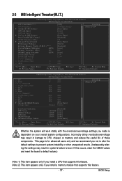
... in system's failure to CPU, chipset, or memory and reduce the useful life of these components. This page is dependent on your overall system configurations. BIOS Setup 2-3 MB Intelligent Tweaker(M.I.T.) CMOS Setup Utility-Copyright (C) 1984-2008 Award Software MB Intelligent Tweaker(M.I.T.) CPU Clock Ratio (Note 1) CPU Frequency Advanced CPU Features...
... in system's failure to CPU, chipset, or memory and reduce the useful life of these components. This page is dependent on your overall system configurations. BIOS Setup 2-3 MB Intelligent Tweaker(M.I.T.) CMOS Setup Utility-Copyright (C) 1984-2008 Award Software MB Intelligent Tweaker(M.I.T.) CPU Clock Ratio (Note 1) CPU Frequency Advanced CPU Features...

Manual
Page 39
... be emitted to lower CPU performance to decrease heat production. (Default) Only allows the CPU to run multiple operating systems and applications in independent partitions. BIOS Setup
... be emitted to lower CPU performance to decrease heat production. (Default) Only allows the CPU to run multiple operating systems and applications in independent partitions. BIOS Setup

Manual
Page 41
... read the SPD data on XMP memory module(s) to adjust the amplitude of the CPU and North Bridge clock. BIOS Setup Options are : 700mV, 800mV (default), 900mV, 1000mV. Options are : 0ps~750ps. (Default: 0ps) ******* Advanced DRAM Features ******* CMOS Setup Utility-Copyright (C) 1984-2008 Award Software ...
... read the SPD data on XMP memory module(s) to adjust the amplitude of the CPU and North Bridge clock. BIOS Setup Options are : 700mV, 800mV (default), 900mV, 1000mV. Options are : 0ps~750ps. (Default: 0ps) ******* Advanced DRAM Features ******* CMOS Setup Utility-Copyright (C) 1984-2008 Award Software ...
Manual
Page 43
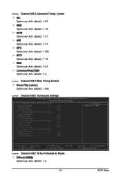
tWTR Options are : Auto (default), 1~255. ESC: Exit F1: General Help F7: Optimized Defaults - 43 - BIOS Setup tRFC Options are : Auto (default), 1~31. Command Rate(CMD) Options are: Auto (default), 1~2. >>>>> Channel A/B/C Misc Timing Control Round Trip Latency Options are: Auto (default), 1~...
tWTR Options are : Auto (default), 1~255. ESC: Exit F1: General Help F7: Optimized Defaults - 43 - BIOS Setup tRFC Options are : Auto (default), 1~31. Command Rate(CMD) Options are: Auto (default), 1~2. >>>>> Channel A/B/C Misc Timing Control Round Trip Latency Options are: Auto (default), 1~...
Manual
Page 45
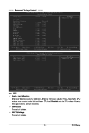
... more constant under light and heavy CPU load. Disabled sets the CPU voltage following Intel specifications. (Default: Disabled) CPU Vcore The default is Auto. - 45 - BIOS Setup Ch-B Address VRef. Ch-C Address VRef. 0.750V 0.750V 0.750V [Auto] [Auto] [Auto] Item Help Menu Level Move Enter: Select F5: Previous...
... more constant under light and heavy CPU load. Disabled sets the CPU voltage following Intel specifications. (Default: Disabled) CPU Vcore The default is Auto. - 45 - BIOS Setup Ch-B Address VRef. Ch-C Address VRef. 0.750V 0.750V 0.750V [Auto] [Auto] [Auto] Item Help Menu Level Move Enter: Select F5: Previous...
Manual
Page 47
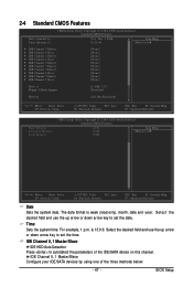
Select the desired field and use the up arrow or down arrow key to autodetect the parameters of the three methods below: - 47 - BIOS Setup IDE Channel 0, 1 Master/Slave Configure your IDE/SATA devices by using one of the IDE/SATA device on this channel. Time Sets the system ...
Select the desired field and use the up arrow or down arrow key to autodetect the parameters of the three methods below: - 47 - BIOS Setup IDE Channel 0, 1 Master/Slave Configure your IDE/SATA devices by using one of the IDE/SATA device on this channel. Time Sets the system ...


