Manual
Page 4
... CPU 13 1-3-2 Installing the CPU Cooler 15 1-4 Installing the Memory 16 1-4-1 Dual/3 Channel Memory Configuration 16 1-4-2 Installing a Memory 17 1-5 Installing an Expansion Card 18 1-6 Back Panel Connectors 19 1-7 Internal Connectors 21 Chapter 2 BIOS Setup 33 2-1 Startup Screen 34 2-2 The Main Menu 35 2-3 MB Intelligent Tweaker(M.I.T 37 2-4 Standard CMOS Features 47 2-5 Advanced BIOS Features 49 2-6 IntegratedPeripherals 51 2-7 Power Management Setup 54 2-8 PC Health Status 56 2-9 Load Fail-Safe Defaults 58 2-10 Load Optimized Defaults 58 2-11 Set Supervisor/User Password...
... CPU 13 1-3-2 Installing the CPU Cooler 15 1-4 Installing the Memory 16 1-4-1 Dual/3 Channel Memory Configuration 16 1-4-2 Installing a Memory 17 1-5 Installing an Expansion Card 18 1-6 Back Panel Connectors 19 1-7 Internal Connectors 21 Chapter 2 BIOS Setup 33 2-1 Startup Screen 34 2-2 The Main Menu 35 2-3 MB Intelligent Tweaker(M.I.T 37 2-4 Standard CMOS Features 47 2-5 Advanced BIOS Features 49 2-6 IntegratedPeripherals 51 2-7 Power Management Setup 54 2-8 PC Health Status 56 2-9 Load Fail-Safe Defaults 58 2-10 Load Optimized Defaults 58 2-11 Set Supervisor/User Password...
Manual
Page 10
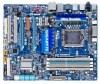
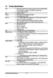
... 2 SATA 3Gb/s devices - Support for SATA RAID 0, RAID 1, RAID 5, and RAID 10 GIGABYTE SATA2 chip: - 1 x IDE connector supporting ATA-133/100/66/33 and up to 2 IDE devices - 2 x SATA 3Gb/s connectors (GSATA2_0, GSATA2_1) supporting up to 6 SATA 3Gb/s devices - 1-2 Product Specifications CPU QPI Chipset Memory Audio LAN Expansion Slots Storage Interface USB IEEE 1394 Support for an Intel® CoreTM i7 series processor in the South Bridge Up to 12 USB 2.0/1.1 ports (8 on the back panel, 1 via the USB brackets connected to the internal USB headers) ...
... 2 SATA 3Gb/s devices - Support for SATA RAID 0, RAID 1, RAID 5, and RAID 10 GIGABYTE SATA2 chip: - 1 x IDE connector supporting ATA-133/100/66/33 and up to 2 IDE devices - 2 x SATA 3Gb/s connectors (GSATA2_0, GSATA2_1) supporting up to 6 SATA 3Gb/s devices - 1-2 Product Specifications CPU QPI Chipset Memory Audio LAN Expansion Slots Storage Interface USB IEEE 1394 Support for an Intel® CoreTM i7 series processor in the South Bridge Up to 12 USB 2.0/1.1 ports (8 on the back panel, 1 via the USB brackets connected to the internal USB headers) ...
Manual
Page 16
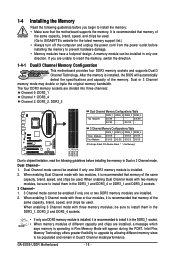
... same capacity, brand, speed, and chips be used. After the memory is installed. 2. Dual or 3 Channel memory mode may double or triple the original memory bandwidth. 1-4 Installing the Memory Read the following guidelines before installing the memory in Dual or 3 Channel mode. When enabling 3 Channel mode with two modules, it is recommended that the motherboard supports the memory. GA-EX58-UD3R Motherboard - 16 - Dual Channel mode cannot be enabled if only one direction. When enabling Dual Channel mode with three memory modules, be installed in only one...
... same capacity, brand, speed, and chips be used. After the memory is installed. 2. Dual or 3 Channel memory mode may double or triple the original memory bandwidth. 1-4 Installing the Memory Read the following guidelines before installing the memory in Dual or 3 Channel mode. When enabling 3 Channel mode with two modules, it is recommended that the motherboard supports the memory. GA-EX58-UD3R Motherboard - 16 - Dual Channel mode cannot be enabled if only one direction. When enabling Dual Channel mode with three memory modules, be installed in only one...
Manual
Page 23
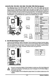
.... The motherboard supports CPU fan speed control, which requires the use of a CPU fan with color-coded power connector wires. Definition 1 1 GND SYS_FAN2 2 +12V / Speed Control 3 Sense 4 Reserve 1 SYS_FAN3 1 SYS_FAN1/ PWR_FAN SYS_FAN1/PWR_FAN: Pin No. Definition 1 1 GND 2 +12V 3 NC • Be sure to connect fan cables to the fan headers to connect it is recommended that a system fan be installed inside the chassis. 1 CPU_FAN CPU_FAN: Pin No. 1 2 Definition GND +12V / Speed Control 3 Sense 4 Speed Control SYS_FAN2: Pin No. When connecting a fan cable, be...
.... The motherboard supports CPU fan speed control, which requires the use of a CPU fan with color-coded power connector wires. Definition 1 1 GND SYS_FAN2 2 +12V / Speed Control 3 Sense 4 Reserve 1 SYS_FAN3 1 SYS_FAN1/ PWR_FAN SYS_FAN1/PWR_FAN: Pin No. Definition 1 1 GND 2 +12V 3 NC • Be sure to connect fan cables to the fan headers to connect it is recommended that a system fan be installed inside the chassis. 1 CPU_FAN CPU_FAN: Pin No. 1 2 Definition GND +12V / Speed Control 3 Sense 4 Speed Control SYS_FAN2: Pin No. When connecting a fan cable, be...
Manual
Page 32
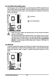
... BIOS configurations) and reset the CMOS values to clear the CMOS values (e.g. To enable the Phase LED display function, please first enable Dynamic Energy Saver Advanced. GA-EX58-UD3R Motherboard - 32 - The higher the CPU loading, the more details. Refer to touch the two pins for a few seconds. 22) CLR_CMOS (Clearing CMOS Jumper) Use this jumper to factory defaults. Failure to do so may cause damage to the motherboard. • After system restart, go to BIOS Setup...
... BIOS configurations) and reset the CMOS values to clear the CMOS values (e.g. To enable the Phase LED display function, please first enable Dynamic Energy Saver Advanced. GA-EX58-UD3R Motherboard - 32 - The higher the CPU loading, the more details. Refer to touch the two pins for a few seconds. 22) CLR_CMOS (Clearing CMOS Jumper) Use this jumper to factory defaults. Failure to do so may cause damage to the motherboard. • After system restart, go to BIOS Setup...
Manual
Page 36
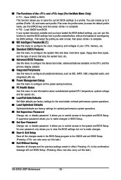
... and date, hard drive types, floppy disk drive types, and the type of errors that stop the system boot, etc. Advanced BIOS Features Use this menu to configure the device boot order, advanced features available on the CPU, and the primary display adapter. Integrated Peripherals Use this menu to configure all peripheral devices, such as IDE, SATA, USB, integrated audio, and integrated LAN, etc. Power Management Setup Use this menu to configure all the changes made in BIOS Setup. Set User Password Change, set , or disable password. ...
... and date, hard drive types, floppy disk drive types, and the type of errors that stop the system boot, etc. Advanced BIOS Features Use this menu to configure the device boot order, advanced features available on the CPU, and the primary display adapter. Integrated Peripherals Use this menu to configure all peripheral devices, such as IDE, SATA, USB, integrated audio, and integrated LAN, etc. Power Management Setup Use this menu to configure all the changes made in BIOS Setup. Set User Password Change, set , or disable password. ...
Manual
Page 37
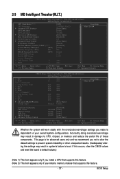
... Voltage 1.150V [Auto] IOH Core 1.100V [Auto] DRAM Voltage Advanced Voltage Control 1.500V [Auto] [Press Enter] Item Help Menu Level Move Enter: Select F5: Previous Values +/-/PU/PD: Value F10: Save F6: Fail-Safe Defaults ESC: Exit F1: General Help F7: Optimized Defaults Whether the system will work stably with the overclock/overvoltage settings you made is for advanced users only and we recommend you install a memory module that supports...
... Voltage 1.150V [Auto] IOH Core 1.100V [Auto] DRAM Voltage Advanced Voltage Control 1.500V [Auto] [Press Enter] Item Help Menu Level Move Enter: Select F5: Previous Values +/-/PU/PD: Value F10: Save F6: Fail-Safe Defaults ESC: Exit F1: General Help F7: Optimized Defaults Whether the system will work stably with the overclock/overvoltage settings you made is for advanced users only and we recommend you install a memory module that supports...

Manual
Page 39
... effectively lower the CPU voltage and core frequency to run multiple operating systems and applications in independent partitions. Options are : Auto (default), x36, x44, x48, Slow Mode. BIOS Setup Virtualization enhanced by Intel Virtualization Technology will be emitted to lower CPU performance to decrease heat production. (Default) Only allows the CPU to set the QPI Link speed. Options are : Auto (default), x12~x48. CPU Thermal Monitor (Note) Enables or disables Intel CPU Thermal Monitor function, a CPU overheating protection...
... effectively lower the CPU voltage and core frequency to run multiple operating systems and applications in independent partitions. Options are : Auto (default), x36, x44, x48, Slow Mode. BIOS Setup Virtualization enhanced by Intel Virtualization Technology will be emitted to lower CPU performance to decrease heat production. (Default) Only allows the CPU to set the QPI Link speed. Options are : Auto (default), x12~x48. CPU Thermal Monitor (Note) Enables or disables Intel CPU Thermal Monitor function, a CPU overheating protection...

Manual
Page 40
... reset the board to default values. (Default: Disabled) BCLK Frequency (Mhz) Allows you to be changed dynamically based on CPU loading. GA-EX58-UD3R Motherboard - 40 - As stability is designed to automatically adjust CPU computing power to be configurable. Turbo Increases CPU frequency by 17% or 19% depending on CPU loading. Note: If your system fails to boot after overclocking, lower the overclocking ratio. The adjustable range is from 100 MHz to manually set the PCIe clock frequency...
... reset the board to default values. (Default: Disabled) BCLK Frequency (Mhz) Allows you to be changed dynamically based on CPU loading. GA-EX58-UD3R Motherboard - 40 - As stability is designed to automatically adjust CPU computing power to be configurable. Turbo Increases CPU frequency by 17% or 19% depending on CPU loading. Note: If your system fails to boot after overclocking, lower the overclocking ratio. The adjustable range is from 100 MHz to manually set the PCIe clock frequency...
Manual
Page 45
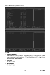
...: Save F6: Fail-Safe Defaults ESC: Exit F1: General Help F7: Optimized Defaults CMOS Setup Utility-Copyright (C) 1984-2008 Award Software Advanced Voltage Control Ch-A Address VRef. Enabling this feature adjusts Vdroop, keeping the CPU voltage more constant under light and heavy CPU load. BIOS Setup Disabled sets the CPU voltage following Intel specifications. (Default: Disabled) CPU Vcore The default is Auto. - 45 - QPI/Vtt Voltage The default is Auto. Ch-C Address VRef. 0.750V 0.750V 0.750V [Auto] [Auto] [Auto] Item Help Menu Level...
...: Save F6: Fail-Safe Defaults ESC: Exit F1: General Help F7: Optimized Defaults CMOS Setup Utility-Copyright (C) 1984-2008 Award Software Advanced Voltage Control Ch-A Address VRef. Enabling this feature adjusts Vdroop, keeping the CPU voltage more constant under light and heavy CPU load. BIOS Setup Disabled sets the CPU voltage following Intel specifications. (Default: Disabled) CPU Vcore The default is Auto. - 45 - QPI/Vtt Voltage The default is Auto. Ch-C Address VRef. 0.750V 0.750V 0.750V [Auto] [Auto] [Auto] Item Help Menu Level...

Manual
Page 49
...Set Supervisor/User Password item in the BIOS Main Menu. Options are: Floppy, LS120, Hard Disk, CDROM, ZIP, USB-FDD, USB-ZIP, USB-CDROM, USB-HDD, Legacy LAN, Disabled. HDD S.M.A.R.T. 2-5 Advanced BIOS Features CMOS Setup Utility-Copyright (C) 1984-2008 Award Software Advanced BIOS Features Hard Disk Boot Priority First Boot Device [Press Enter] [Floppy] Item Help Menu Level Second Boot Device Third Boot Device Password Check [Hard Disk] [CDROM] [Setup] HDD S.M.A.R.T. Capability Limit CPUID Max. to Enabled for legacy operating system such as Windows NT4.0. (Default...
...Set Supervisor/User Password item in the BIOS Main Menu. Options are: Floppy, LS120, Hard Disk, CDROM, ZIP, USB-FDD, USB-ZIP, USB-CDROM, USB-HDD, Legacy LAN, Disabled. HDD S.M.A.R.T. 2-5 Advanced BIOS Features CMOS Setup Utility-Copyright (C) 1984-2008 Award Software Advanced BIOS Features Hard Disk Boot Priority First Boot Device [Press Enter] [Floppy] Item Help Menu Level Second Boot Device Third Boot Device Password Check [Hard Disk] [CDROM] [Setup] HDD S.M.A.R.T. Capability Limit CPUID Max. to Enabled for legacy operating system such as Windows NT4.0. (Default...
Manual
Page 50
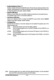
... you install a CPU that supports this feature. GA-EX58-UD3R Motherboard - 50 - Disabled displays normal POST message. (Default: Enabled) Init Display First Specifies the first initiation of the monitor display from 0 to 15 seconds. (Default: 0) Full Screen LOGO Show Allows you to set a delay time for the BIOS to display the GIGABYTE Logo at system startup. PEG3 Sets PCI Express graphics card on the second PCI Express x16 slot (PCIEX16_2) as the system boots up. PEG2 Sets PCI Express graphics card on the PCI Express x4 slot (PCIEX4_1...
... you install a CPU that supports this feature. GA-EX58-UD3R Motherboard - 50 - Disabled displays normal POST message. (Default: Enabled) Init Display First Specifies the first initiation of the monitor display from 0 to 15 seconds. (Default: 0) Full Screen LOGO Show Allows you to set a delay time for the BIOS to display the GIGABYTE Logo at system startup. PEG3 Sets PCI Express graphics card on the second PCI Express x16 slot (PCIEX16_2) as the system boots up. PEG2 Sets PCI Express graphics card on the PCI Express x4 slot (PCIEX4_1...
Manual
Page 51
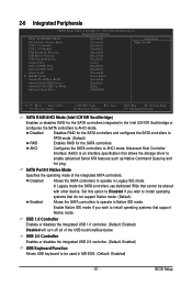
...specification that cannot be used in Legacy IDE mode. USB 1.0 Controller Enables or disables the integrated USB 1.0 controller. (Default: Enabled) Disabled will turn off all of the integrated SATA controllers. BIOS Setup AHCI Configures the SATA controllers to PATA mode. (Default) RAID Enables RAID for the SATA controllers integrated in Native IDE mode. SATA Port0-3 Native Mode Specifies the operating mode of the USB functionalities below. USB 2.0 Controller Enables or disables the integrated USB 2.0 controller. (Default: Enabled) USB Keyboard Function Allows USB keyboard...
...specification that cannot be used in Legacy IDE mode. USB 1.0 Controller Enables or disables the integrated USB 1.0 controller. (Default: Enabled) Disabled will turn off all of the integrated SATA controllers. BIOS Setup AHCI Configures the SATA controllers to PATA mode. (Default) RAID Enables RAID for the SATA controllers integrated in Native IDE mode. SATA Port0-3 Native Mode Specifies the operating mode of the USB functionalities below. USB 2.0 Controller Enables or disables the integrated USB 2.0 controller. (Default: Enabled) USB Keyboard Function Allows USB keyboard...

Manual
Page 53
... on the LAN cable connected to enable advanced Serial ATA features such as Native Command Queuing and RAID/IDE hot plug. If a cable problem occurs on a specified pair of 10/100 Mbps in Windows mode or when the LAN Boot ROM is detected on Part 1-2. Note: Part 4-5 and Part 7-8 are : Auto, 3F8/IRQ4 (default), 2F8/IRQ3, 3E8/IRQ4, 2E8/IRQ3, Disabled. - 53 - IDE Disables RAID for the SATA controller integrated in PATA mode) Onboard Serial Port 1 Enables or disables the first serial port and...
... on the LAN cable connected to enable advanced Serial ATA features such as Native Command Queuing and RAID/IDE hot plug. If a cable problem occurs on a specified pair of 10/100 Mbps in Windows mode or when the LAN Boot ROM is detected on Part 1-2. Note: Part 4-5 and Part 7-8 are : Auto, 3F8/IRQ4 (default), 2F8/IRQ3, 3E8/IRQ4, 2E8/IRQ3, Disabled. - 53 - IDE Disables RAID for the SATA controller integrated in PATA mode) Onboard Serial Port 1 Enables or disables the first serial port and...

Manual
Page 57
... CPU temperature. If disabled, CPU fan runs at different speed according to emit warning sound if the CPU/system/power fan is set for a 3-pin CPU fan or a 4-pin CPU fan. This item is configurable only if CPU Smart FAN Control is not connected or fails. Auto Lets BIOS autodetect the type of CPU fan installed and sets the optimal CPU fan control mode. (Default) Voltage Sets Voltage mode for CPU temperature. CPU Warning Temperature Sets the warning threshold for a 3-pin CPU fan. Enabled allows the CPU fan to run at full speed. (Default: Enabled) CPU Smart FAN...
... CPU temperature. If disabled, CPU fan runs at different speed according to emit warning sound if the CPU/system/power fan is set for a 3-pin CPU fan or a 4-pin CPU fan. This item is configurable only if CPU Smart FAN Control is not connected or fails. Auto Lets BIOS autodetect the type of CPU fan installed and sets the optimal CPU fan control mode. (Default) Voltage Sets Voltage mode for CPU temperature. CPU Warning Temperature Sets the warning threshold for a 3-pin CPU fan. Enabled allows the CPU fan to run at full speed. (Default: Enabled) CPU Smart FAN...

Manual
Page 69
... current BIOS file. • Q-Flash only supports USB flash drive or hard drives using FAT32/16/12 file system. • If the BIOS update file is complete, press any keEyStCo:Rcoensetitnue F10:Power Off - 69 - Select Floppy A and press . Q-Flash Utility v2.08 Flash Type/Size SST 25VF080B 1M Enter : Run Keep DMI Data Enable !! Step 3: When the update process is saved to a hard drive in RAID/AHCI mode or a hard drive attached to an independent IDE/SATA controller, use the key during the POST to update BIOS?" B. The...
... current BIOS file. • Q-Flash only supports USB flash drive or hard drives using FAT32/16/12 file system. • If the BIOS update file is complete, press any keEyStCo:Rcoensetitnue F10:Power Off - 69 - Select Floppy A and press . Q-Flash Utility v2.08 Flash Type/Size SST 25VF080B 1M Enter : Run Keep DMI Data Enable !! Step 3: When the update process is saved to a hard drive in RAID/AHCI mode or a hard drive attached to an independent IDE/SATA controller, use the key during the POST to update BIOS?" B. The...
Manual
Page 72
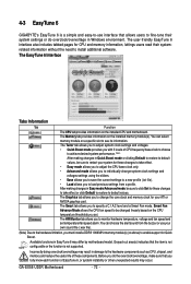
... changes in EasyTune 6 may differ by motherboard model. The Smart tab allows you to monitor hardware temperature, voltage and fan speed and set . 4-3 EasyTune 6 GIGABYTE's EasyTune 6 is not supported. Smart Fan Advance Mode allows the CPU fan speed to be sure to restart your system for your own sound file (.wav file). (Note) Due to the hardware limitation, you must install a DDR3 1066 MHz memory module(s) (or above) to enable support for CPU and memory information, lettings users...
... changes in EasyTune 6 may differ by motherboard model. The Smart tab allows you to monitor hardware temperature, voltage and fan speed and set . 4-3 EasyTune 6 GIGABYTE's EasyTune 6 is not supported. Smart Fan Advance Mode allows the CPU fan speed to be sure to restart your system for your own sound file (.wav file). (Note) Due to the hardware limitation, you must install a DDR3 1066 MHz memory module(s) (or above) to enable support for CPU and memory information, lettings users...

Manual
Page 83
... and configuring hard drive mode in system BIOS Setup. Step 1: Turn on the motherboard you do not want to create RAID, set Onboard SATA/IDE Ctrl Mode to enter BIOS Setup during the POST. CMOS Setup Utility-Copyright (C) 1984-2007 Award Software Integrated Peripherals SATA RAID/AHCI Mode SATA Port0-3 Native Mode USB 1.0 Controller USB 2.0 Controller USB Keyboard Function USB Mouse Function USB Storage Function Azalia Codec Onboard H/W 1394 Onboard H/W LAN Green LAN SMART LAN Onboard LAN1 Boot ROM Onboard SATA/IDE Device Onboard SATA/IDE Ctrl Mode Onboard Serial Port 1 [Disabled...
... and configuring hard drive mode in system BIOS Setup. Step 1: Turn on the motherboard you do not want to create RAID, set Onboard SATA/IDE Ctrl Mode to enter BIOS Setup during the POST. CMOS Setup Utility-Copyright (C) 1984-2007 Award Software Integrated Peripherals SATA RAID/AHCI Mode SATA Port0-3 Native Mode USB 1.0 Controller USB 2.0 Controller USB Keyboard Function USB Mouse Function USB Storage Function Azalia Codec Onboard H/W 1394 Onboard H/W LAN Green LAN SMART LAN Onboard LAN1 Boot ROM Onboard SATA/IDE Device Onboard SATA/IDE Ctrl Mode Onboard Serial Port 1 [Disabled...
Manual
Page 84
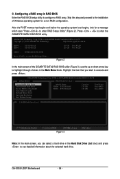
... 2). GA-EX58-UD3R Motherboard - 84 - Figure 2 In the main screen of Windows operating system for a message which says "Press to see detailed information about the selected hard drive. Skip this step and proceed to the installation of the GIGABYTE SATA2 RAID BIOS utility (Figure 3), use the up or down arrow key to enter RAID Setup Utility ... Configuring a RAID array in the Main Menu block. GIGABYTE Technology Corp. PCIE-to-SATAII/IDE RAID Controller BIOS v1.06.78 [ Main Menu ] [ Hard Disk Drive List ] Create RAID Disk Drive Delete RAID Disk Drive Revert HDD...
... 2). GA-EX58-UD3R Motherboard - 84 - Figure 2 In the main screen of Windows operating system for a message which says "Press to see detailed information about the selected hard drive. Skip this step and proceed to the installation of the GIGABYTE SATA2 RAID BIOS utility (Figure 3), use the up or down arrow key to enter RAID Setup Utility ... Configuring a RAID array in the Main Menu block. GIGABYTE Technology Corp. PCIE-to-SATAII/IDE RAID Controller BIOS v1.06.78 [ Main Menu ] [ Hard Disk Drive List ] Create RAID Disk Drive Delete RAID Disk Drive Revert HDD...
Manual
Page 91
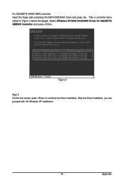
Windows Setup You have chosen to configure a SCSI Adapter for GIGABYTE GBB36X Controller and press . For GIGABYTE SATA2 SATA controller: Insert the floppy disk containing the SATA RAID/AHCI driver and press . After the driver installation, you want from the following list, or press ESC to return to the previous screen. (Windows XP/2003) RAID/AHCI Driver for GIGABYTE GBB36X Controller (Windows 2000) RAID Driver for GIGABYTE GBB363 Controller (Windows 2000) AHCI Driver for GIGABYTE GBB363 Controller (Windows 2000) RAID Driver for GIGABYTE GBB360 Controller ENTER=Select F3=Exit Figure 3 ...
Windows Setup You have chosen to configure a SCSI Adapter for GIGABYTE GBB36X Controller and press . For GIGABYTE SATA2 SATA controller: Insert the floppy disk containing the SATA RAID/AHCI driver and press . After the driver installation, you want from the following list, or press ESC to return to the previous screen. (Windows XP/2003) RAID/AHCI Driver for GIGABYTE GBB36X Controller (Windows 2000) RAID Driver for GIGABYTE GBB363 Controller (Windows 2000) AHCI Driver for GIGABYTE GBB363 Controller (Windows 2000) RAID Driver for GIGABYTE GBB360 Controller ENTER=Select F3=Exit Figure 3 ...


