
Manual
Page 4
...autorun screen and you use the Smart TPM utility, ensure that are recommended to install it. Installing the Infineon TPM Driver Insert the GIGABYTE motherboard driver disk. Click the Install All button and "Xpress Install" will automatically scan your system and list all of the drivers that ... the Infineon TPM driver. 2.2. 2. Click the Install button on the "Xpress Install" main menu to the Install New Utilities menu. Some motherboard driver disks include the Smart TPM utility in "Xpress Install." Installing the Infineon TPM Driver and the Smart TPM Utility Before you 'll be...
...autorun screen and you use the Smart TPM utility, ensure that are recommended to install it. Installing the Infineon TPM Driver Insert the GIGABYTE motherboard driver disk. Click the Install All button and "Xpress Install" will automatically scan your system and list all of the drivers that ... the Infineon TPM driver. 2.2. 2. Click the Install button on the "Xpress Install" main menu to the Install New Utilities menu. Some motherboard driver disks include the Smart TPM utility in "Xpress Install." Installing the Infineon TPM Driver and the Smart TPM Utility Before you 'll be...

Manual
Page 7
... on your phone. Then select the USB flash drive that you plug in the system BIOS. Before creating a Bluetooth cell phone key, make sure your motherboard includes a Bluetooth receiver and turn on the search and Bluetooth functions on the left will overwrite the former. 2. Create a Bluetooth cell phone key: Select the...
... on your phone. Then select the USB flash drive that you plug in the system BIOS. Before creating a Bluetooth cell phone key, make sure your motherboard includes a Bluetooth receiver and turn on the search and Bluetooth functions on the left will overwrite the former. 2. Create a Bluetooth cell phone key: Select the...

Manual
Page 19
...'t display your Bluetooth-enabled cell phone, click Refresh to let Smart TPM re-detect the device.) Before creating a Bluetooth cell phone key, make sure your motherboard includes a Bluetooth receiver and turn off or reset your PSD by plugging in BIOS Setup and then set earlier and click OK to "Enabled/Activate...
...'t display your Bluetooth-enabled cell phone, click Refresh to let Smart TPM re-detect the device.) Before creating a Bluetooth cell phone key, make sure your motherboard includes a Bluetooth receiver and turn off or reset your PSD by plugging in BIOS Setup and then set earlier and click OK to "Enabled/Activate...
Manual
Page 3
... Install" will automatically scan your system. Method 1: Insert the GIGABYTE motherboard driver disk. Install the GIGABYTE Ultra TPM utility. - 3 - "Xpress Install" will install all the drivers that the Infineon TPM driver and the GIGABYTE Ultra TPM utility have been installed in your system and list all... of the Infineon TPM Driver and GIGABYTE Ultra TPM items. Install the Infineon TPM driver. Method 2: To individually install...
... Install" will automatically scan your system. Method 1: Insert the GIGABYTE motherboard driver disk. Install the GIGABYTE Ultra TPM utility. - 3 - "Xpress Install" will install all the drivers that the Infineon TPM driver and the GIGABYTE Ultra TPM utility have been installed in your system and list all... of the Infineon TPM Driver and GIGABYTE Ultra TPM items. Install the Infineon TPM driver. Method 2: To individually install...
Manual
Page 1
GA-EP45-DS3R/ GA-EP45-DS3 LGA775 socket motherboard for Intel® CoreTM processor family/ Intel® Pentium® processor family/Intel® Celeron® processor family User's Manual Rev. 1004 12ME-EP45DS3R-1004R
GA-EP45-DS3R/ GA-EP45-DS3 LGA775 socket motherboard for Intel® CoreTM processor family/ Intel® Pentium® processor family/Intel® Celeron® processor family User's Manual Rev. 1004 12ME-EP45DS3R-1004R
Manual
Page 2
Motherboard GA-EP45-DS3R/GA-EP45-DS3 May 15, 2008 Motherboard GA-EP45-DS3R/ GA-EP45-DS3 May 15, 2008
Motherboard GA-EP45-DS3R/GA-EP45-DS3 May 15, 2008 Motherboard GA-EP45-DS3R/ GA-EP45-DS3 May 15, 2008
Manual
Page 3
... the exclu- For product-related information, check on our website at: http://www.gigabyte.com.tw Identifying Your Motherboard Revision The revision number on our website. No part of GIGABYTE. GIGABYTE UNITED INC. Disclaimer Information in this : "REV: X.X." Check your motherboard looks like this manual are legally registered to use of this manual may be...
... the exclu- For product-related information, check on our website at: http://www.gigabyte.com.tw Identifying Your Motherboard Revision The revision number on our website. No part of GIGABYTE. GIGABYTE UNITED INC. Disclaimer Information in this : "REV: X.X." Check your motherboard looks like this manual are legally registered to use of this manual may be...
Manual
Page 4
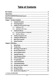
Table of Contents Box Contents ...6 OptionalItems ...6 GA-EP45-DS3R/DS3 Motherboard Layout 7 Block Diagram ...8 Chapter 1 Hardware Installation 9 1-1 Installation Precautions 9 1-2 Product Specifications 10 1-3 Installing the CPU and CPU Cooler 13 1-3-1 Installing the CPU 13 1-3-2 Installing the CPU ... 60 2-12 Set Supervisor/User Password 61 2-13 Save & Exit Setup 62 2-14 Exit Without Saving 62 2-15 Security Chip Configuration (Note 63 Only for GA-EP45-DS3R. - 4 -
Table of Contents Box Contents ...6 OptionalItems ...6 GA-EP45-DS3R/DS3 Motherboard Layout 7 Block Diagram ...8 Chapter 1 Hardware Installation 9 1-1 Installation Precautions 9 1-2 Product Specifications 10 1-3 Installing the CPU and CPU Cooler 13 1-3-1 Installing the CPU 13 1-3-2 Installing the CPU ... 60 2-12 Set Supervisor/User Password 61 2-13 Save & Exit Setup 62 2-14 Exit Without Saving 62 2-15 Security Chip Configuration (Note 63 Only for GA-EP45-DS3R. - 4 -

Manual
Page 6
... IDE cable and one floppy disk drive cable Four SATA 3Gb/s cables One SATA bracket I/O Shield Only for GA-EP45-DS3R. • The box contents above are subject to change without notice. • The motherboard image is for reference only and the actual items shall depend on product package you obtain. Optional Items 2-port...
... IDE cable and one floppy disk drive cable Four SATA 3Gb/s cables One SATA bracket I/O Shield Only for GA-EP45-DS3R. • The box contents above are subject to change without notice. • The motherboard image is for reference only and the actual items shall depend on product package you obtain. Optional Items 2-port...
Manual
Page 7
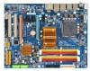
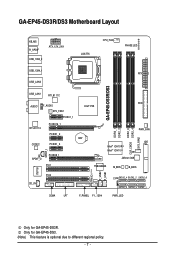
Only for GA-EP45-DS3R. GA-EP45-DS3R/DS3 Motherboard Layout KB_MS R_SPDIF ATX_12V_2X4 USB_1394_2 USB_1394_1 USB_LAN2 LGA775 CPU_FAN PHASE LED ATX GA-EP45-DS3R/DS3 USB_LAN1 RTL8111C FDD AUDIO F_AUDIO Intel® P45 SYS_FAN1 PCIEX1_1 RTL8111C PCIEX16_1 PCIEX1_2 CODEC PCIEX1_3 SPDIF_I SPDIF_O PCIEX8_1 PCI1 DDR2_1 DDR2_2 DDR2_3 ... B_BIOS TPM IC (Note) F_USB2 F_USB1 IT8718 PCI2 CD_IN CI SATA2_4 SATA2_2 SATA2_0 SATA2_5 SATA2_3 SATA2_1 COMA LPT F_PANEL F1_1394 PWR_LED Only for GA-EP45-DS3. (Note) This feature is optional due to different regional policy. - 7 -
Only for GA-EP45-DS3R. GA-EP45-DS3R/DS3 Motherboard Layout KB_MS R_SPDIF ATX_12V_2X4 USB_1394_2 USB_1394_1 USB_LAN2 LGA775 CPU_FAN PHASE LED ATX GA-EP45-DS3R/DS3 USB_LAN1 RTL8111C FDD AUDIO F_AUDIO Intel® P45 SYS_FAN1 PCIEX1_1 RTL8111C PCIEX16_1 PCIEX1_2 CODEC PCIEX1_3 SPDIF_I SPDIF_O PCIEX8_1 PCI1 DDR2_1 DDR2_2 DDR2_3 ... B_BIOS TPM IC (Note) F_USB2 F_USB1 IT8718 PCI2 CD_IN CI SATA2_4 SATA2_2 SATA2_0 SATA2_5 SATA2_3 SATA2_1 COMA LPT F_PANEL F1_1394 PWR_LED Only for GA-EP45-DS3. (Note) This feature is optional due to different regional policy. - 7 -

Manual
Page 9
...supply has been turned off. • Before turning on the power, make sure they are connected tightly and securely. • When handling the motherboard, avoid touching any installation steps or have it on top of an antistatic pad or within the computer casing. • Do not place the... computer system on an uneven surface. • Do not place the computer system in a high-temperature environment. • Turning on the motherboard, make sure the power supply voltage has been set according to the local voltage standard. • Before using the product, please verify that all ...
...supply has been turned off. • Before turning on the power, make sure they are connected tightly and securely. • When handling the motherboard, avoid touching any installation steps or have it on top of an antistatic pad or within the computer casing. • Do not place the... computer system on an uneven surface. • Do not place the computer system in a high-temperature environment. • Turning on the motherboard, make sure the power supply voltage has been set according to the local voltage standard. • Before using the product, please verify that all ...
Manual
Page 10
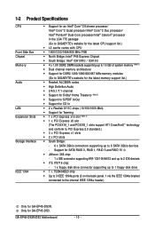
...system memory (Note 1) Š Dual channel memory architecture Š Support for DDR2 1200/1066/800/667 MHz memory modules (Go to GIGABYTE's website for the latest memory support list.) Š Realtek ALC889A codec Š High Definition Audio Š 2/4/5.1/7.1-channel Š Support ... PCI Express x1 slots Š 2 x PCI slots Š South Bridge: - 6 x SATA 3Gb/s connectors supporting up to 1 floppy disk drive Š T.I. GA-EP45-DS3R/DS3 Motherboard - 10 - TSB43AB23 chip Š Up to 3 IEEE 1394a ports (2 on the back panel, 1 via the IEEE 1394a bracket connected to 6 SATA 3Gb/s devices -...
...system memory (Note 1) Š Dual channel memory architecture Š Support for DDR2 1200/1066/800/667 MHz memory modules (Go to GIGABYTE's website for the latest memory support list.) Š Realtek ALC889A codec Š High Definition Audio Š 2/4/5.1/7.1-channel Š Support ... PCI Express x1 slots Š 2 x PCI slots Š South Bridge: - 6 x SATA 3Gb/s connectors supporting up to 1 floppy disk drive Š T.I. GA-EP45-DS3R/DS3 Motherboard - 10 - TSB43AB23 chip Š Up to 3 IEEE 1394a ports (2 on the back panel, 1 via the IEEE 1394a bracket connected to 6 SATA 3Gb/s devices -...
Manual
Page 12
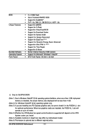
... actual memory size displayed will depend on the CPU/ System cooler you are installing one PCI Express graphics card, be sure to different regional policy. GA-EP45-DS3R/DS3 Motherboard - 12 - BIOS Unique Features Bundled Software Operating System Form Factor Š 2 x 8 Mbit flash Š Use of licensed AWARD BIOS ... Security (OEM version) Š Support for Microsoft® Windows® Vista/XP Š ATX Form Factor; 30.5cm x 24.4cm Only for GA-EP45-DS3R. (Note 1) Due to Windows Vista/XP 32-bit operating system limitation, when more than 4 GB. (Note 2) For Windows Vista/XP 32-bit ...
... actual memory size displayed will depend on the CPU/ System cooler you are installing one PCI Express graphics card, be sure to different regional policy. GA-EP45-DS3R/DS3 Motherboard - 12 - BIOS Unique Features Bundled Software Operating System Form Factor Š 2 x 8 Mbit flash Š Use of licensed AWARD BIOS ... Security (OEM version) Š Support for Microsoft® Windows® Vista/XP Š ATX Form Factor; 30.5cm x 24.4cm Only for GA-EP45-DS3R. (Note 1) Due to Windows Vista/XP 32-bit operating system limitation, when more than 4 GB. (Note 2) For Windows Vista/XP 32-bit ...

Manual
Page 13
... installing the CPU to prevent hardware damage. • Locate the pin one of the CPU. Hardware Installation mended that the motherboard supports the CPU. (Go to GIGABYTE's website for the peripherals. LGA775 CPU Socket Alignment Key LGA 775 CPU Alignment Key Pin One Corner of the CPU may ...to your hardware specifications including the CPU, graphics card, memory, hard drive, etc. 1-3-1 Installing the CPU A. Locate the alignment keys on the motherboard CPU socket and the notches on the CPU - 13 - It is not installed, otherwise overheating and damage of the CPU Socket Notch Notch ...
... installing the CPU to prevent hardware damage. • Locate the pin one of the CPU. Hardware Installation mended that the motherboard supports the CPU. (Go to GIGABYTE's website for the peripherals. LGA775 CPU Socket Alignment Key LGA 775 CPU Alignment Key Pin One Corner of the CPU may ...to your hardware specifications including the CPU, graphics card, memory, hard drive, etc. 1-3-1 Installing the CPU A. Locate the alignment keys on the motherboard CPU socket and the notches on the CPU - 13 - It is not installed, otherwise overheating and damage of the CPU Socket Notch Notch ...
Manual
Page 14
... CPU notches with your thumb and index fingers. Follow the steps below to the CPU. CPU Socket Lever Step 1: Completely raise the CPU socket lever. GA-EP45-DS3R/DS3 Motherboard - 14 - B. Step 5: Once the CPU is not installed.) Step 4: Hold the CPU with the socket alignment keys) and gently insert the CPU into its...
... CPU notches with your thumb and index fingers. Follow the steps below to the CPU. CPU Socket Lever Step 1: Completely raise the CPU socket lever. GA-EP45-DS3R/DS3 Motherboard - 14 - B. Step 5: Once the CPU is not installed.) Step 4: Hold the CPU with the socket alignment keys) and gently insert the CPU into its...
Manual
Page 15
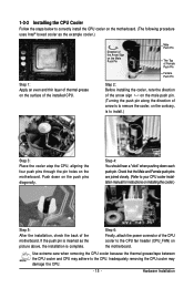
... the surface of arrow is to remove the cooler, on the contrary, is complete. Step 6: Finally, attach the power connector of the motherboard. Check that the Male and Female push pins are joined closely. (Refer to your CPU cooler installation manual for instructions on installing the cooler...the CPU cooler may adhere to the CPU. 1-3-2 Installing the CPU Cooler Follow the steps below to correctly install the CPU cooler on the motherboard. (The following procedure uses Intel® boxed cooler as the picture above, the installation is to install.) Step 3: Place the cooler atop...
... the surface of arrow is to remove the cooler, on the contrary, is complete. Step 6: Finally, attach the power connector of the motherboard. Check that the Male and Female push pins are joined closely. (Refer to your CPU cooler installation manual for instructions on installing the cooler...the CPU cooler may adhere to the CPU. 1-3-2 Installing the CPU Cooler Follow the steps below to correctly install the CPU cooler on the motherboard. (The following procedure uses Intel® boxed cooler as the picture above, the installation is to install.) Step 3: Place the cooler atop...
Manual
Page 16
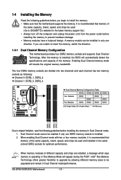
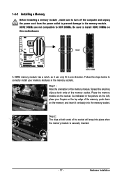
...appear during the POST. DS/SS - - - - When enabling Dual Channel mode with two or four memory modules, it is installed. 2. GA-EP45-DS3R/DS3 Motherboard - 16 - A memory module can be populated and remain in the same colored DDR2 sockets for the latest memory support list.) • ...a message which says memory is operating in only one DDR2 memory module is recommended that the motherboard supports the memory. Dual Channel mode cannot be used . (Go to GIGABYTE's website for optimum performance. 1-4 Installing the Memory Read the following guidelines before you are divided ...
...appear during the POST. DS/SS - - - - When enabling Dual Channel mode with two or four memory modules, it is installed. 2. GA-EP45-DS3R/DS3 Motherboard - 16 - A memory module can be populated and remain in the same colored DDR2 sockets for the latest memory support list.) • ...a message which says memory is operating in only one DDR2 memory module is recommended that the motherboard supports the memory. Dual Channel mode cannot be used . (Go to GIGABYTE's website for optimum performance. 1-4 Installing the Memory Read the following guidelines before you are divided ...
Manual
Page 17
... install your fingers on the top edge of the memory module. Follow the steps below to the memory module. Place the memory module on this motherboard. As indicated in the picture on the memory and insert it can only fit in the memory sockets. Step 1: Note the orientation of the memory...
... install your fingers on the top edge of the memory module. Follow the steps below to the memory module. Place the memory module on this motherboard. As indicated in the picture on the memory and insert it can only fit in the memory sockets. Step 1: Note the orientation of the memory...
Manual
Page 18
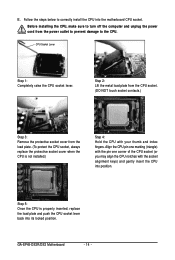
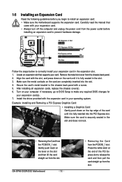
... turn off the computer and unplug the power cord from the power outlet before you begin to install an expansion card: • Make sure the motherboard supports the expansion card. Make sure the metal contacts on the card are completely inserted into the PCI Express slot. Secure the card's metal bracket... of the PCI Express slot to the chassis back panel with the slot, and press down on your expansion card(s). 7. Align the card with a screw. 5. GA-EP45-DS3R/DS3 Motherboard - 18 - • Removing the Card from the chassis back panel. 2.
... turn off the computer and unplug the power cord from the power outlet before you begin to install an expansion card: • Make sure the motherboard supports the expansion card. Make sure the metal contacts on the card are completely inserted into the PCI Express slot. Secure the card's metal bracket... of the PCI Express slot to the chassis back panel with the slot, and press down on your expansion card(s). 7. Align the card with a screw. 5. GA-EP45-DS3R/DS3 Motherboard - 18 - • Removing the Card from the chassis back panel. 2.
Manual
Page 19
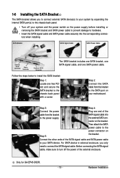
...below to install the SATA bracket: Step 1: Locate one SATA power cable. Before connecting the SATA signal cable, make sure to turn off your motherboard. Hardware Installation nector on your system and the power switch on Step 5: the bracket. For SATA device in external enclosure, you to connect ...SATA port on the bracket. Step 3: Step 4: Connect the power Plug one end of the external enclosure. the external SATA con- Only for GA-EP45-DS3R. - 19 - 1-6 Installing the SATA Bracket The SATA bracket allows you only need to connect the SATA signal cable.
...below to install the SATA bracket: Step 1: Locate one SATA power cable. Before connecting the SATA signal cable, make sure to turn off your motherboard. Hardware Installation nector on your system and the power switch on Step 5: the bracket. For SATA device in external enclosure, you to connect ...SATA port on the bracket. Step 3: Step 4: Connect the power Plug one end of the external enclosure. the external SATA con- Only for GA-EP45-DS3R. - 19 - 1-6 Installing the SATA Bracket The SATA bracket allows you only need to connect the SATA signal cable.


