
Manual
Page 1
Smart TPM User's Manual Rev. 1001 12MD-STPM-1001R • We recommend that you download the latest version of the Smart TPM utility from GIGABYTE's website. • If you have installed Ultra TPM earlier, you can install the Smart TPM utility directly without uninstalling Ultra TPM first. The original settings in Ultra TPM will be kept.
Smart TPM User's Manual Rev. 1001 12MD-STPM-1001R • We recommend that you download the latest version of the Smart TPM utility from GIGABYTE's website. • If you have installed Ultra TPM earlier, you can install the Smart TPM utility directly without uninstalling Ultra TPM first. The original settings in Ultra TPM will be kept.

Manual
Page 2
Installing the Infineon TPM Driver 4 2.2. Initializing the TPM Chip with the Smart TPM Utility 5 3.2. Other Bluetooth Settings 21 4.4. Installing the Infineon TPM Driver and the Smart TPM Utility 4 2.1. Configuring the System BIOS 3 2. Initializing the TPM chip 5 3.1. Advanced Mode...8 4. Other Features...21 - 2 - Configuring the Smart TPM Utility 18 4.1. Installing the Smart TPM Utility 4 3. Table of Contents TPM Configuration Procedure 3 1. Creating a Bluetooth Cell Phone Key 19 4.3. Creating a USB Key 18 4.2.
Installing the Infineon TPM Driver 4 2.2. Initializing the TPM Chip with the Smart TPM Utility 5 3.2. Other Bluetooth Settings 21 4.4. Installing the Infineon TPM Driver and the Smart TPM Utility 4 2.1. Configuring the System BIOS 3 2. Initializing the TPM chip 5 3.1. Advanced Mode...8 4. Other Features...21 - 2 - Configuring the Smart TPM Utility 18 4.1. Installing the Smart TPM Utility 4 3. Table of Contents TPM Configuration Procedure 3 1. Creating a Bluetooth Cell Phone Key 19 4.3. Creating a USB Key 18 4.2.

Manual
Page 3
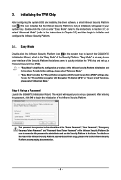
... the TPM chip, set the User Password in sequence: 1. TPM Configuration Procedure To enable the TPM, follow the steps below in the BIOS Setup program. - 3 - Installing the Infineon TPM driver and the Smart TPM utility 3. Configuring the System BIOS To use the Clear Security Chip setting (press + in the BIOS main...
... the TPM chip, set the User Password in sequence: 1. TPM Configuration Procedure To enable the TPM, follow the steps below in the BIOS Setup program. - 3 - Installing the Infineon TPM driver and the Smart TPM utility 3. Configuring the System BIOS To use the Clear Security Chip setting (press + in the BIOS main...

Manual
Page 4
... list all of the autorun screen and you use the Smart TPM utility, ensure that are recommended to the Install New Utilities menu. Installing the Infineon TPM Driver Insert the GIGABYTE motherboard driver disk. Installing the Smart TPM Utility Click the tab at the bottom of the left pane of the selected drivers, including...
... list all of the autorun screen and you use the Smart TPM utility, ensure that are recommended to the Install New Utilities menu. Installing the Infineon TPM Driver Insert the GIGABYTE motherboard driver disk. Installing the Smart TPM Utility Click the tab at the bottom of the left pane of the selected drivers, including...

Manual
Page 5
... initialized, will be able to access/close your Bluetooth cell phone or USB flash drive. Initializing the TPM chip After configuring the system BIOS and installing the driver software, the Infineon Security Platform icon , which your own password. You can select Advanced mode (refer to the instructions in Section 3.2) to launch...
... initialized, will be able to access/close your Bluetooth cell phone or USB flash drive. Initializing the TPM chip After configuring the system BIOS and installing the driver software, the Infineon Security Platform icon , which your own password. You can select Advanced mode (refer to the instructions in Section 3.2) to launch...

Manual
Page 14
... and the specified recipients will provide information how to prevent unauthorized persons from reading or changing your PSD. Using this wizard. The wizard will be installed only on Features Secure e-mail User-specific e-mail encryption and/or signing to configure secure e-mail. Only the user who created a file in Windows Vista...
... and the specified recipients will provide information how to prevent unauthorized persons from reading or changing your PSD. Using this wizard. The wizard will be installed only on Features Secure e-mail User-specific e-mail encryption and/or signing to configure secure e-mail. Only the user who created a file in Windows Vista...
Manual
Page 1
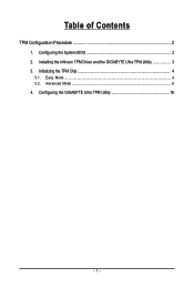
Table of Contents TPM Configuration Procedure 2 1. Configuring the GIGABYTE Ultra TPM Utility 16 - 1 - Easy Mode ...4 3.2. Advanced Mode ...6 4. Installing the Infineon TPM Driver and the GIGABYTE Ultra TPM Utility 3 3. Configuring the System BIOS 2 2. Initializing the TPM Chip 4 3.1.
Table of Contents TPM Configuration Procedure 2 1. Configuring the GIGABYTE Ultra TPM Utility 16 - 1 - Easy Mode ...4 3.2. Advanced Mode ...6 4. Installing the Infineon TPM Driver and the GIGABYTE Ultra TPM Utility 3 3. Configuring the System BIOS 2 2. Initializing the TPM Chip 4 3.1.
Manual
Page 2
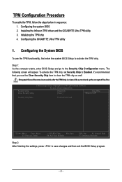
Configuring the GIGABYTE Ultra TPM utility 1. Be sure to save changes and then exit the BIOS Setup program. - 2 - Security Chip Clear Security Chip CMOS Setup Utility-Copyright (C) 1984-... Defaults ESC: Exit F1: General Help F7: Optimized Defaults Step 2: After finishing the settings, press to back up the encrypted files first. Installing the Infineon TPM driver and the GIGABYTE Ultra TPM utility 3. Encrypted files will appear. Configuring the System BIOS To use the Clear Security Chip item to activate the TPM...
Configuring the GIGABYTE Ultra TPM utility 1. Be sure to save changes and then exit the BIOS Setup program. - 2 - Security Chip Clear Security Chip CMOS Setup Utility-Copyright (C) 1984-... Defaults ESC: Exit F1: General Help F7: Optimized Defaults Step 2: After finishing the settings, press to back up the encrypted files first. Installing the Infineon TPM driver and the GIGABYTE Ultra TPM utility 3. Encrypted files will appear. Configuring the System BIOS To use the Clear Security Chip item to activate the TPM...
Manual
Page 3
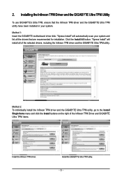
... TPM Driver and the GIGABYTE Ultra TPM Utility To use GIGABYTE's Ultra TPM, ensure that are recommended for installation. Method 1: Insert the GIGABYTE motherboard driver disk. "Xpress Install" will automatically scan your system. Click the Install All button. Install the GIGABYTE Ultra TPM utility. - 3 - Method 2: To individually install the Infineon TPM driver and the GIGABYTE Ultra TPM utility, go to...
... TPM Driver and the GIGABYTE Ultra TPM Utility To use GIGABYTE's Ultra TPM, ensure that are recommended for installation. Method 1: Insert the GIGABYTE motherboard driver disk. "Xpress Install" will automatically scan your system. Click the Install All button. Install the GIGABYTE Ultra TPM utility. - 3 - Method 2: To individually install the Infineon TPM driver and the GIGABYTE Ultra TPM utility, go to...
Manual
Page 4
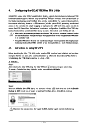
...Security Platform. Be sure to memorize this password to administrate and use the Security Platform in the system tray to launch the GIGABYTE Initialization Wizard, which is the "Easy Mode" of the Security Platform that the Infineon Security Platform is an easy-to ...- 4 - 3. Initializing the TPM Chip After configuring the system BIOS and installing the driver software, a small Infineon Security Platform icon (This icon indicates that allows users to set up a Password Launch the GIGABYTE Initialization Wizard. After entering the password, click OK to begin to the instructions ...
...Security Platform. Be sure to memorize this password to administrate and use the Security Platform in the system tray to launch the GIGABYTE Initialization Wizard, which is the "Easy Mode" of the Security Platform that the Infineon Security Platform is an easy-to ...- 4 - 3. Initializing the TPM Chip After configuring the system BIOS and installing the driver software, a small Infineon Security Platform icon (This icon indicates that allows users to set up a Password Launch the GIGABYTE Initialization Wizard. After entering the password, click OK to begin to the instructions ...

Manual
Page 12
... and files on the local computer. Using this feature guarantees that only the e-mail creator and the specified recipients will provide information how to be installed only on the local computer using the Microsoft Encrypting File System (EFS). Other users have to configure secure e-mail. If you chose to configure this...
... and files on the local computer. Using this feature guarantees that only the e-mail creator and the specified recipients will provide information how to be installed only on the local computer using the Microsoft Encrypting File System (EFS). Other users have to configure secure e-mail. If you chose to configure this...
Manual
Page 16
... function allows users to still have to access their keys in the system BIOS. The key(s) will appear in your system tray. Step 1: After installing the Ultra TPM utility, the Ultra TPM icon will be cracked or read. • Though the TPM delivers the latest data security technology, it ...store them up a PSD.) A. Initializing the TPM Chip to see how to continue. Refer to BIOS check box, or select at least set up . 4. GIGABYTE is not liable for Using Ultra TPM Before launching the Ultra TPM utility, make sure the TPM chip has been initialized and you have encrypted...
... function allows users to still have to access their keys in the system BIOS. The key(s) will appear in your system tray. Step 1: After installing the Ultra TPM utility, the Ultra TPM icon will be cracked or read. • Though the TPM delivers the latest data security technology, it ...store them up a PSD.) A. Initializing the TPM Chip to see how to continue. Refer to BIOS check box, or select at least set up . 4. GIGABYTE is not liable for Using Ultra TPM Before launching the Ultra TPM utility, make sure the TPM chip has been initialized and you have encrypted...
Manual
Page 3
... motherboard looks like this: "REV: X.X." sive global distributor of the motherboard is the property of the product, read the Quick Installation Guide included with the product. „ For detailed product information, carefully read the User's Manual. „ For instructions on ...how to the specifications and features in this manual may be made by GIGABYTE without GIGABYTE's prior written permission. by copyright laws and is 1.0. Disclaimer Information in this manual may be reproduced, copied, translated, transmitted...
... motherboard looks like this: "REV: X.X." sive global distributor of the motherboard is the property of the product, read the Quick Installation Guide included with the product. „ For detailed product information, carefully read the User's Manual. „ For instructions on ...how to the specifications and features in this manual may be made by GIGABYTE without GIGABYTE's prior written permission. by copyright laws and is 1.0. Disclaimer Information in this manual may be reproduced, copied, translated, transmitted...
Manual
Page 4
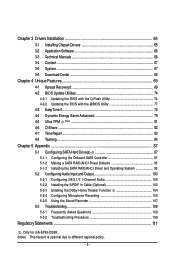
...Contents ...6 OptionalItems ...6 GA-EP45-DS3R/DS3 Motherboard Layout 7 Block Diagram ...8 Chapter 1 Hardware Installation 9 1-1 Installation Precautions 9 1-2 Product Specifications 10 1-3 Installing the CPU and CPU Cooler 13 1-3-1 Installing the CPU 13 1-3-2 Installing the CPU Cooler 15 1-4 Installing the Memory 16 1-4-1 Dual Channel Memory Configuration 16 1-4-2 Installing a Memory 17 1-5 Installing an Expansion Card 18 1-6 Installing the SATA Bracket 19 ...2-13 Save & Exit Setup 62 2-14 Exit Without Saving 62 2-15 Security Chip Configuration (Note 63 Only for GA-EP45-DS3R. - 4 -
...Contents ...6 OptionalItems ...6 GA-EP45-DS3R/DS3 Motherboard Layout 7 Block Diagram ...8 Chapter 1 Hardware Installation 9 1-1 Installation Precautions 9 1-2 Product Specifications 10 1-3 Installing the CPU and CPU Cooler 13 1-3-1 Installing the CPU 13 1-3-2 Installing the CPU Cooler 15 1-4 Installing the Memory 16 1-4-1 Dual Channel Memory Configuration 16 1-4-2 Installing a Memory 17 1-5 Installing an Expansion Card 18 1-6 Installing the SATA Bracket 19 ...2-13 Save & Exit Setup 62 2-14 Exit Without Saving 62 2-15 Security Chip Configuration (Note 63 Only for GA-EP45-DS3R. - 4 -
Manual
Page 5
... and Output 100 5-2-1 Configuring 2/4/5.1/7.1-Channel Audio 100 5-2-2 Installing the S/PDIF In Cable (Optional 102 5-2-3 Enabling the Dolby Home Theater Function 104 5-2-4 Configuring Microphone Recording 105 5-2-5 Using the Sound Recorder 107 5-3 Troubleshooting 108 5-3-1 Frequently Asked Questions 108 5-3-2 Troubleshooting Procedure 109 Regulatory Statements 111 Only for GA-EP45-DS3R. (Note) This feature is optional due to...
... and Output 100 5-2-1 Configuring 2/4/5.1/7.1-Channel Audio 100 5-2-2 Installing the S/PDIF In Cable (Optional 102 5-2-3 Enabling the Dolby Home Theater Function 104 5-2-4 Configuring Microphone Recording 105 5-2-5 Using the Sound Recorder 107 5-3 Troubleshooting 108 5-3-1 Frequently Asked Questions 108 5-3-2 Troubleshooting Procedure 109 Regulatory Statements 111 Only for GA-EP45-DS3R. (Note) This feature is optional due to...

Manual
Page 6
... cable (Part No. 12CF1-1LP001-01R) - 6 - The box contents are for reference only. Box Contents GA-EP45-DS3R or GA-EP45-DS3 motherboard Motherboard driver disk User's Manual Quick Installation Guide One IDE cable and one floppy disk drive cable Four SATA 3Gb/s cables One SATA bracket I/O Shield Only... for GA-EP45-DS3R. • The box contents above are subject to change without notice. • The motherboard image...
... cable (Part No. 12CF1-1LP001-01R) - 6 - The box contents are for reference only. Box Contents GA-EP45-DS3R or GA-EP45-DS3 motherboard Motherboard driver disk User's Manual Quick Installation Guide One IDE cable and one floppy disk drive cable Four SATA 3Gb/s cables One SATA bracket I/O Shield Only... for GA-EP45-DS3R. • The box contents above are subject to change without notice. • The motherboard image...

Manual
Page 9
... the AC power by your hardware components are connected tightly and securely. • When handling the motherboard, avoid touching any installation steps or have a problem related to the local voltage standard. • Before using the product, please verify that all cables... and power connectors of electrostatic discharge (ESD). Chapter 1 Hardware Installation 1-1 Installation Precautions The motherboard contains numerous delicate electronic circuits and components which can lead to damage to system components as well as ...
... the AC power by your hardware components are connected tightly and securely. • When handling the motherboard, avoid touching any installation steps or have a problem related to the local voltage standard. • Before using the product, please verify that all cables... and power connectors of electrostatic discharge (ESD). Chapter 1 Hardware Installation 1-1 Installation Precautions The motherboard contains numerous delicate electronic circuits and components which can lead to damage to system components as well as ...
Manual
Page 11
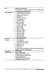
Hardware Installation USB Š Integrated in the South Bridge Š Up to 12 USB 2.0/1.1 ports (8 on the back panel, 4 via the USB brackets connected to the internal ...
Hardware Installation USB Š Integrated in the South Bridge Š Up to 12 USB 2.0/1.1 ports (8 on the back panel, 4 via the USB brackets connected to the internal ...
Manual
Page 12
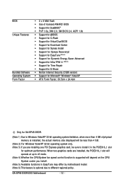
... may differ by motherboard model. (Note 6) This feature is installed, the actual memory size displayed will depend on the CPU/ System cooler you are installing one PCI Express graphics card, be sure to different regional policy. GA-EP45-DS3R/DS3 Motherboard - 12 - BIOS Unique Features Bundled Software Operating ... Factor; 30.5cm x 24.4cm Only for GA-EP45-DS3R. (Note 1) Due to Windows Vista/XP 32-bit operating system limitation, when more than 4 GB. (Note 2) For Windows Vista/XP 32-bit operating system only. (Note 3) If you install. (Note 5) Available functions in the PCIEX16_1 slot...
... may differ by motherboard model. (Note 6) This feature is installed, the actual memory size displayed will depend on the CPU/ System cooler you are installing one PCI Express graphics card, be sure to different regional policy. GA-EP45-DS3R/DS3 Motherboard - 12 - BIOS Unique Features Bundled Software Operating ... Factor; 30.5cm x 24.4cm Only for GA-EP45-DS3R. (Note 1) Due to Windows Vista/XP 32-bit operating system limitation, when more than 4 GB. (Note 2) For Windows Vista/XP 32-bit operating system only. (Note 3) If you install. (Note 5) Available functions in the PCIEX16_1 slot...

Manual
Page 13
... the standard specifications, please do so according to your hardware specifications including the CPU, graphics card, memory, hard drive, etc. 1-3-1 Installing the CPU A. LGA775 CPU Socket Alignment Key LGA 775 CPU Alignment Key Pin One Corner of the CPU Socket Notch Notch Triangle Pin One... before installing the CPU to prevent hardware damage. • Locate the pin one of the CPU. mended that the system bus frequency be inserted if oriented incorrectly. (Or you begin to install the CPU: • Make sure that the motherboard supports the CPU. (Go to GIGABYTE's website...
... the standard specifications, please do so according to your hardware specifications including the CPU, graphics card, memory, hard drive, etc. 1-3-1 Installing the CPU A. LGA775 CPU Socket Alignment Key LGA 775 CPU Alignment Key Pin One Corner of the CPU Socket Notch Notch Triangle Pin One... before installing the CPU to prevent hardware damage. • Locate the pin one of the CPU. mended that the system bus frequency be inserted if oriented incorrectly. (Or you begin to install the CPU: • Make sure that the motherboard supports the CPU. (Go to GIGABYTE's website...


