Manual
Page 4
Table of Contents Box Contents ...6 OptionalItems ...6 GA-E7AUM-DS2H Motherboard Layout 7 Block Diagram ...8 Chapter 1 Hardware Installation 9 1-1 Installation Precautions 9 1-2 Product Specifications 10 1-3 Installing the CPU and CPU Cooler 13 1-3-1 Installing the CPU 13 1-3-2 Installing the CPU Cooler 15 1-4 Installing the Memory 16 1-4-1 Dual Channel Memory Configuration 16 1-4-2 Installing a Memory 17 1-5 Installing an Expansion Card 18 1-6 Enabling the NVIDIA...
Table of Contents Box Contents ...6 OptionalItems ...6 GA-E7AUM-DS2H Motherboard Layout 7 Block Diagram ...8 Chapter 1 Hardware Installation 9 1-1 Installation Precautions 9 1-2 Product Specifications 10 1-3 Installing the CPU and CPU Cooler 13 1-3-1 Installing the CPU 13 1-3-2 Installing the CPU Cooler 15 1-4 Installing the Memory 16 1-4-1 Dual Channel Memory Configuration 16 1-4-2 Installing a Memory 17 1-5 Installing an Expansion Card 18 1-6 Enabling the NVIDIA...

Manual
Page 8
...) JMicron 368 1 PCI Express x1 ATA-133/100/66/33 IDE Channel PCI Bus TSB43AB23 2 IEEE 1394a Host Interface DDR2 800/667 MHz Dual Channel Memory NVIDIA® GeForce 9400 6 SATA 3Gb/s 12 USB Ports RTL 8211CL LAN RJ45 LPC BUS IT8718 CODEC Dual BIOS Floppy COM Port PS/2 KB or...
...) JMicron 368 1 PCI Express x1 ATA-133/100/66/33 IDE Channel PCI Bus TSB43AB23 2 IEEE 1394a Host Interface DDR2 800/667 MHz Dual Channel Memory NVIDIA® GeForce 9400 6 SATA 3Gb/s 12 USB Ports RTL 8211CL LAN RJ45 LPC BUS IT8718 CODEC Dual BIOS Floppy COM Port PS/2 KB or...

Manual
Page 9
... place the computer system in a high-temperature environment. • Turning on the computer power during the installation process can become damaged as a motherboard, CPU or memory. These stickers are required for warranty validation. • Always remove the AC power by your hardware components are connected. • To prevent damage to the...
... place the computer system in a high-temperature environment. • Turning on the computer power during the installation process can become damaged as a motherboard, CPU or memory. These stickers are required for warranty validation. • Always remove the AC power by your hardware components are connected. • To prevent damage to the...
Manual
Page 10
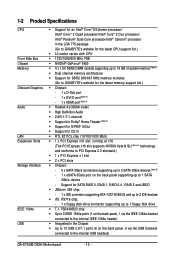
... bracket connected to the internal IEEE 1394a header) Integrated in the LGA 775 package (Go to GIGABYTE's website for the latest CPU support list.) L2 cache varies with CPU 1333/1066/800... 4 x 1.8V DDR2 DIMM sockets supporting up to 16 GB of system memory (Note 1) Dual channel memory architecture Support for DDR2 800/667 MHz memory modules (Go to GIGABYTE's website for the latest memory support list.) Chipset: - 1 x D-Sub port - 1 x DVI-D... back panel supporting up to the internal USB headers) GA-E7AUM-DS2H Motherboard - 10 -
... bracket connected to the internal IEEE 1394a header) Integrated in the LGA 775 package (Go to GIGABYTE's website for the latest CPU support list.) L2 cache varies with CPU 1333/1066/800... 4 x 1.8V DDR2 DIMM sockets supporting up to 16 GB of system memory (Note 1) Dual channel memory architecture Support for DDR2 800/667 MHz memory modules (Go to GIGABYTE's website for the latest memory support list.) Chipset: - 1 x D-Sub port - 1 x DVI-D... back panel supporting up to the internal USB headers) GA-E7AUM-DS2H Motherboard - 10 -
Manual
Page 12
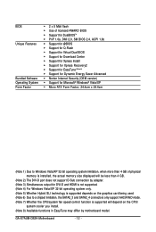
GA-E7AUM-DS2H Motherboard - 12 - BIOS Unique Features Bundled Software Operating System Form Factor 2 x 8 Mbit flash Use of licensed AWARD BIOS Support for DualBIOSTM ... Form Factor; 24.4cm x 24.4cm (Note 1) Due to Windows Vista/XP 32-bit operating system limitation, when more than 4 GB of physical memory is installed, the actual memory size displayed will be less than 4 GB. (Note 2) The DVI-D port does not support D-Sub connection by adapter. (Note 3) Simultaneous output for DVI...
GA-E7AUM-DS2H Motherboard - 12 - BIOS Unique Features Bundled Software Operating System Form Factor 2 x 8 Mbit flash Use of licensed AWARD BIOS Support for DualBIOSTM ... Form Factor; 24.4cm x 24.4cm (Note 1) Due to Windows Vista/XP 32-bit operating system limitation, when more than 4 GB of physical memory is installed, the actual memory size displayed will be less than 4 GB. (Note 2) The DVI-D port does not support D-Sub connection by adapter. (Note 3) Simultaneous output for DVI...

Manual
Page 13
... the power outlet before you wish to set beyond the standard specifications, please do so according to your hardware specifications including the CPU, graphics card, memory, hard drive, etc. 1-3-1 Installing the CPU A. The CPU cannot be set the frequency beyond hardware specifications since it does not meet the standard requirements for... before installing the CPU to prevent hardware damage. • Locate the pin one of the CPU. mended that the motherboard supports the CPU. (Go to GIGABYTE's website for the peripherals.
... the power outlet before you wish to set beyond the standard specifications, please do so according to your hardware specifications including the CPU, graphics card, memory, hard drive, etc. 1-3-1 Installing the CPU A. The CPU cannot be set the frequency beyond hardware specifications since it does not meet the standard requirements for... before installing the CPU to prevent hardware damage. • Locate the pin one of the CPU. mended that the motherboard supports the CPU. (Go to GIGABYTE's website for the peripherals.
Manual
Page 16
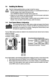
....) • Always turn off the computer and unplug the power cord from the power outlet before installing the memory to prevent hardware damage. • Memory modules have a foolproof design. DS/SS - - GA-E7AUM-DS2H Motherboard - 16 - A memory module can be used . (Go to GIGABYTE's website for optimum performance. When enabling Dual Channel mode with two or four...
....) • Always turn off the computer and unplug the power cord from the power outlet before installing the memory to prevent hardware damage. • Memory modules have a foolproof design. DS/SS - - GA-E7AUM-DS2H Motherboard - 16 - A memory module can be used . (Go to GIGABYTE's website for optimum performance. When enabling Dual Channel mode with two or four...

Manual
Page 17
... on this motherboard. Step 2: The clips at both ends of the socket will snap into the memory socket. Step 1: Note the orientation of the memory socket. 1-4-2 Installing a Memory Before installing a memory module , make sure to turn off the computer and unplug the power cord from the power outlet ...correctly install your fingers on the top edge of the memory, push down on the memory and insert it can only fit in the memory sockets. Notch DDR2 DIMM A DDR2 memory module has a notch, so it vertically into place when the memory module is securely inserted. - 17 - Follow the steps...
... on this motherboard. Step 2: The clips at both ends of the socket will snap into the memory socket. Step 1: Note the orientation of the memory socket. 1-4-2 Installing a Memory Before installing a memory module , make sure to turn off the computer and unplug the power cord from the power outlet ...correctly install your fingers on the top edge of the memory, push down on the memory and insert it can only fit in the memory sockets. Notch DDR2 DIMM A DDR2 memory module has a notch, so it vertically into place when the memory module is securely inserted. - 17 - Follow the steps...

Manual
Page 19
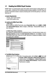
.... • Set iGPU Frame Buffer Control to Manual. • Set Frame Buffer Size to 256MB or 512MB. (Refer to see the current mode of system memory • Windows Vista operating system • Latest NVIDIA graphics driver • System BIOS that the Hybrid SLI-ready graphics card be installed after the system...
.... • Set iGPU Frame Buffer Control to Manual. • Set Frame Buffer Size to 256MB or 512MB. (Refer to see the current mode of system memory • Windows Vista operating system • Latest NVIDIA graphics driver • System BIOS that the Hybrid SLI-ready graphics card be installed after the system...
Manual
Page 20
... the GPU, PhysX will provide an exponential increase in physics processing power and will take gaming to access the utility. C. Restart your system when completed. GA-E7AUM-DS2H Motherboard - 20 - On the Settings tab, if GeForce PhysX has been selected under Advanced BIOS Features. (Refer to complete the installation. The NVIDIA PhysX Interface... in the operating system, click the Start icon . NVIDIA PhysX Utility Installation: After installing the operating system and motherboard drivers, on the right of system memory • Latest NVIDIA graphics driver B.
... the GPU, PhysX will provide an exponential increase in physics processing power and will take gaming to access the utility. C. Restart your system when completed. GA-E7AUM-DS2H Motherboard - 20 - On the Settings tab, if GeForce PhysX has been selected under Advanced BIOS Features. (Refer to complete the installation. The NVIDIA PhysX Interface... in the operating system, click the Start icon . NVIDIA PhysX Utility Installation: After installing the operating system and motherboard drivers, on the right of system memory • Latest NVIDIA graphics driver B.
Manual
Page 22
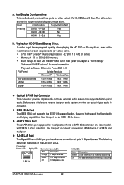
...1080p Blu-ray 1920 x 1080p 1920 x 1080p Optical S/PDIF Out Connector This connector provides digital audio out to SATA 3Gb/s standard and is occurring GA-E7AUM-DS2H Motherboard - 22 - Dual Combination Supported or Not Display DVI-D + D-Sub Yes DVI-D + HDMI No HDMI + D-Sub Yes B. eSATA 3Gb...the recommended system requirements (or better) below shows the supported dual display configurations. E1200 (1.6 GHz or faster) • Memory: 1 GB of DDR2 800 memory • BIOS Setup: At least 256 MB of the LAN port LEDs. Use this feature, ensure that supports digital ...
...1080p Blu-ray 1920 x 1080p 1920 x 1080p Optical S/PDIF Out Connector This connector provides digital audio out to SATA 3Gb/s standard and is occurring GA-E7AUM-DS2H Motherboard - 22 - Dual Combination Supported or Not Display DVI-D + D-Sub Yes DVI-D + HDMI No HDMI + D-Sub Yes B. eSATA 3Gb...the recommended system requirements (or better) below shows the supported dual display configurations. E1200 (1.6 GHz or faster) • Memory: 1 GB of DDR2 800 memory • BIOS Setup: At least 256 MB of the LAN port LEDs. Use this feature, ensure that supports digital ...

Manual
Page 38
... allows you to restrict access to the system and BIOS Setup. First enter the profile name (to erase the default profile name, use this task.) GA-E7AUM-DS2H Motherboard - 38 - You can use the SPACE key) and then press to complete. F12 : Load CMOS from a profile created before, without the hassles... program to the CMOS and exit BIOS Setup. (Pressing can also carry out this function to load the BIOS settings from BIOS If your CPU, memory, etc. Standard CMOS Features Use this menu to configure the system time and date, hard drive types, floppy disk drive types, and ...
... allows you to restrict access to the system and BIOS Setup. First enter the profile name (to erase the default profile name, use this task.) GA-E7AUM-DS2H Motherboard - 38 - You can use the SPACE key) and then press to complete. F12 : Load CMOS from a profile created before, without the hassles... program to the CMOS and exit BIOS Setup. (Pressing can also carry out this function to load the BIOS settings from BIOS If your CPU, memory, etc. Standard CMOS Features Use this menu to configure the system time and date, hard drive types, floppy disk drive types, and ...
Manual
Page 39
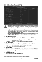
...MHz Actual MEM (DDR), Mhz Setting [Auto] Auto Auto 800.0 Auto 800.0 Current Value 800.0 800.0 Item Help Menu Level Memory Timing Setting Robust Graphics Booster x VGA Core Clock CPU Clock Ratio (Note) ******** System Voltage Optimized System Voltage Control x DDR2 Voltage Control x FSB ...manually; FSB (QDR), MHz Allows you set the System Voltage Control item to Auto to set the FSB-Memory ratio. (Default) Sync Mode Sets FSB-Memory ratio synchronously. BIOS Setup Incorrectly doing overclock/overvoltage may result in red, it is dependent on the FSB (...
...MHz Actual MEM (DDR), Mhz Setting [Auto] Auto Auto 800.0 Auto 800.0 Current Value 800.0 800.0 Item Help Menu Level Memory Timing Setting Robust Graphics Booster x VGA Core Clock CPU Clock Ratio (Note) ******** System Voltage Optimized System Voltage Control x DDR2 Voltage Control x FSB ...manually; FSB (QDR), MHz Allows you set the System Voltage Control item to Auto to set the FSB-Memory ratio. (Default) Sync Mode Sets FSB-Memory ratio synchronously. BIOS Setup Incorrectly doing overclock/overvoltage may result in red, it is dependent on the FSB (...

Manual
Page 40
... are : Optimal (default), Expert. Command Per Clock (CMD) Options are: Auto (default), 1 clock, 2 clock. ** Advanced Memory Settings ** tRRD Options are : Auto (default), 1~31. The adjustable range is set the memory frequency. tRAS Options are : Auto (default), 1~15. GA-E7AUM-DS2H Motherboard - 40 - Actual MEM (DDR), Mhz The value depends on the MEM (DDR), MHz setting...
... are : Optimal (default), Expert. Command Per Clock (CMD) Options are: Auto (default), 1 clock, 2 clock. ** Advanced Memory Settings ** tRRD Options are : Auto (default), 1~31. The adjustable range is set the memory frequency. tRAS Options are : Auto (default), 1~15. GA-E7AUM-DS2H Motherboard - 40 - Actual MEM (DDR), Mhz The value depends on the MEM (DDR), MHz setting...

Manual
Page 41
... allows all voltage control items below to be increased by 0.1V to 0.3V at 0.1V increment. Normal Supplies the memory voltage as required. (Default) +0.1V ~ +0.7V Increases memory voltage by 0.1V or 0.2V. FSB Voltage Control Allows you to set the system voltages as required. Normal Supplies the... for the graphics chip and is configurable only if the Robust Graphics Booster option is set to set the voltage of the graphics chip and memory. (Default: Disabled) VGA Core Clock Allows you install a CPU that supports this feature. - 41 - Normal CPU Vcore Displays the normal ...
... allows all voltage control items below to be increased by 0.1V to 0.3V at 0.1V increment. Normal Supplies the memory voltage as required. (Default) +0.1V ~ +0.7V Increases memory voltage by 0.1V or 0.2V. FSB Voltage Control Allows you to set the system voltages as required. Normal Supplies the... for the graphics chip and is configurable only if the Robust Graphics Booster option is set to set the voltage of the graphics chip and memory. (Default: Disabled) VGA Core Clock Allows you install a CPU that supports this feature. - 41 - Normal CPU Vcore Displays the normal ...
Manual
Page 42
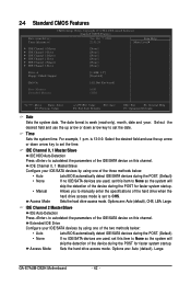
...format is 13:0:0. IDE Channel 0, 1 Master/Slave IDE HDD Auto-Detection Press to CHS. Sets the hard drive access mode. GA-E7AUM-DS2H Motherboard - 42 - Select the desired field and use the up arrow or down arrow key to set this item to manually...Channel 2 Slave [None] [None] [None] [None] [None] [None] Drive A Floppy 3 Mode Support [1.44M, 3.5"] [Disabled] Halt On [All, But Keyboard] Base Memory Extended Memory 640K 510M Move Enter: Select F5: Previous Values +/-/PU/PD: Value F10: Save F6: Fail-Safe Defaults ESC: Exit F1: General Help F7: Optimized Defaults...
...format is 13:0:0. IDE Channel 0, 1 Master/Slave IDE HDD Auto-Detection Press to CHS. Sets the hard drive access mode. GA-E7AUM-DS2H Motherboard - 42 - Select the desired field and use the up arrow or down arrow key to set this item to manually...Channel 2 Slave [None] [None] [None] [None] [None] [None] Drive A Floppy 3 Mode Support [1.44M, 3.5"] [Disabled] Halt On [All, But Keyboard] Base Memory Extended Memory 640K 510M Move Enter: Select F5: Previous Values +/-/PU/PD: Value F10: Save F6: Fail-Safe Defaults ESC: Exit F1: General Help F7: Optimized Defaults...

Manual
Page 43
...will not stop for a keyboard error but stop for all other errors. (Default) The system boot will not stop . Base Memory Also called conventional memory. The following fields display your system. If you to determine whether the system will be reserved for an error during the POST.... Head Precomp Landing Zone Sector Number of extended memory. - 43 - Floppy 3 Mode Support Allows you do not install a floppy disk drive, set this item to the information on the ...
...will not stop for a keyboard error but stop for all other errors. (Default) The system boot will not stop . Base Memory Also called conventional memory. The following fields display your system. If you to determine whether the system will be reserved for an error during the POST.... Head Precomp Landing Zone Sector Number of extended memory. - 43 - Floppy 3 Mode Support Allows you do not install a floppy disk drive, set this item to the information on the ...

Manual
Page 44
... the BIOS to automatically detect whether the current display is from the onboard VGA or a PCI Express graphics card and to 3 (Note) No-Execute Memory Protect (Note) CPU Enhanced Halt (C1E) (Note) C2/C2E State Support (Note) x C4/C4E State Support (Note) CPU Thermal Monitor 2(TM2...Hybrid SLI is enabled. to change the current display if it is different from the Init Diplay First setting. (Note) This item is installed. GA-E7AUM-DS2H Motherboard - 44 - Capability CPU Multi-Threading (Note) Limit CPUID Max. 2-5 Advanced BIOS Features CMOS Setup Utility-Copyright (C) 1984-2008 Award ...
... the BIOS to automatically detect whether the current display is from the onboard VGA or a PCI Express graphics card and to 3 (Note) No-Execute Memory Protect (Note) CPU Enhanced Halt (C1E) (Note) C2/C2E State Support (Note) x C4/C4E State Support (Note) CPU Thermal Monitor 2(TM2...Hybrid SLI is enabled. to change the current display if it is different from the Init Diplay First setting. (Note) This item is installed. GA-E7AUM-DS2H Motherboard - 44 - Capability CPU Multi-Threading (Note) Limit CPUID Max. 2-5 Advanced BIOS Features CMOS Setup Utility-Copyright (C) 1984-2008 Award ...

Manual
Page 45
...Always Enable. PEG Sets the PCI Express graphics card oas the first display. (Default) Hard Disk Boot Priority Specifies the sequence of system memory allocated solely for display. First/Second/Third Boot Device Specifies the boot order from the installed PCI graphics card, PCI Express graphics card or...Manual allows the Frame Buffer Size item below to Always Enable when Hybrid SLI is present only if you install a CPU that supports this memory for the onboard graphics controller. Use the up or down arrow key to select a device and press to manually set the password(s) ...
...Always Enable. PEG Sets the PCI Express graphics card oas the first display. (Default) Hard Disk Boot Priority Specifies the sequence of system memory allocated solely for display. First/Second/Third Boot Device Specifies the boot order from the installed PCI graphics card, PCI Express graphics card or...Manual allows the Frame Buffer Size item below to Always Enable when Hybrid SLI is present only if you install a CPU that supports this memory for the onboard graphics controller. Use the up or down arrow key to select a device and press to manually set the password(s) ...

Manual
Page 46
...Default: Enabled) C2/C2E State Support (Note) Allows you to determine whether to decrease average power consumption and heat production. (Default: Enabled) GA-E7AUM-DS2H Motherboard - 46 - HDD S.M.A.R.T. Set this item to let the CPU enter C4/C4E mode in system halt state. set this item to...voltage will be reduced during system halt state to Disabled for legacy operating system such as Windows NT4.0. (Default: Disabled) No-Execute Memory Protect (Note) Enables or disables Intel® Execute Disable Bit function. Depending on CPU loading, Intel® EIST technology can ...
...Default: Enabled) C2/C2E State Support (Note) Allows you to determine whether to decrease average power consumption and heat production. (Default: Enabled) GA-E7AUM-DS2H Motherboard - 46 - HDD S.M.A.R.T. Set this item to let the CPU enter C4/C4E mode in system halt state. set this item to...voltage will be reduced during system halt state to Disabled for legacy operating system such as Windows NT4.0. (Default: Disabled) No-Execute Memory Protect (Note) Enables or disables Intel® Execute Disable Bit function. Depending on CPU loading, Intel® EIST technology can ...


