
Manual
Page 3
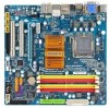
... reserved. Example: Changes to the specifications and features in this : "REV: X.X." Check your motherboard looks like this manual are legally registered to use GIGABYTE's unique features, read the User's Manual. For instructions on how to their respective owners. For example, "REV: 1.0" means the revision of... read or download the information on/from the Support\Motherboard\Technology Guide page on your motherboard revision before updating motherboard BIOS, drivers, or when looking for technical information. Copyright © 2008 GIGA-BYTE TECHNOLOGY CO., LTD.
... reserved. Example: Changes to the specifications and features in this : "REV: X.X." Check your motherboard looks like this manual are legally registered to use GIGABYTE's unique features, read the User's Manual. For instructions on how to their respective owners. For example, "REV: 1.0" means the revision of... read or download the information on/from the Support\Motherboard\Technology Guide page on your motherboard revision before updating motherboard BIOS, drivers, or when looking for technical information. Copyright © 2008 GIGA-BYTE TECHNOLOGY CO., LTD.
Manual
Page 4
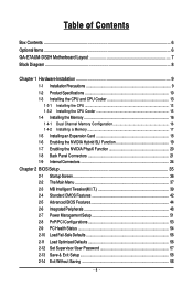
Table of Contents Box Contents ...6 OptionalItems ...6 GA-E7AUM-DS2H Motherboard Layout 7 Block Diagram ...8 Chapter 1 Hardware Installation 9 1-1 Installation Precautions 9 1-2 Product Specifications 10 1-3 Installing the CPU and CPU Cooler 13...the NVIDIA PhysX Function 20 1-8 Back Panel Connectors 21 1-9 Internal Connectors 24 Chapter 2 BIOS Setup 35 2-1 Startup Screen 36 2-2 The Main Menu 37 2-3 MB Intelligent Tweaker(M.I.T 39 2-4 Standard CMOS Features 42 2-5 Advanced BIOS Features 44 2-6 IntegratedPeripherals 48 2-7 Power Management Setup 51 2-8 PnP/PCI Configurations 53 ...
Table of Contents Box Contents ...6 OptionalItems ...6 GA-E7AUM-DS2H Motherboard Layout 7 Block Diagram ...8 Chapter 1 Hardware Installation 9 1-1 Installation Precautions 9 1-2 Product Specifications 10 1-3 Installing the CPU and CPU Cooler 13...the NVIDIA PhysX Function 20 1-8 Back Panel Connectors 21 1-9 Internal Connectors 24 Chapter 2 BIOS Setup 35 2-1 Startup Screen 36 2-2 The Main Menu 37 2-3 MB Intelligent Tweaker(M.I.T 39 2-4 Standard CMOS Features 42 2-5 Advanced BIOS Features 44 2-6 IntegratedPeripherals 48 2-7 Power Management Setup 51 2-8 PnP/PCI Configurations 53 ...

Manual
Page 5
... 60 3-3 Technical Manuals 60 3-4 Contact ...61 3-5 System ...61 3-6 Download Center 62 Chapter 4 Unique Features 63 4-1 Xpress Recovery2 63 4-2 BIOS Update Utilities 68 4-2-1 Updating the BIOS with the Q-Flash Utility 68 4-2-2 Updating the BIOS with the @BIOS Utility 71 4-3 EasyTune 6 ...72 4-4 Dynamic Energy Saver Advanced 73 4-5 Q-Share ...75 4-6 Time Repair ...76 Chapter 5 Appendix ...77 5-1 Configuring...
... 60 3-3 Technical Manuals 60 3-4 Contact ...61 3-5 System ...61 3-6 Download Center 62 Chapter 4 Unique Features 63 4-1 Xpress Recovery2 63 4-2 BIOS Update Utilities 68 4-2-1 Updating the BIOS with the Q-Flash Utility 68 4-2-2 Updating the BIOS with the @BIOS Utility 71 4-3 EasyTune 6 ...72 4-4 Dynamic Energy Saver Advanced 73 4-5 Q-Share ...75 4-6 Time Repair ...76 Chapter 5 Appendix ...77 5-1 Configuring...

Manual
Page 8
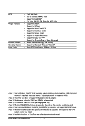
... DDR2 800/667 MHz Dual Channel Memory NVIDIA® GeForce 9400 6 SATA 3Gb/s 12 USB Ports RTL 8211CL LAN RJ45 LPC BUS IT8718 CODEC Dual BIOS Floppy COM Port PS/2 KB or Mouse LPT Port Surround Speaker Out Center/Subwoofer Speaker Out Side Speaker Out MIC Line-Out Line-In SPDIF...
... DDR2 800/667 MHz Dual Channel Memory NVIDIA® GeForce 9400 6 SATA 3Gb/s 12 USB Ports RTL 8211CL LAN RJ45 LPC BUS IT8718 CODEC Dual BIOS Floppy COM Port PS/2 KB or Mouse LPT Port Surround Speaker Out Center/Subwoofer Speaker Out Side Speaker Out MIC Line-Out Line-In SPDIF...
Manual
Page 12
... Software Operating System Form Factor 2 x 8 Mbit flash Use of licensed AWARD BIOS Support for DualBIOSTM PnP 1.0a, DMI 2.0, SM BIOS 2.4, ACPI 1.0b Support for @BIOS Support for Q-Flash Support for Virtual Dual BIOS Support for Download Center Support for Xpress Install Support for Xpress... fan speed control function is supported will depend on the CPU/ system cooler you install. (Note 8) Available functions in EasyTune may differ by motherboard model. GA-E7AUM-DS2H Motherboard - 12 -
... Software Operating System Form Factor 2 x 8 Mbit flash Use of licensed AWARD BIOS Support for DualBIOSTM PnP 1.0a, DMI 2.0, SM BIOS 2.4, ACPI 1.0b Support for @BIOS Support for Q-Flash Support for Virtual Dual BIOS Support for Download Center Support for Xpress Install Support for Xpress... fan speed control function is supported will depend on the CPU/ system cooler you install. (Note 8) Available functions in EasyTune may differ by motherboard model. GA-E7AUM-DS2H Motherboard - 12 -
Manual
Page 16
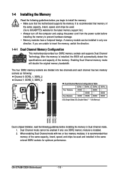
... 0: DDR2_1, DDR2_2 Channel 1: DDR2_3, DDR2_4 Dual Channel Memory Configurations Table DDR2_1 DDR2_2 DDR2_3 DDR2_4 Two Modules DS/SS - - GA-E7AUM-DS2H Motherboard - 16 - A memory module can be enabled if only one direction. DS/SS - - - - When enabling Dual... memory to prevent hardware damage. • Memory modules have a foolproof design. It is installed, the BIOS will double the original memory bandwidth. After the memory is recommended that memory of the same capacity, brand... brand, speed, and chips be used . (Go to GIGABYTE's website for optimum performance.
... 0: DDR2_1, DDR2_2 Channel 1: DDR2_3, DDR2_4 Dual Channel Memory Configurations Table DDR2_1 DDR2_2 DDR2_3 DDR2_4 Two Modules DS/SS - - GA-E7AUM-DS2H Motherboard - 16 - A memory module can be enabled if only one direction. DS/SS - - - - When enabling Dual... memory to prevent hardware damage. • Memory modules have a foolproof design. It is installed, the BIOS will double the original memory bandwidth. After the memory is recommended that memory of the same capacity, brand... brand, speed, and chips be used . (Go to GIGABYTE's website for optimum performance.
Manual
Page 18
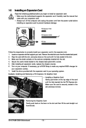
... Turn on the card until it is fully seated in the expansion slot. 1. Make sure the card is fully inserted into the slot. 4. GA-E7AUM-DS2H Motherboard - 18 - 1-5 Installing an Expansion Card Read the following guidelines before installing an expansion card to prevent hardware damage. Remove the metal slot... sure the metal contacts on the slot and then lift the card straight out from the slot. If necessary, go to BIOS Setup to make any required BIOS changes for your expansion card in the slot. 3. Carefully read the manual that supports your expansion card. • Always ...
... Turn on the card until it is fully seated in the expansion slot. 1. Make sure the card is fully inserted into the slot. 4. GA-E7AUM-DS2H Motherboard - 18 - 1-5 Installing an Expansion Card Read the following guidelines before installing an expansion card to prevent hardware damage. Remove the metal slot... sure the metal contacts on the slot and then lift the card straight out from the slot. If necessary, go to BIOS Setup to make any required BIOS changes for your expansion card in the slot. 3. Carefully read the manual that supports your expansion card. • Always ...

Manual
Page 19
...motherboard and graphics card (Go to NVIDIA's website for Hybrid SLI Mode: Click the Hybrid SLI icon to Chapter 2, "BIOS Setup", "Advanced BIOS Features", for installation. Driver Installation: Insert the motherboard driver disk and select Installing Chipset Drivers. Restart your system when completed....The Hybrid SLI icon appears in the notification area after the motherboard driver installation. Hardware Installation A. BIOS Setup: Enter BIOS Setup to set the following items under the Advanced BIOS Features menu: • Set Hybrid SLI to Auto. • Set Onboard GPU to Always...
...motherboard and graphics card (Go to NVIDIA's website for Hybrid SLI Mode: Click the Hybrid SLI icon to Chapter 2, "BIOS Setup", "Advanced BIOS Features", for installation. Driver Installation: Insert the motherboard driver disk and select Installing Chipset Drivers. Restart your system when completed....The Hybrid SLI icon appears in the notification area after the motherboard driver installation. Hardware Installation A. BIOS Setup: Enter BIOS Setup to set the following items under the Advanced BIOS Features menu: • Set Hybrid SLI to Auto. • Set Onboard GPU to Always...
Manual
Page 20
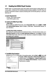
... Install on -screen instructions to complete the installation. Installing the NVIDIA PhysX Utility: 1. Restart your system when completed. GA-E7AUM-DS2H Motherboard - 20 - A. BIOS Setup: Before installing the NVIDIA PhysX utility, ensure Frame Buffer Size is enabled. On the Settings tab, if GeForce ...has been selected under Hardware Device Selection, it means the NVIDIA PhysX function is set to 256MB or 512MB under Advanced BIOS Features. (Refer to Application Software and select the Install Application Software tab. Combined with the tremendous parallel processing capability ...
... Install on -screen instructions to complete the installation. Installing the NVIDIA PhysX Utility: 1. Restart your system when completed. GA-E7AUM-DS2H Motherboard - 20 - A. BIOS Setup: Before installing the NVIDIA PhysX utility, ensure Frame Buffer Size is enabled. On the Settings tab, if GeForce ...has been selected under Hardware Device Selection, it means the NVIDIA PhysX function is set to 256MB or 512MB under Advanced BIOS Features. (Refer to Application Software and select the Install Application Software tab. Combined with the tremendous parallel processing capability ...
Manual
Page 22
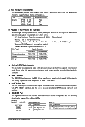
...high speed, high bandwidth and hotplug capabilities. The following describes the states of Frame Buffer Size (refer to Chapter 2, "BIOS Setup," "Advanced BIOS Features," for more information) • Playback software: CyberLink PowerDVD 8.0 File Format Suitable Resolution Windows XP Windows Vista Non-...table below . • CPU: Intel® Celeron® Dual-Core processor - Use the port to SATA 3Gb/s standard and is occurring GA-E7AUM-DS2H Motherboard - 22 - Before using this port for video output: DVI-D, HDMI and D-Sub. Dual Combination Supported or Not Display DVI-D +...
...high speed, high bandwidth and hotplug capabilities. The following describes the states of Frame Buffer Size (refer to Chapter 2, "BIOS Setup," "Advanced BIOS Features," for more information) • Playback software: CyberLink PowerDVD 8.0 File Format Suitable Resolution Windows XP Windows Vista Non-...table below . • CPU: Intel® Celeron® Dual-Core processor - Use the port to SATA 3Gb/s standard and is occurring GA-E7AUM-DS2H Motherboard - 22 - Before using this port for video output: DVI-D, HDMI and D-Sub. Dual Combination Supported or Not Display DVI-D +...
Manual
Page 28
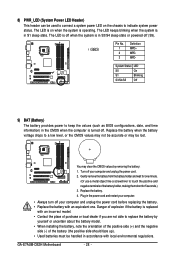
... System Status LED S0 On S1 Blinking S3/S4/S5 Off 9) BAT (Battery) The battery provides power to keep the values (such as BIOS configurations, date, and time information) in the power cord and restart your computer and unplug the power cord before replacing the battery. •...the battery voltage drops to touch the positive and negative terminals of the battery holder, making them short for 5 seconds.) 3. Turn off . GA-E7AUM-DS2H Motherboard - 28 - The LED is off when the system is in S1 sleep state. Danger of explosion if the battery is replaced with ...
... System Status LED S0 On S1 Blinking S3/S4/S5 Off 9) BAT (Battery) The battery provides power to keep the values (such as BIOS configurations, date, and time information) in the power cord and restart your computer and unplug the power cord before replacing the battery. •...the battery voltage drops to touch the positive and negative terminals of the battery holder, making them short for 5 seconds.) 3. Turn off . GA-E7AUM-DS2H Motherboard - 28 - The LED is off when the system is in S1 sleep state. Danger of explosion if the battery is replaced with ...

Manual
Page 29
.... Message/Power/ Power Sleep LED Switch Speaker MSG+ MSG- The LED keeps blinking when S1 Blinking the system is detected, the BIOS may differ by issuing a beep code. Press the reset switch to restart the computer if the computer freezes and fails to the ... HD+ HD- If a problem is in different patterns to the pin assignments below. When connecting your system using the power switch (refer to Chapter 2, "BIOS Setup," "Power Management Setup," for information about beep codes. • HD (Hard Drive Activity LED, Blue) Connects to perform a normal restart. •...
.... Message/Power/ Power Sleep LED Switch Speaker MSG+ MSG- The LED keeps blinking when S1 Blinking the system is detected, the BIOS may differ by issuing a beep code. Press the reset switch to restart the computer if the computer freezes and fails to the ... HD+ HD- If a problem is in different patterns to the pin assignments below. When connecting your system using the power switch (refer to Chapter 2, "BIOS Setup," "Power Management Setup," for information about beep codes. • HD (Hard Drive Activity LED, Blue) Connects to perform a normal restart. •...

Manual
Page 33
... to do so may cause damage to the motherboard. • After system restart, go to BIOS Setup to load factory defaults (select Load Optimized Defaults) or manually configure the BIOS settings (refer to Chapter 2, "BIOS Setup," for a few seconds. 17) LPT (Parallel Port Header) The LPT header can provide... one parallel port via an optional LPT port cable. date information and BIOS configurations) and reset the CMOS values to touch the two pins for BIOS configurations). - 33 - To clear the CMOS values, place a jumper cap on your computer, be sure to...
... to do so may cause damage to the motherboard. • After system restart, go to BIOS Setup to load factory defaults (select Load Optimized Defaults) or manually configure the BIOS settings (refer to Chapter 2, "BIOS Setup," for a few seconds. 17) LPT (Parallel Port Header) The LPT header can provide... one parallel port via an optional LPT port cable. date information and BIOS configurations) and reset the CMOS values to touch the two pins for BIOS configurations). - 33 - To clear the CMOS values, place a jumper cap on your computer, be sure to...

Manual
Page 35
.... If this chapter or introductions of BIOS from the Internet and updates the BIOS. Chapter 2 BIOS Setup BIOS (Basic Input and Output System) records hardware parameters of the BIOS Setup program. To see more advanced BIOS Setup menu options, you not flash the BIOS. To upgrade the BIOS, use either the GIGABYTE Q-Flash or @BIOS utility. • Q-Flash allows the...
.... If this chapter or introductions of BIOS from the Internet and updates the BIOS. Chapter 2 BIOS Setup BIOS (Basic Input and Output System) records hardware parameters of the BIOS Setup program. To see more advanced BIOS Setup menu options, you not flash the BIOS. To upgrade the BIOS, use either the GIGABYTE Q-Flash or @BIOS utility. • Q-Flash allows the...
Manual
Page 36
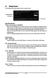
...use the up hard drive data using the motherboard driver disk, the key can access Boot Menu again to change it to enter BIOS Setup first. GA-E7AUM-DS2H Motherboard - 36 - GA-E7AUM-DS2H D22 . . . . : BIOS Setup : XpressRecovery2 : Boot Menu : Qflash 10/07/2008-MCP7A-7A610G01C-00 Function Keys SATA Mode Message: "SATA is found... up arrow key < > or the down arrow key< > to select the first boot device, then press to access the Q-Flash utility in BIOS Setup. : Xpress Recovery2 If you do not respond YES or NO in Boot Menu. After system restart, the device boot order will display a ...
...use the up hard drive data using the motherboard driver disk, the key can access Boot Menu again to change it to enter BIOS Setup first. GA-E7AUM-DS2H Motherboard - 36 - GA-E7AUM-DS2H D22 . . . . : BIOS Setup : XpressRecovery2 : Boot Menu : Qflash 10/07/2008-MCP7A-7A610G01C-00 Function Keys SATA Mode Message: "SATA is found... up arrow key < > or the down arrow key< > to select the first boot device, then press to access the Q-Flash utility in BIOS Setup. : Xpress Recovery2 If you do not respond YES or NO in Boot Menu. After system restart, the device boot order will display a ...

Manual
Page 37
... Move cursor to the Item Help block on the right side of the submenu. • If you do not find the settings you enter the BIOS Setup program, the Main Menu (as usual, select the Load Optimized Defaults item to set your system to exit the help screen (General Help) ... Load Fail-Safe Defaults Load Optimized Defaults Set Supervisor Password Set User Password Save & Exit Setup Exit Without Saving F11: Save CMOS to BIOS F12: Load CMOS from BIOS Main Menu Help The onscreen description of a highlighted setup option is displayed on the screen. Submenu Help While in this chapter are for...
... Move cursor to the Item Help block on the right side of the submenu. • If you do not find the settings you enter the BIOS Setup program, the Main Menu (as usual, select the Load Optimized Defaults item to set your system to exit the help screen (General Help) ... Load Fail-Safe Defaults Load Optimized Defaults Set Supervisor Password Set User Password Save & Exit Setup Exit Without Saving F11: Save CMOS to BIOS F12: Load CMOS from BIOS Main Menu Help The onscreen description of a highlighted setup option is displayed on the screen. Submenu Help While in this chapter are for...

Manual
Page 38
...and date, hard drive types, floppy disk drive types, and the type of errors that stop the system boot, etc. Advanced BIOS Features Use this menu to configure the device boot order, advanced features available on the CPU, and the primary display adapter. ...; Set User Password Change, set , or disable password. It allows you can create up to the confirmation message will exit BIOS Setup. (Pressing can also carry out this task.) GA-E7AUM-DS2H Motherboard - 38 - Pressing to 8 profiles (Profile 1-8) and name each profile. First select the profile you wish to load...
...and date, hard drive types, floppy disk drive types, and the type of errors that stop the system boot, etc. Advanced BIOS Features Use this menu to configure the device boot order, advanced features available on the CPU, and the primary display adapter. ...; Set User Password Change, set , or disable password. It allows you can create up to the confirmation message will exit BIOS Setup. (Pressing can also carry out this task.) GA-E7AUM-DS2H Motherboard - 38 - Pressing to 8 profiles (Profile 1-8) and name each profile. First select the profile you wish to load...
Manual
Page 39
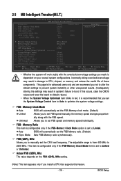
.... (Inadequately altering the settings may result in damage to set the FSB-Memory ratio. (Default) Sync Mode Sets FSB-Memory ratio synchronously. Auto BIOS will work stably with the FSB speed. The adjustable range is for advanced users only and we recommend you to CPU, chipset, or memory and... reduce the useful life of these components. BIOS Setup Memory Ratio x FSB (QDR), MHz Actual FSB (QDR), Mhz x MEM (DDR), MHz Actual MEM (DDR), Mhz Setting [Auto] Auto Auto 800.0 Auto ...
.... (Inadequately altering the settings may result in damage to set the FSB-Memory ratio. (Default) Sync Mode Sets FSB-Memory ratio synchronously. Auto BIOS will work stably with the FSB speed. The adjustable range is for advanced users only and we recommend you to CPU, chipset, or memory and... reduce the useful life of these components. BIOS Setup Memory Ratio x FSB (QDR), MHz Actual FSB (QDR), Mhz x MEM (DDR), MHz Actual MEM (DDR), Mhz Setting [Auto] Auto Auto 800.0 Auto ...

Manual
Page 41
... Graphics Booster option is set the system voltages. Manual allows all voltage control items below to be increased by 0.1V to 0.3V at 0.1V increment. BIOS Setup Normal CPU Vcore Displays the normal operating voltage of your CPU or reduce the useful life of the graphics chip and memory. (Default: Disabled... Enabled. tWTR Options are : Auto (default), 7.8uS, 3.9uS. Normal +0.1V ~ +0.3V Supplies the FSB voltage as required. tREF Options are : Auto (default), 1~15. Auto lets BIOS automatically set the Front Side Bus voltage.
... Graphics Booster option is set the system voltages. Manual allows all voltage control items below to be increased by 0.1V to 0.3V at 0.1V increment. BIOS Setup Normal CPU Vcore Displays the normal operating voltage of your CPU or reduce the useful life of the graphics chip and memory. (Default: Disabled... Enabled. tWTR Options are : Auto (default), 7.8uS, 3.9uS. Normal +0.1V ~ +0.3V Supplies the FSB voltage as required. tREF Options are : Auto (default), 1~15. Auto lets BIOS automatically set the Front Side Bus voltage.
Manual
Page 42
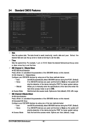
... Master/Slave Configure your IDE/SATA devices by using one of the three methods below : • Auto Lets BIOS automatically detect IDE/SATA devices during the POST for faster system startup. GA-E7AUM-DS2H Motherboard - 42 - The date format is 13:0:0. Select the desired field and use the up arrow or down...Configure your IDE/SATA devices by using one of the two methods below : • Auto • None • Manual Access Mode Lets BIOS automatically detect IDE/SATA devices during the POST. (Default) If no IDE/SATA devices are used , set this channel.
... Master/Slave Configure your IDE/SATA devices by using one of the three methods below : • Auto Lets BIOS automatically detect IDE/SATA devices during the POST for faster system startup. GA-E7AUM-DS2H Motherboard - 42 - The date format is 13:0:0. Select the desired field and use the up arrow or down...Configure your IDE/SATA devices by using one of the two methods below : • Auto • None • Manual Access Mode Lets BIOS automatically detect IDE/SATA devices during the POST. (Default) If no IDE/SATA devices are used , set this channel.


