Manual
Page 4
...the CPU Cooler 14 1-4 Installing the Memory 15 1-4-1 Dual Channel Memory Configuration 15 1-4-2 Installing a Memory 16 1-5 Installing an Expansion Card 17 1-6 Back Panel Connectors 18 1-7 Internal Connectors 20 Chapter 2 BIOS Setup 31 2-1 Startup Screen 32 2-2 The Main Menu 33 2-3 Standard CMOS Features 35 2-4 Advanced BIOS Features 37 2-5 IntegratedPeripherals 40 2-6 Power Management Setup 43 2-7 PnP/PCI Configurations 45 2-8 PC Health Status 46 2-9 Frequency/Voltage Control 48 2-10 Load Fail-Safe Defaults 50 2-11 Load Optimized Defaults 50 2-12 Set Supervisor/User Password...
...the CPU Cooler 14 1-4 Installing the Memory 15 1-4-1 Dual Channel Memory Configuration 15 1-4-2 Installing a Memory 16 1-5 Installing an Expansion Card 17 1-6 Back Panel Connectors 18 1-7 Internal Connectors 20 Chapter 2 BIOS Setup 31 2-1 Startup Screen 32 2-2 The Main Menu 33 2-3 Standard CMOS Features 35 2-4 Advanced BIOS Features 37 2-5 IntegratedPeripherals 40 2-6 Power Management Setup 43 2-7 PnP/PCI Configurations 45 2-8 PC Health Status 46 2-9 Frequency/Voltage Control 48 2-10 Load Fail-Safe Defaults 50 2-11 Load Optimized Defaults 50 2-12 Set Supervisor/User Password...
Manual
Page 10
...the back panel, 4 via the USB brackets connected to the internal USB headers) Internal Connectors Š 1 x 24-pin ATX main power connector Š 1 x 4-pin ATX 12V power connector Š 1 x floppy disk drive connector Š 1 x IDE connector Š 4 x SATA 3Gb/s connectors Š 1 x CPU fan header Š 1 x system fan header Š 1 x front panel header Š 1 x front panel audio header Š 1 x CD In connector Š 1 x S/PDIF In/Out header Š 2 x USB 2.0/1.1 headers Š 1 x chassis intrusion header Š 1 x power LED header GA-946GMX-S2 Motherboard - 10...
...the back panel, 4 via the USB brackets connected to the internal USB headers) Internal Connectors Š 1 x 24-pin ATX main power connector Š 1 x 4-pin ATX 12V power connector Š 1 x floppy disk drive connector Š 1 x IDE connector Š 4 x SATA 3Gb/s connectors Š 1 x CPU fan header Š 1 x system fan header Š 1 x front panel header Š 1 x front panel audio header Š 1 x CD In connector Š 1 x S/PDIF In/Out header Š 2 x USB 2.0/1.1 headers Š 1 x chassis intrusion header Š 1 x power LED header GA-946GMX-S2 Motherboard - 10...
Manual
Page 15
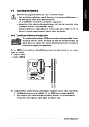
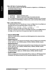
...used . (Go to GIGABYTE's website for the latest memory support list.) • Always turn off the computer and unplug the power cord from the power outlet before installing the memory to insert the memory, switch the direction. 1-4-1 Dual Channel Memory Configuration This motherboard provides two DDR2 memory sockets and supports Dual Channel Technology. Hardware Installation Enabling Dual Channel memory mode will automatically detect the specifications and capacity of the memory. When enabling Dual Channel mode with two memory modules, it is recommended that the motherboard supports...
...used . (Go to GIGABYTE's website for the latest memory support list.) • Always turn off the computer and unplug the power cord from the power outlet before installing the memory to insert the memory, switch the direction. 1-4-1 Dual Channel Memory Configuration This motherboard provides two DDR2 memory sockets and supports Dual Channel Technology. Hardware Installation Enabling Dual Channel memory mode will automatically detect the specifications and capacity of the memory. When enabling Dual Channel mode with two memory modules, it is recommended that the motherboard supports...
Manual
Page 17
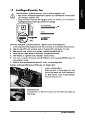
... BIOS changes for your expansion card(s). 7. After installing all expansion cards, replace the chassis cover(s). 6. Example: Installing and Removing a PCI Express x16 Graphics Card: • Installing a Graphics Card: Gently push down on your card. Hardware Installation Turn on the card until it is fully seated in the expansion slot. 1. If necessary, go to BIOS Setup to install an expansion card: • Make sure the motherboard supports the expansion card. PCI Express x16 Slot PCI Slot PCI Express x4 Slot Follow the steps below to the chassis back panel...
... BIOS changes for your expansion card(s). 7. After installing all expansion cards, replace the chassis cover(s). 6. Example: Installing and Removing a PCI Express x16 Graphics Card: • Installing a Graphics Card: Gently push down on your card. Hardware Installation Turn on the card until it is fully seated in the expansion slot. 1. If necessary, go to BIOS Setup to install an expansion card: • Make sure the motherboard supports the expansion card. PCI Express x16 Slot PCI Slot PCI Express x4 Slot Follow the steps below to the chassis back panel...
Manual
Page 22
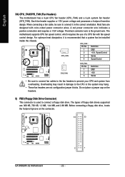
... motherboard has a 4-pin CPU fan header (CPU_FAN) and a 3-pin system fan header (SYS_FAN). When connecting a fan cable, be installed inside the chassis. A red power connector wire indicates a positive connection and requires a +12V voltage. CPU_FAN : Pin No. Overheating may hang. • These fan headers are designed with fan speed control design. The types of a CPU fan with color-coded power connector wires. Before connecting a floppy disk drive, locate the foolproof groove on the headers. 5) FDD (Floppy Disk Drive Connector) This connector is used to connect a floppy disk...
... motherboard has a 4-pin CPU fan header (CPU_FAN) and a 3-pin system fan header (SYS_FAN). When connecting a fan cable, be installed inside the chassis. A red power connector wire indicates a positive connection and requires a +12V voltage. CPU_FAN : Pin No. Overheating may hang. • These fan headers are designed with fan speed control design. The types of a CPU fan with color-coded power connector wires. Before connecting a floppy disk drive, locate the foolproof groove on the headers. 5) FDD (Floppy Disk Drive Connector) This connector is used to connect a floppy disk...
Manual
Page 24
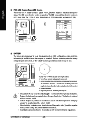
... the battery model. • When installing the battery, note the orientation of the positive side (+) and the negative side (-) of purchase or local dealer if you are not able to a low level, or the CMOS values may not be accurate or may clear the CMOS values by removing the battery: 1. Replace the battery. 4. English 8) PWR_LED (System Power LED Header) This header can be used to connect a system power LED...
... the battery model. • When installing the battery, note the orientation of the positive side (+) and the negative side (-) of purchase or local dealer if you are not able to a low level, or the CMOS values may not be accurate or may clear the CMOS values by removing the battery: 1. Replace the battery. 4. English 8) PWR_LED (System Power LED Header) This header can be used to connect a system power LED...
Manual
Page 26
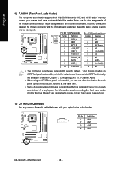
...-R GA-946GMX-S2 Motherboard - 26 - English 11) F_AUDIO (Front Panel Audio Header) The front panel audio header supports Intel High Definition audio (HD) and AC'97 audio. If your chassis provides an AC'97 front panel audio module, refer to the instructions on how to activate AC'97 functioninality via the audio software in Chapter 5, "Configuring 2/4/5.1/7.1-Channel Audio." • When using an AC'97 front panel audio module, you can use either the front or the back panel audio connectors...
...-R GA-946GMX-S2 Motherboard - 26 - English 11) F_AUDIO (Front Panel Audio Header) The front panel audio header supports Intel High Definition audio (HD) and AC'97 audio. If your chassis provides an AC'97 front panel audio module, refer to the instructions on how to activate AC'97 functioninality via the audio software in Chapter 5, "Configuring 2/4/5.1/7.1-Channel Audio." • When using an AC'97 front panel audio module, you can use either the front or the back panel audio connectors...
Manual
Page 28
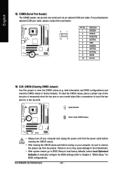
... BNo Pin 16) CLR_CMOS (Clearing CMOS Jumper) Use this jumper to Chapter 2, "BIOS Setup," for a few seconds. Failure to do so may cause damage to the motherboard. • After system restart, go to BIOS Setup to load factory defaults (select Load Optimized Defaults) or manually configure the BIOS settings (refer to clear the CMOS values (e.g. date information and BIOS configurations) and reset the CMOS values to remove the jumper cap from the jumper. GA-946GMX-S2 Motherboard - 28 - English 15) COMB (Serial Port Header) The COMB header...
... BNo Pin 16) CLR_CMOS (Clearing CMOS Jumper) Use this jumper to Chapter 2, "BIOS Setup," for a few seconds. Failure to do so may cause damage to the motherboard. • After system restart, go to BIOS Setup to load factory defaults (select Load Optimized Defaults) or manually configure the BIOS settings (refer to clear the CMOS values (e.g. date information and BIOS configurations) and reset the CMOS values to remove the jumper cap from the jumper. GA-946GMX-S2 Motherboard - 28 - English 15) COMB (Serial Port Header) The COMB header...
Manual
Page 34
... BIOS If your CPU, memory, etc. „ Load Fail-Safe Defaults Fail-Safe defaults are factory settings for the most stable, minimal-performance system operations. „ Load Optimized Defaults Optimized defaults are factory settings for optimal-performance system operations. „ Set Supervisor Password Change, set , or disable password. First enter the profile name (to erase the default profile name, use this task.) GA-946GMX-S2 Motherboard - 34 - An user password only allows you to make changes. „ Save & Exit Setup...
... BIOS If your CPU, memory, etc. „ Load Fail-Safe Defaults Fail-Safe defaults are factory settings for the most stable, minimal-performance system operations. „ Load Optimized Defaults Optimized defaults are factory settings for optimal-performance system operations. „ Set Supervisor Password Change, set , or disable password. First enter the profile name (to erase the default profile name, use this task.) GA-946GMX-S2 Motherboard - 34 - An user password only allows you to make changes. „ Save & Exit Setup...

Manual
Page 37
... visit Intel's website. - 37 - Press to accept. Setup A password is only required for entering the BIOS Setup program. (Default) System A password is required for booting the system and for entering the BIOS Setup program. Options are: Floppy, LS120, Hard Disk, CDROM, ZIP, USB-FDD, USB-ZIP, USB-CDROM, USB-HDD, LAN, Disabled. Use the up or down arrow key to select a device and press to exit this item, set the password(s) under the Set Supervisor/User Password item in the BIOS Main Menu.
... visit Intel's website. - 37 - Press to accept. Setup A password is only required for entering the BIOS Setup program. (Default) System A password is required for booting the system and for entering the BIOS Setup program. Options are: Floppy, LS120, Hard Disk, CDROM, ZIP, USB-FDD, USB-ZIP, USB-CDROM, USB-HDD, LAN, Disabled. Use the up or down arrow key to select a device and press to exit this item, set the password(s) under the Set Supervisor/User Password item in the BIOS Main Menu.
Manual
Page 38
...for legacy operating system such as the first display. Depending on CPU loading, Intel® EIST technology can function as the first display. PCI Sets the PCI graphics card as the first display. (Default) Onboard VGA Sets the onboard VGA as Windows NT4.0. (Default: Disabled) No-Execute Memory Protect (Note) Enables or disables Intel® Execute Disable Bit function. GA-946GMX-S2 Motherboard - 38 - This feature only works for the computer, reducing exposure to decrease average power consumption and heat production. (Default: Enabled) Virtualization Technology (Note...
...for legacy operating system such as the first display. Depending on CPU loading, Intel® EIST technology can function as the first display. PCI Sets the PCI graphics card as the first display. (Default) Onboard VGA Sets the onboard VGA as Windows NT4.0. (Default: Disabled) No-Execute Memory Protect (Note) Enables or disables Intel® Execute Disable Bit function. GA-946GMX-S2 Motherboard - 38 - This feature only works for the computer, reducing exposure to decrease average power consumption and heat production. (Default: Enabled) Virtualization Technology (Note...

Manual
Page 39
... PCI Express VGA card is installed. (Default) Always Enable Always activates the onboard VGA, whether or not a PCI Express card is the total amount of system memory allocated solely for display. English Onboard VGA Enables or disables the onboard VGA function. On-Chip Frame Buffer Size Frame buffer size is installed. Options are: 8M (default), 1M. - 39 - BIOS Setup MS-DOS, for example, will use only this item to Always Enable. If you wish to set up a dual view configuration, set this memory for the onboard graphics controller...
... PCI Express VGA card is installed. (Default) Always Enable Always activates the onboard VGA, whether or not a PCI Express card is the total amount of system memory allocated solely for display. English Onboard VGA Enables or disables the onboard VGA function. On-Chip Frame Buffer Size Frame buffer size is installed. Options are: 8M (default), 1M. - 39 - BIOS Setup MS-DOS, for example, will use only this item to Always Enable. If you wish to set up a dual view configuration, set this memory for the onboard graphics controller...

Manual
Page 40
...-Chip SATA Mode and PATA IDE Set to Combined. Disabled Disables the integrated SATA controller. Auto Lets BIOS set to settings. SATA Port 0/2 Set to This value is set SATA devices to operate in SATA mode. Ch.0 Master/Slave Sets the IDE channels to Ch. 0 Master/Slave. (Default) Ch.1 Master/Slave Sets the IDE channels to USB Controller USB 2.0 Controller USB Keyboard Support USB Mouse Support Legacy USB storage detect Azalia Codec Onboard H/W LAN ` SMART LAN Onboard LAN Boot ROM Onboard Serial Port 1 Onboard Serial Port 2 Onboard Parallel Port Parallel Port Mode [Enabled] [Auto...
...-Chip SATA Mode and PATA IDE Set to Combined. Disabled Disables the integrated SATA controller. Auto Lets BIOS set to settings. SATA Port 0/2 Set to This value is set SATA devices to operate in SATA mode. Ch.0 Master/Slave Sets the IDE channels to Ch. 0 Master/Slave. (Default) Ch.1 Master/Slave Sets the IDE channels to USB Controller USB 2.0 Controller USB Keyboard Support USB Mouse Support Legacy USB storage detect Azalia Codec Onboard H/W LAN ` SMART LAN Onboard LAN Boot ROM Onboard Serial Port 1 Onboard Serial Port 2 Onboard Parallel Port Parallel Port Mode [Enabled] [Auto...

Manual
Page 41
... in network card instead of wires will turn off all four pairs of using the onboard audio, set this item to the fault or short. BIOS Setup USB 2.0 Controller Enables or disables the integrated USB 2.0 controller. (Default: Enabled) USB Keyboard Support Allows USB keyboard to be used in MS-DOS. (Default: Disabled) Legacy USB storage detect Determines whether to detect USB storage devices, including USB flash drives and USB hard drives during the POST. (Default: Enabled) Azalia Codec Enables or disables the onboard audio function. (Default: Auto) If you wish to install...
... in network card instead of wires will turn off all four pairs of using the onboard audio, set this item to the fault or short. BIOS Setup USB 2.0 Controller Enables or disables the integrated USB 2.0 controller. (Default: Enabled) USB Keyboard Support Allows USB keyboard to be used in MS-DOS. (Default: Disabled) Legacy USB storage detect Determines whether to detect USB storage devices, including USB flash drives and USB hard drives during the POST. (Default: Enabled) Azalia Codec Enables or disables the onboard audio function. (Default: Auto) If you wish to install...
Manual
Page 42
... or short might occur at about 1.6m on the LAN cable connected to a Gigabit hub or a 10/100 Mbps hub, the following message will be the approximate distance to activate the boot ROM integrated with the onboard LAN chip. (Default: Disabled) Onboard Serial Port 1 Enables or disables the first serial port and specifies its base I/O address and corresponding interrupt. GA-946GMX-S2 Motherboard - 42 - If no cable problem is activated. Onboard Serial Port 2 Enables or disables the second serial port and...
... or short might occur at about 1.6m on the LAN cable connected to a Gigabit hub or a 10/100 Mbps hub, the following message will be the approximate distance to activate the boot ROM integrated with the onboard LAN chip. (Default: Disabled) Onboard Serial Port 1 Enables or disables the first serial port and specifies its base I/O address and corresponding interrupt. GA-946GMX-S2 Motherboard - 42 - If no cable problem is activated. Onboard Serial Port 2 Enables or disables the second serial port and...
Manual
Page 47
... CPU fan. You can be set to Enabled. BIOS Setup If disabled, CPU fan runs at different speed according to control CPU fan speed. This item is configurable only if CPU Smart FAN Control is not designed following Intel PWM fan specifications, selecting PWM mode may not effectively reduce the fan speed. - 47 - English CPU Smart FAN Control Enables or disables the CPU fan speed control function. Auto Lets BIOS autodetect the type of CPU fan installed and sets the optimal CPU fan control mode. (Default) Voltage Sets Voltage mode for a 3-pin CPU fan or a 4-pin CPU fan...
... CPU fan. You can be set to Enabled. BIOS Setup If disabled, CPU fan runs at different speed according to control CPU fan speed. This item is configurable only if CPU Smart FAN Control is not designed following Intel PWM fan specifications, selecting PWM mode may not effectively reduce the fan speed. - 47 - English CPU Smart FAN Control Enables or disables the CPU fan speed control function. Auto Lets BIOS autodetect the type of CPU fan installed and sets the optimal CPU fan control mode. (Default) Voltage Sets Voltage mode for a 3-pin CPU fan or a 4-pin CPU fan...
Manual
Page 48
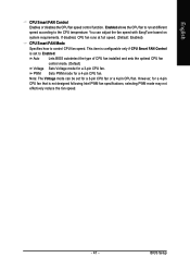
...to 200 MHz. GA-946GMX-S2 Motherboard - 48 - Enabled will allow for automated system reboot, or clear the CMOS values to reset the board to default values. (Default: Disabled) CPU Host Frequency (Mhz) Allows you install a CPU that the CPU frequency be configurable. English 2-9 Frequency/Voltage Control CMOS Setup Utility-Copyright (C) 1984-2007 Award Software Frequency/Voltage Control CPU Clock Ratio (Note) CPU Host Clock Control x CPU Host Frequency (Mhz) x PCI Express Frequency (Mhz) System Memory Multiplier (SPD) Memory Frequency (Mhz) 533 High Speed DRAM DLL Settings DDR2...
...to 200 MHz. GA-946GMX-S2 Motherboard - 48 - Enabled will allow for automated system reboot, or clear the CMOS values to reset the board to default values. (Default: Disabled) CPU Host Frequency (Mhz) Allows you install a CPU that the CPU frequency be configurable. English 2-9 Frequency/Voltage Control CMOS Setup Utility-Copyright (C) 1984-2007 Award Software Frequency/Voltage Control CPU Clock Ratio (Note) CPU Host Clock Control x CPU Host Frequency (Mhz) x PCI Express Frequency (Mhz) System Memory Multiplier (SPD) Memory Frequency (Mhz) 533 High Speed DRAM DLL Settings DDR2...

Manual
Page 52
... Saving CMOS Setup Utility-Copyright (C) 1984-2007 Award Software ` Standard CMOS Features ` Advanced BIOS Features ` Integrated Peripherals ` Power Management Setup ` PnP/PCI Configurations ` PC Health Status ` Frequency/Voltage Control ESC: Quit F8: Q-Flash Load Fail-Safe Defaults Load Optimized Defaults Set Supervisor Password Quit Without Saving (SYe/tNU)?seNr Password Save & Exit Setup Exit Without Saving KLJI: Select Item F10: Save & Exit Setup Abandon all Data F11: Save CMOS to BIOS F12: Load CMOS from BIOS Save Data to the BIOS Setup Main Menu. GA-946GMX-S2 Motherboard...
... Saving CMOS Setup Utility-Copyright (C) 1984-2007 Award Software ` Standard CMOS Features ` Advanced BIOS Features ` Integrated Peripherals ` Power Management Setup ` PnP/PCI Configurations ` PC Health Status ` Frequency/Voltage Control ESC: Quit F8: Q-Flash Load Fail-Safe Defaults Load Optimized Defaults Set Supervisor Password Quit Without Saving (SYe/tNU)?seNr Password Save & Exit Setup Exit Without Saving KLJI: Select Item F10: Save & Exit Setup Abandon all Data F11: Save CMOS to BIOS F12: Load CMOS from BIOS Save Data to the BIOS Setup Main Menu. GA-946GMX-S2 Motherboard...
Manual
Page 65
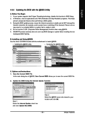
... a BIOS update. 3. Options and Instructions: 1. Save the Current BIOS File In the main dialog box of @BIOS, Save Current BIOS allows you to install @BIOS. • Installing the @BIOS utility. • Accessing the @BIOS utility. During the BIOS update process, ensure the Internet connection is unable to start. 4. B. English 4-2-2 Updating the BIOS with the motherboard to save the current BIOS file. 2. GIGABYTE product warranty does not cover any BIOS damage or system failure resulting from an inadequate BIOS flashing. Installing and Using @BIOS: Use the driver...
... a BIOS update. 3. Options and Instructions: 1. Save the Current BIOS File In the main dialog box of @BIOS, Save Current BIOS allows you to install @BIOS. • Installing the @BIOS utility. • Accessing the @BIOS utility. During the BIOS update process, ensure the Internet connection is unable to start. 4. B. English 4-2-2 Updating the BIOS with the motherboard to save the current BIOS file. 2. GIGABYTE product warranty does not cover any BIOS damage or system failure resulting from an inadequate BIOS flashing. Installing and Using @BIOS: Use the driver...
Manual
Page 77
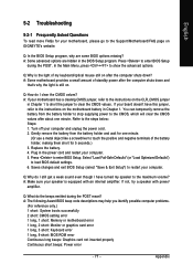
... advanced options are some BIOS options missing? Replace the battery. 4. A: The following Award BIOS beep code descriptions may help you identify possible computer problems. (For reference only.) 1 short: System boots successfully 2 short: CMOS setting error 1 long, 1 short: Memory or motherboard error 1 long, 2 short: Monitor or graphics card error 1 long, 3 short: Keyboard error 1 long, 9 short: BIOS ROM error Continuous long beeps: Graphics card not inserted properly Continuous short beeps: Power error - 77 - In the Main Menu, press + to the instructions on the CLR_CMOS jumper in...
... advanced options are some BIOS options missing? Replace the battery. 4. A: The following Award BIOS beep code descriptions may help you identify possible computer problems. (For reference only.) 1 short: System boots successfully 2 short: CMOS setting error 1 long, 1 short: Memory or motherboard error 1 long, 2 short: Monitor or graphics card error 1 long, 3 short: Keyboard error 1 long, 9 short: BIOS ROM error Continuous long beeps: Graphics card not inserted properly Continuous short beeps: Power error - 77 - In the Main Menu, press + to the instructions on the CLR_CMOS jumper in...


