Manual
Page 1
GA-946GMX-S2 LGA775 socket motherboard for Intel® CoreTM processor family/ Intel® Pentium® processor family/Intel® Celeron® processor family User's Manual Rev. 1001 12ME-946GMX2R-1001R * The WEEE marking on the product indicates this product must not be disposed of with user's other household waste and must be handed over to a designated collection point for the recycling of waste electrical and electronic equipment!! * The WEEE marking applies only in European Union's member states.
GA-946GMX-S2 LGA775 socket motherboard for Intel® CoreTM processor family/ Intel® Pentium® processor family/Intel® Celeron® processor family User's Manual Rev. 1001 12ME-946GMX2R-1001R * The WEEE marking on the product indicates this product must not be disposed of with user's other household waste and must be handed over to a designated collection point for the recycling of waste electrical and electronic equipment!! * The WEEE marking applies only in European Union's member states.
Manual
Page 2
Motherboard GA-946GMX-S2 Apr. 13, 2007 Motherboard GA-946GMX-S2 Apr. 13, 2007
Motherboard GA-946GMX-S2 Apr. 13, 2007 Motherboard GA-946GMX-S2 Apr. 13, 2007
Manual
Page 3
... for technical information. Example: All rights reserved. No part of the motherboard is designated by GIGABYTE without GIGABYTE's prior written permission. For example, "REV: 1.0" means the revision of this : "REV: X.X." GIGABYTE UNITED INC. Disclaimer Information in this product, GIGABYTE provides the following types of GIGABYTE. Changes to the specifications and features in this manual are legally...
... for technical information. Example: All rights reserved. No part of the motherboard is designated by GIGABYTE without GIGABYTE's prior written permission. For example, "REV: 1.0" means the revision of this : "REV: X.X." GIGABYTE UNITED INC. Disclaimer Information in this product, GIGABYTE provides the following types of GIGABYTE. Changes to the specifications and features in this manual are legally...
Manual
Page 4
Table of Contents OptionalItems ...6 Box Contents ...6 GA-946GMX-S2 Motherboard Layout 7 Block Diagram ...8 Chapter 1 Hardware Installation 9 1-1 Installation Precautions 9 1-2 Product Specifications 10 1-3 Installing the CPU and CPU Cooler 12 1-3-1 Installing the CPU 12 1-3-2 Installing the CPU ...
Table of Contents OptionalItems ...6 Box Contents ...6 GA-946GMX-S2 Motherboard Layout 7 Block Diagram ...8 Chapter 1 Hardware Installation 9 1-1 Installation Precautions 9 1-2 Product Specifications 10 1-3 Installing the CPU and CPU Cooler 12 1-3-1 Installing the CPU 12 1-3-2 Installing the CPU ...
Manual
Page 6
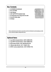
Box Contents GA-946GMX-S2 motherboard Driver CD-ROM User's Manual Intel® LGA775 CPU Installation Guide One IDE cable and one floppy disk drive cable One SATA 3Gb/s cables I/O Shield ...
Box Contents GA-946GMX-S2 motherboard Driver CD-ROM User's Manual Intel® LGA775 CPU Installation Guide One IDE cable and one floppy disk drive cable One SATA 3Gb/s cables I/O Shield ...
Manual
Page 7
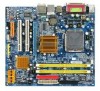
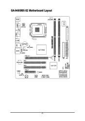
GA-946GMX-S2 Motherboard Layout KB_MS CPU_FAN IT8718 LGA775 ATX_12V FDD GA-946GMX-S2 LPT LAN VGA COMA R_USB BATTERY USB CLR_CMOS AUDIO SYS_FAN F_AUDIO PCIE_16 Intel® 946GZ PCI1 RTL8110SC PCI2 CODEC PCIE_4 SPDIF_IO CD_IN Intel® ICH7 MBIOS COMB F_USB1 F_USB2 IDE ATX CI SATAII0 SATAII2 SATAII1 SATAII3 DDRII1 DDRII2 PWR_LED F_PANEL - 7 -
GA-946GMX-S2 Motherboard Layout KB_MS CPU_FAN IT8718 LGA775 ATX_12V FDD GA-946GMX-S2 LPT LAN VGA COMA R_USB BATTERY USB CLR_CMOS AUDIO SYS_FAN F_AUDIO PCIE_16 Intel® 946GZ PCI1 RTL8110SC PCI2 CODEC PCIE_4 SPDIF_IO CD_IN Intel® ICH7 MBIOS COMB F_USB1 F_USB2 IDE ATX CI SATAII0 SATAII2 SATAII1 SATAII3 DDRII1 DDRII2 PWR_LED F_PANEL - 7 -

Manual
Page 9
...product, please verify that all cables and power connectors of your dealer. These stickers are connected tightly and securely. • When handling the motherboard, avoid touching any installation steps or have it on top of an antistatic pad or within the computer casing. • Do not place ... are required for warranty validation. • Always remove the AC power by your hardware components are connected. • To prevent damage to the motherboard, do not have an ESD wrist strap, keep your hands dry and first touch a metal object to eliminate static electricity. • Prior to...
...product, please verify that all cables and power connectors of your dealer. These stickers are connected tightly and securely. • When handling the motherboard, avoid touching any installation steps or have it on top of an antistatic pad or within the computer casing. • Do not place ... are required for warranty validation. • Always remove the AC power by your hardware components are connected. • To prevent damage to the motherboard, do not have an ESD wrist strap, keep your hands dry and first touch a metal object to eliminate static electricity. • Prior to...
Manual
Page 10
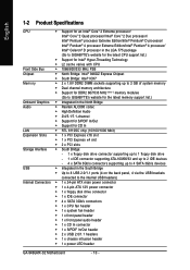
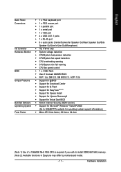
...174; Pentium® 4 processor/ Intel® Celeron® D processor in the LGA 775 package (Go to GIGABYTE's website for the latest CPU support list.) Š Support for Intel® Hyper-Threading Technology Š L2 ...Dual channel memory architecture Š Support for DDR2 667/533 MHz (Note 1) memory modules (Go to GIGABYTE's website for the latest memory support list.) Onboard Graphics Š Integrated in the North Bridge Audio Š...In/Out header Š 2 x USB 2.0/1.1 headers Š 1 x chassis intrusion header Š 1 x power LED header GA-946GMX-S2 Motherboard - 10 -
...174; Pentium® 4 processor/ Intel® Celeron® D processor in the LGA 775 package (Go to GIGABYTE's website for the latest CPU support list.) Š Support for Intel® Hyper-Threading Technology Š L2 ...Dual channel memory architecture Š Support for DDR2 667/533 MHz (Note 1) memory modules (Go to GIGABYTE's website for the latest memory support list.) Onboard Graphics Š Integrated in the North Bridge Audio Š...In/Out header Š 2 x USB 2.0/1.1 headers Š 1 x chassis intrusion header Š 1 x power LED header GA-946GMX-S2 Motherboard - 10 -
Manual
Page 11
... Recovery2 Š Support for Virtual Dual BIOS Š Norton Internet Security (OEM version) Š Support for Microsoft® Windows® Vista/XP/2000 (Go to GIGABYTE's website for operating system support information.) Š Micro ATX form factor; 22.0cm x 24.4cm (Note 1) Use of a 1066/800 MHz FSB CPU is required...
... Recovery2 Š Support for Virtual Dual BIOS Š Norton Internet Security (OEM version) Š Support for Microsoft® Windows® Vista/XP/2000 (Go to GIGABYTE's website for operating system support information.) Š Micro ATX form factor; 22.0cm x 24.4cm (Note 1) Use of a 1066/800 MHz FSB CPU is required...
Manual
Page 12
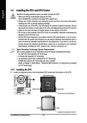
...unplug the power cord from the power outlet before you begin to install the CPU: • Make sure that the motherboard supports the CPU. (Go to GIGABYTE's website for instructions on enabling the HT Technology.) 1-3-1 Installing the CPU A. LGA775 CPU Socket Alignment Key LGA 775 CPU...and CPU Cooler Read the following guidelines before installing the CPU to prevent hardware damage. • Locate the pin one of the CPU Socket GA-946GMX-S2 Motherboard Notch - 12 - The CPU cannot be set the frequency beyond hardware specifications since it enabled (Refer to Chapter 2, "BIOS Setup," "...
...unplug the power cord from the power outlet before you begin to install the CPU: • Make sure that the motherboard supports the CPU. (Go to GIGABYTE's website for instructions on enabling the HT Technology.) 1-3-1 Installing the CPU A. LGA775 CPU Socket Alignment Key LGA 775 CPU...and CPU Cooler Read the following guidelines before installing the CPU to prevent hardware damage. • Locate the pin one of the CPU Socket GA-946GMX-S2 Motherboard Notch - 12 - The CPU cannot be set the frequency beyond hardware specifications since it enabled (Refer to Chapter 2, "BIOS Setup," "...

Manual
Page 13
... sure to turn off the computer and unplug the power cord from the power outlet to prevent damage to correctly install the CPU into the motherboard CPU socket. Step 2: Remove the protective socket cover. Step 3: Lift the metal load plate on the CPU socket. Step 4: Hold the CPU with the socket...
... sure to turn off the computer and unplug the power cord from the power outlet to prevent damage to correctly install the CPU into the motherboard CPU socket. Step 2: Remove the protective socket cover. Step 3: Lift the metal load plate on the CPU socket. Step 4: Hold the CPU with the socket...
Manual
Page 14
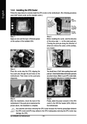
... between the CPU cooler and CPU may damage the CPU. Step 4: You should hear a "click" when pushing down on the push pins diagonally. GA-946GMX-S2 Motherboard - 14 - Push down each push pin. If the push pin is inserted as the example cooler.) Step 1: Apply an even and thin layer ..., the installation is to install.) Step 3: Place the cooler atop the CPU, aligning the four push pins through the pin holes on the motherboard. English 1-3-2 Installing the CPU Cooler Follow the steps below to your CPU cooler installation manual for instructions on installing the cooler.) Step 5: After...
... between the CPU cooler and CPU may damage the CPU. Step 4: You should hear a "click" when pushing down on the push pins diagonally. GA-946GMX-S2 Motherboard - 14 - Push down each push pin. If the push pin is inserted as the example cooler.) Step 1: Apply an even and thin layer ..., the installation is to install.) Step 3: Place the cooler atop the CPU, aligning the four push pins through the pin holes on the motherboard. English 1-3-2 Installing the CPU Cooler Follow the steps below to your CPU cooler installation manual for instructions on installing the cooler.) Step 5: After...
Manual
Page 15
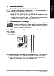
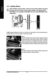
...if only one DDR2 memory module is recommended that memory of the same capacity, brand, speed, and chips be used . (Go to GIGABYTE's website for the latest memory support list.) • Always turn off the computer and unplug the power cord from the power outlet before... to chipset limitation, read the following guidelines before you begin to insert the memory, switch the direction. 1-4-1 Dual Channel Memory Configuration This motherboard provides two DDR2 memory sockets and supports Dual Channel Technology. When enabling Dual Channel mode with two memory modules, it is installed. 2. ...
...if only one DDR2 memory module is recommended that memory of the same capacity, brand, speed, and chips be used . (Go to GIGABYTE's website for the latest memory support list.) • Always turn off the computer and unplug the power cord from the power outlet before... to chipset limitation, read the following guidelines before you begin to insert the memory, switch the direction. 1-4-1 Dual Channel Memory Configuration This motherboard provides two DDR2 memory sockets and supports Dual Channel Technology. When enabling Dual Channel mode with two memory modules, it is installed. 2. ...
Manual
Page 16
Step 1: Note the orientation of the memory, push down on the top edge of the memory module. GA-946GMX-S2 Motherboard - 16 - Place the memory module on this motherboard. DDR2 DIMMs are not compatible to DDR DIMMs. Be sure to install DDR2 DIMMs on the socket. Notch DDR2 DIMM A DDR2 memory module has a notch, ...
Step 1: Note the orientation of the memory, push down on the top edge of the memory module. GA-946GMX-S2 Motherboard - 16 - Place the memory module on this motherboard. DDR2 DIMMs are not compatible to DDR DIMMs. Be sure to install DDR2 DIMMs on the socket. Notch DDR2 DIMM A DDR2 memory module has a notch, ...
Manual
Page 17
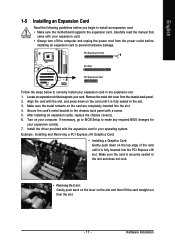
... your computer. Hardware Installation Remove the metal slot cover from the power outlet before you begin to install an expansion card: • Make sure the motherboard supports the expansion card. Secure the card's metal bracket to the chassis back panel with the expansion card in the slot. 3. Align the card with...
... your computer. Hardware Installation Remove the metal slot cover from the power outlet before you begin to install an expansion card: • Make sure the motherboard supports the expansion card. Secure the card's metal bracket to the chassis back panel with the expansion card in the slot. 3. Align the card with...
Manual
Page 18
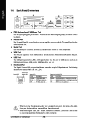
.... Use this port. Connect the monitor's VGA cable to a back panel connector, first remove the cable from your device and then remove it from the motherboard. • When removing the cable, pull it side to side to connect devices such as a printer, scanner and etc. RJ-45 LAN Port The Gigabit... The VGA port supports a 15-pin VGA connector (D-Sub). Parallel Port Use the parallel port to connect devices such as a mouse, modem or other peripherals. GA-946GMX-S2 Motherboard - 18 -
.... Use this port. Connect the monitor's VGA cable to a back panel connector, first remove the cable from your device and then remove it from the motherboard. • When removing the cable, pull it side to side to connect devices such as a printer, scanner and etc. RJ-45 LAN Port The Gigabit... The VGA port supports a 15-pin VGA connector (D-Sub). Parallel Port Use the parallel port to connect devices such as a mouse, modem or other peripherals. GA-946GMX-S2 Motherboard - 18 -
Manual
Page 20
... sure to the connector on the motherboard. Unplug the power cord from the power outlet to prevent damage to the devices. • After installing the device and before connecting external devices: • First make sure the device cable has been securely attached to turn off the devices and your computer. GA-946GMX-S2 Motherboard - 20 -
... sure to the connector on the motherboard. Unplug the power cord from the power outlet to prevent damage to the devices. • After installing the device and before connecting external devices: • First make sure the device cable has been securely attached to turn off the devices and your computer. GA-946GMX-S2 Motherboard - 20 -

Manual
Page 21
... not connected, the computer will not start. • To meet expansion requirements, it is turned off and all the components on the motherboard. Do not insert the power supply cable into pins under the protective cover when using a 2x12 power supply, remove the protective cover from... the main power connector on the motherboard. Hardware Installation If a power supply is used that can lead to all devices are properly installed. Before connecting the power connector, first ...
... not connected, the computer will not start. • To meet expansion requirements, it is turned off and all the components on the motherboard. Do not insert the power supply cable into pins under the protective cover when using a 2x12 power supply, remove the protective cover from... the main power connector on the motherboard. Hardware Installation If a power supply is used that can lead to all devices are properly installed. Before connecting the power connector, first ...
Manual
Page 22
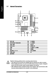
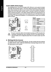
...your CPU and system from overheating. A red power connector wire indicates a positive connection and requires a +12V voltage. The motherboard supports CPU fan speed control, which requires the use of floppy disk drives supported are designed with fan speed control design. ... may result in the correct orientation. Do not place a jumper cap on the connector. 34 33 GA-946GMX-S2 Motherboard 2 1 - 22 - CPU_FAN : Pin No. English 3/4) CPU_FAN/SYS_FAN (Fan Headers) The motherboard has a 4-pin CPU fan header (CPU_FAN) and a 3-pin system fan header (SYS_FAN). The ...
...your CPU and system from overheating. A red power connector wire indicates a positive connection and requires a +12V voltage. The motherboard supports CPU fan speed control, which requires the use of floppy disk drives supported are designed with fan speed control design. ... may result in the correct orientation. Do not place a jumper cap on the connector. 34 33 GA-946GMX-S2 Motherboard 2 1 - 22 - CPU_FAN : Pin No. English 3/4) CPU_FAN/SYS_FAN (Fan Headers) The motherboard has a 4-pin CPU fan header (CPU_FAN) and a 3-pin system fan header (SYS_FAN). The ...
Manual
Page 24
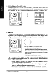
... cord. 2. Pin No. English 8) PWR_LED (System Power LED Header) This header can be used to connect a system power LED on when the system is operating. GA-946GMX-S2 Motherboard - 24 - You may be handled in accordance with an equivalent one minute. (Or use a metal object like a screwdriver to replace the battery by removing the...
... cord. 2. Pin No. English 8) PWR_LED (System Power LED Header) This header can be used to connect a system power LED on when the system is operating. GA-946GMX-S2 Motherboard - 24 - You may be handled in accordance with an equivalent one minute. (Or use a metal object like a screwdriver to replace the battery by removing the...


