Manual
Page 4
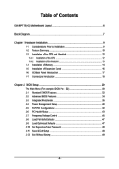
... 1-3-1 Installation of the CPU 12 1-3-2 Installation of the Heatsink 13 1-4 Installation of Memory 14 1-5 Installation of Expansion Cards 16 1-6 I/O Back Panel Introduction 17 1-7 Connectors Introduction 18 Chapter 2 BIOS Setup 29 The Main Menu (For example: BIOS Ver. : E2 30 2-1 Standard CMOS Features 32 2-2 Advanced BIOS Features 34 2-3 Integrated Peripherals 36 2-4 Power Management Setup 40 2-5 PnP/PCI Configurations 42 2-6 PC Health Status 43 2-7 Frequency/Voltage Control 45 2-8 Load Fail-Safe Defaults 47 2-9 Load Optimized Defaults 47 2-10 Set Supervisor/User Password 48...
... 1-3-1 Installation of the CPU 12 1-3-2 Installation of the Heatsink 13 1-4 Installation of Memory 14 1-5 Installation of Expansion Cards 16 1-6 I/O Back Panel Introduction 17 1-7 Connectors Introduction 18 Chapter 2 BIOS Setup 29 The Main Menu (For example: BIOS Ver. : E2 30 2-1 Standard CMOS Features 32 2-2 Advanced BIOS Features 34 2-3 Integrated Peripherals 36 2-4 Power Management Setup 40 2-5 PnP/PCI Configurations 42 2-6 PC Health Status 43 2-7 Frequency/Voltage Control 45 2-8 Load Fail-Safe Defaults 47 2-9 Load Optimized Defaults 47 2-10 Set Supervisor/User Password 48...
Manual
Page 15
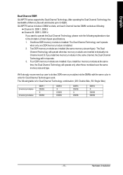
... memory size and type. GA-8IP775 series includes 4 DIMM sockets, and each Channel has two DIMM sockets as following: Channel A : DDR 1, DDR 2 Channel B : DDR 3, DDR 4 If you install two memory modules in the same channel, the Dual Channel Technology will operate when two memory modules are installed (the same memory size and type): The Dual Channel Technology will not operate. 3. One/three DDR memory module is installed: The Dual Channel Technology can't operate when only one DDR memory module is for Dual Channel Technology...
... memory size and type. GA-8IP775 series includes 4 DIMM sockets, and each Channel has two DIMM sockets as following: Channel A : DDR 1, DDR 2 Channel B : DDR 3, DDR 4 If you install two memory modules in the same channel, the Dual Channel Technology will operate when two memory modules are installed (the same memory size and type): The Dual Channel Technology will not operate. 3. One/three DDR memory module is installed: The Dual Channel Technology can't operate when only one DDR memory module is for Dual Channel Technology...
Manual
Page 20
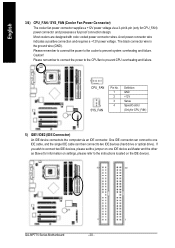
... power voltage. One IDE connector can then connect to the instructions located on the IDE device). 40 39 2 1 GA-8IP775 Series Motherboard - 20 - If you wish to connect two IDE devices, please set the jumper on one IDE cable, and the single IDE cable can connect to one IDE device as Master and the other as Slave (for CPU_FAN) power connector and possesses a ful-proof connection design. Please remember to connect the power to the CPU fan to prevent CPU overheating and failure. 1 CPU_ FAN...
... power voltage. One IDE connector can then connect to the instructions located on the IDE device). 40 39 2 1 GA-8IP775 Series Motherboard - 20 - If you wish to connect two IDE devices, please set the jumper on one IDE cable, and the single IDE cable can connect to one IDE device as Master and the other as Slave (for CPU_FAN) power connector and possesses a ful-proof connection design. Please remember to connect the power to the CPU fan to prevent CPU overheating and failure. 1 CPU_ FAN...
Manual
Page 21
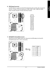
... BIOS setting for the Serial ATA and install the proper driver in order to the pin1 position. 34 33 2 1 7) SATA0/SATA1 (Serial ATAConnector) Serial ATA can provide 150MB/s transfer rate. Definition 1 GND 7 2 TXP 1 3 TXN 4 GND 5 RXN 6 RXP 7 GND - 21 - The types of the cable connects to the FDD drive. Please connect the red power connector wire to work properly. Hardware Installation English 6) FDD (Floppy Connector) The FDD connector is used to connect...
... BIOS setting for the Serial ATA and install the proper driver in order to the pin1 position. 34 33 2 1 7) SATA0/SATA1 (Serial ATAConnector) Serial ATA can provide 150MB/s transfer rate. Definition 1 GND 7 2 TXP 1 3 TXN 4 GND 5 RXN 6 RXP 7 GND - 21 - The types of the cable connects to the FDD drive. Please connect the red power connector wire to work properly. Hardware Installation English 6) FDD (Floppy Connector) The FDD connector is used to connect...
Manual
Page 30
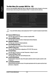
... configuration. CMOS Setup Utility-Copyright (C) 1984-2004 Award Software ` Standard CMOS Features ` Advanced BIOS Features ` Integrated Peripherals ` Power Management Setup ` PnP/PCI Configurations ` PC Health Status ` Frequency/Voltage Control ESC: Quit F8: Q-Flash Load Fail-Safe Defaults Load Optimized Defaults Set Supervisor Password Set User Password Save & Exit Setup Exit Without Saving KLJI: Select Item F10: Save & Exit Setup Time, Date, Hard Disk Type... GA-8IP775 Series Motherboard - 30 - If you can't find the setting you enter Award BIOS CMOS Setup Utility, the Main Menu...
... configuration. CMOS Setup Utility-Copyright (C) 1984-2004 Award Software ` Standard CMOS Features ` Advanced BIOS Features ` Integrated Peripherals ` Power Management Setup ` PnP/PCI Configurations ` PC Health Status ` Frequency/Voltage Control ESC: Quit F8: Q-Flash Load Fail-Safe Defaults Load Optimized Defaults Set Supervisor Password Set User Password Save & Exit Setup Exit Without Saving KLJI: Select Item F10: Save & Exit Setup Time, Date, Hard Disk Type... GA-8IP775 Series Motherboard - 30 - If you can't find the setting you enter Award BIOS CMOS Setup Utility, the Main Menu...
Manual
Page 32
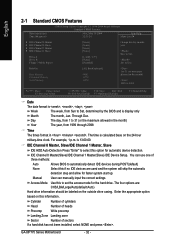
...) IDE Device Setup. GA-8IP775 Series Motherboard - 32 - Week Month The week, from 1999 through 2098 Time The times format in . Through Dec. IDE Channel 0 Master, Slave/IDE Channel 1 Master, Slave IDE HDD Auto-Detection Press "Enter" to select this if no IDE devices are : CHS/LBA/Large/Auto(default:Auto) Hard drive information should be labeled on the outside drive casing. Enter the appropriate option based on the 24-hour military-time clock. Holt On Base Memory...
...) IDE Device Setup. GA-8IP775 Series Motherboard - 32 - Week Month The week, from 1999 through 2098 Time The times format in . Through Dec. IDE Channel 0 Master, Slave/IDE Channel 1 Master, Slave IDE HDD Auto-Detection Press "Enter" to select this if no IDE devices are : CHS/LBA/Large/Auto(default:Auto) Hard drive information should be labeled on the outside drive casing. Enter the appropriate option based on the 24-hour military-time clock. Holt On Base Memory...
Manual
Page 34
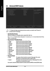
...list. ZIP Select your boot device priority by USB-HDD. USB-CDROM Select your boot device priority by Hard Disk. USB-HDD Select your boot device priority by USB-ZIP. If you install the Intel® Pentium® 4 processor with HT Technology. USB-ZIP Select your boot device priority by USB-CDROM. English 2-2 Advanced BIOS Features CMOS Setup Utility-Copyright (C) 1984-2004 Award Software Advanced BIOS Features X Hard Disk Boot Priority First Boot Device Second Boot Device Third Boot Device Password Check # CPU Hyper-Threading Limit CPUID Max. to 3 [Press Enter] [Floppy...
...list. ZIP Select your boot device priority by USB-HDD. USB-CDROM Select your boot device priority by Hard Disk. USB-HDD Select your boot device priority by USB-ZIP. If you install the Intel® Pentium® 4 processor with HT Technology. USB-ZIP Select your boot device priority by USB-CDROM. English 2-2 Advanced BIOS Features CMOS Setup Utility-Copyright (C) 1984-2004 Award Software Advanced BIOS Features X Hard Disk Boot Priority First Boot Device Second Boot Device Third Boot Device Password Check # CPU Hyper-Threading Limit CPUID Max. to 3 [Press Enter] [Floppy...
Manual
Page 37
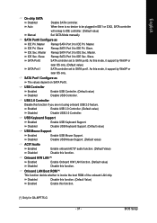
.... Onboard LAN Boot ROM (*) This function decide whether to IDE Pri. IDE Pri. SATA Port0 SATA controller set to SATA port0. Disabled Disable USB Keyboard Support. (Default value) USB Mouse Support Enabled Enable USB Mouse Support. IDE Sec. USB 2.0 Controller Disable this function. Auto When there is no device to be plugged in IDE1 or IDE2, SATA controller will remap to IDE Pri. Slave Remap SATA Port 0 to IDE controller. (Default value) Manual Set SATA Mode manually. Slave Remap SATA Port 0 to IDE Sec. SATA Port1 Configure as IDE Pri. BIOS Setup SATA...
.... Onboard LAN Boot ROM (*) This function decide whether to IDE Pri. IDE Pri. SATA Port0 SATA controller set to SATA port0. Disabled Disable USB Keyboard Support. (Default value) USB Mouse Support Enabled Enable USB Mouse Support. IDE Sec. USB 2.0 Controller Disable this function. Auto When there is no device to be plugged in IDE1 or IDE2, SATA controller will remap to IDE Pri. Slave Remap SATA Port 0 to IDE controller. (Default value) Manual Set SATA Mode manually. Slave Remap SATA Port 0 to IDE Sec. SATA Port1 Configure as IDE Pri. BIOS Setup SATA...
Manual
Page 40
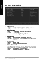
...PME Event Wake Up Disabled Disable this function. Enabled Enable Modem Ring on/wake on Lan function. Disabled Disable Modem Ring on/wake on Lan. (Default value) GA-8IP775 Series Motherboard - 40 - If use single color LED, power LED will turn off instantly. (Default value) Delay 4 Sec. Enter suspend if button is pressed less than 4 sec. English 2-4 Power Management Setup CMOS Setup Utility-Copyright (C) 1984-2004 Award Software Power Management Setup ACPI Suspend Type Power LED in S1 state Blinking In standby mode(S1), power LED will blink. (Default value) Dual/OFF...
...PME Event Wake Up Disabled Disable this function. Enabled Enable Modem Ring on/wake on Lan function. Disabled Disable Modem Ring on/wake on Lan. (Default value) GA-8IP775 Series Motherboard - 40 - If use single color LED, power LED will turn off instantly. (Default value) Delay 4 Sec. Enter suspend if button is pressed less than 4 sec. English 2-4 Power Management Setup CMOS Setup Utility-Copyright (C) 1984-2004 Award Software Power Management Setup ACPI Suspend Type Power LED in S1 state Blinking In standby mode(S1), power LED will blink. (Default value) Dual/OFF...
Manual
Page 45
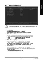
... is set "CPU Host Frequency" to 355MHz. If you use FSB800 Pentium 4 processor, please set to SRC clock. SRC over clock may make Serial ATA device function can't work properly. English 2-7 Frequency/Voltage Control CMOS Setup Utility-Copyright (C) 1984-2004 Award Software Frequency/Voltage Control CPU Clock Ratio CPU Host Clock Control x CPU Host Frequency (Mhz) x AGP/PCI/SRC Fixed Memory Frequency For Memory Frequency (Mhz) AGP/PCI/SRC Frequency (Mhz) DIMM OverVoltage Control AGP OverVoltage Control CPU Voltage Control Normal CPU Vcore [15X] [Disabled] 100 66/33/100 [Auto] 266...
... is set "CPU Host Frequency" to 355MHz. If you use FSB800 Pentium 4 processor, please set to SRC clock. SRC over clock may make Serial ATA device function can't work properly. English 2-7 Frequency/Voltage Control CMOS Setup Utility-Copyright (C) 1984-2004 Award Software Frequency/Voltage Control CPU Clock Ratio CPU Host Clock Control x CPU Host Frequency (Mhz) x AGP/PCI/SRC Fixed Memory Frequency For Memory Frequency (Mhz) AGP/PCI/SRC Frequency (Mhz) DIMM OverVoltage Control AGP OverVoltage Control CPU Voltage Control Normal CPU Vcore [15X] [Disabled] 100 66/33/100 [Auto] 266...
Manual
Page 46
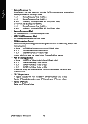
...'t boot, clear CMOS to the memory may cause your CPU Vcore Voltage. Normal CPU Vcore Display your system broken. CPU Voltage Control Supports adjustable CPU Vcore from 0.8375V to 1.6000V. (Default value: Normal) Warning: CPU may damage to +0.3V. Auto Set Memory frequency by DRAM SPD data. (Default value) for Over_Clock. For power End-User use only! AGP/PCI/SRC Frequency (Mhz) The values depend on "CPU Host Frequency(Mhz)" item. Normal Set DIMM OverVoltage Control to Normal. (Default value) +0.1V Set...
...'t boot, clear CMOS to the memory may cause your CPU Vcore Voltage. Normal CPU Vcore Display your system broken. CPU Voltage Control Supports adjustable CPU Vcore from 0.8375V to 1.6000V. (Default value: Normal) Warning: CPU may damage to +0.3V. Auto Set Memory frequency by DRAM SPD data. (Default value) for Over_Clock. For power End-User use only! AGP/PCI/SRC Frequency (Mhz) The values depend on "CPU Host Frequency(Mhz)" item. Normal Set DIMM OverVoltage Control to Normal. (Default value) +0.1V Set...
Manual
Page 48
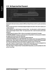
... and not enter a password. GA-8IP775 Series Motherboard - 48 - The BIOS Setup program allows you are prompted to confirm the password being disabled. You may access all BIOS Setup program function. English 2-10 Set Supervisor/User Password CMOS Setup Utility-Copyright (C) 1984-2004 Award Software ` Standard CMOS Features ` Advanced BIOS Features ` Integrated Peripherals ` Power Management Setup ` PnP/PCI ConfigurationEsnter Password: ` PC Health Status ` Frequency/Voltage Control Load Fail-Safe Defaults Load Optimized Defaults Set Supervisor Password Set User Password Save & Exit...
... and not enter a password. GA-8IP775 Series Motherboard - 48 - The BIOS Setup program allows you are prompted to confirm the password being disabled. You may access all BIOS Setup program function. English 2-10 Set Supervisor/User Password CMOS Setup Utility-Copyright (C) 1984-2004 Award Software ` Standard CMOS Features ` Advanced BIOS Features ` Integrated Peripherals ` Power Management Setup ` PnP/PCI ConfigurationEsnter Password: ` PC Health Status ` Frequency/Voltage Control Load Fail-Safe Defaults Load Optimized Defaults Set Supervisor Password Set User Password Save & Exit...
Manual
Page 51
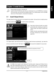
... the installation guide. Click each item to install the driver manually or switch to the to install the drivers automatically. Some device drivers will auto start and show a question mark "?" Install Drivers After restarting your system automatically. Just select the drivers you want then click the "GO" button. Click "GO". We recommend that you install all components in "Universal Serial Bus controller" under Windows XP operating system, please use Windows Service Pack. After install Windows Service Pack...
... the installation guide. Click each item to install the driver manually or switch to the to install the drivers automatically. Some device drivers will auto start and show a question mark "?" Install Drivers After restarting your system automatically. Just select the drivers you want then click the "GO" button. Click "GO". We recommend that you install all components in "Universal Serial Bus controller" under Windows XP operating system, please use Windows Service Pack. After install Windows Service Pack...
Manual
Page 59
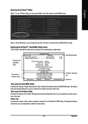
...CMOS Setup Utility-Copyright (C) 1984-2004 Award Software Standard CMOS Features Advanced BIOS Features Integrated Peripherals Power Management Setup PnP/PCI Configurations PC Health Status MB Intelligent Tweaker(M.I.T.) ESC: Quit F8: Dual BIOS/Q-Flash Select Language Load Fail-Safe Defaults Load Optimized Defaults Set Supervisor Password Set User Password Save & Exit Setup Exit Without Saving F3: Change Language F10: Save & Exit Setup Time, Date, Hard Disk Type... English Entering the Q-FlashTM utility: Step1: To use Q-Flash utility, you must press Del in the boot screen to enter BIOS...
...CMOS Setup Utility-Copyright (C) 1984-2004 Award Software Standard CMOS Features Advanced BIOS Features Integrated Peripherals Power Management Setup PnP/PCI Configurations PC Health Status MB Intelligent Tweaker(M.I.T.) ESC: Quit F8: Dual BIOS/Q-Flash Select Language Load Fail-Safe Defaults Load Optimized Defaults Set Supervisor Password Set User Password Save & Exit Setup Exit Without Saving F3: Change Language F10: Save & Exit Setup Time, Date, Hard Disk Type... English Entering the Q-FlashTM utility: Step1: To use Q-Flash utility, you must press Del in the boot screen to enter BIOS...
Manual
Page 60
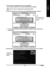
... entered the Q-Flash utility, please follow the steps below to update BIOS?" Dual BIOS Utility Boot From Main Bios Main ROM Type/Size SST 49LF004A Backup ROM Type/Size SST 49LF004A 512K 512K Wide Range Protection Disable R>>ea>d>in the Q-Flash menu and press Enter button. GA-8IP775 Series Motherboard - 60 - In this stage!! Press arrow buttons on your system at this example, we only download one BIOS file, 8KNXPU.Fba, is read, you previously downloaded to Floppy Enter : Run :Move ESC:Reset F10:Power Off BIOS file...
... entered the Q-Flash utility, please follow the steps below to update BIOS?" Dual BIOS Utility Boot From Main Bios Main ROM Type/Size SST 49LF004A Backup ROM Type/Size SST 49LF004A 512K 512K Wide Range Protection Disable R>>ea>d>in the Q-Flash menu and press Enter button. GA-8IP775 Series Motherboard - 60 - In this stage!! Press arrow buttons on your system at this example, we only download one BIOS file, 8KNXPU.Fba, is read, you previously downloaded to Floppy Enter : Run :Move ESC:Reset F10:Power Off BIOS file...
Manual
Page 61
... sure to update BIOS. Award Modular BIOS v6.00PG, An Energy Star Ally Copyright (C) 1984-2003, Award Software, Inc. English 3. The progress of updating BIOS will begin to update BIOS. Please do not take out the floppy disk when it will be displayed. Halt On Error Disable CPolpeyasMe apirneRssOaMnyDkaetya to cBoanctkiunpue Load Default Settings Save Settings to CMOS Q-Flash Utility Load Main BIOS from Floppy Load Backup BIOS from Floppy Save Main BIOS to Floppy Save Backup BIOS to enter SETUP / Dual BIOS / Q-Flash / F9 For Xpress Recovery 09...
... sure to update BIOS. Award Modular BIOS v6.00PG, An Energy Star Ally Copyright (C) 1984-2003, Award Software, Inc. English 3. The progress of updating BIOS will begin to update BIOS. Please do not take out the floppy disk when it will be displayed. Halt On Error Disable CPolpeyasMe apirneRssOaMnyDkaetya to cBoanctkiunpue Load Default Settings Save Settings to CMOS Q-Flash Utility Load Main BIOS from Floppy Load Backup BIOS from Floppy Save Main BIOS to Floppy Save Backup BIOS to enter SETUP / Dual BIOS / Q-Flash / F9 For Xpress Recovery 09...
Manual
Page 62
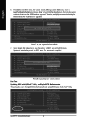
...Defaults Power Management Setup Save to load defaults. 7. English 6. Part Two: Updating BIOS with Q-FlashTM Utility on your keyboard to CMOS and EXIT (SYe/tNS)u?pYervisor Password PnP/PCI Configurations Set User Password PC Health Status Save & Exit Setup MB Intelligent Tweaker(M.I .T.) ESC: Quit F8: Q-Flash Top Performance Load Fail-Safe Defaults Load Optimized Defaults Set Supervisor Password Set User Password Save & Exit Setup Exit Without Saving F3: Change Language F10: Save & Exit Setup Time, Date, Hard Disk Type... CMOS Setup Utility-Copyright (C) 1984-2004 Award Software...
...Defaults Power Management Setup Save to load defaults. 7. English 6. Part Two: Updating BIOS with Q-FlashTM Utility on your keyboard to CMOS and EXIT (SYe/tNS)u?pYervisor Password PnP/PCI Configurations Set User Password PC Health Status Save & Exit Setup MB Intelligent Tweaker(M.I .T.) ESC: Quit F8: Q-Flash Top Performance Load Fail-Safe Defaults Load Optimized Defaults Set Supervisor Password Set User Password Save & Exit Setup Exit Without Saving F3: Change Language F10: Save & Exit Setup Time, Date, Hard Disk Type... CMOS Setup Utility-Copyright (C) 1984-2004 Award Software...
Manual
Page 65
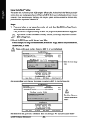
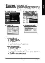
... @BIOS utility. @BIOS allows users to download the latest version of BIOS. Just select the desired @BIOS server to update their BIOS under Windows. Installation Complete and Run @BIOS Select @BIOS item than click Install Click Sart/ Programs/ GIGABYTE/@BIOS Fig 3. The @BIOS Utility Click " " Click "Update New BIOS" Fig 4. Update BIOS through Internet: a. Select the exact model name on your motherboard e. d. Please search for BIOS unzip file, downloading from internet or any other methods (such as: 8IP775.E2...
... @BIOS utility. @BIOS allows users to download the latest version of BIOS. Just select the desired @BIOS server to update their BIOS under Windows. Installation Complete and Run @BIOS Select @BIOS item than click Install Click Sart/ Programs/ GIGABYTE/@BIOS Fig 3. The @BIOS Utility Click " " Click "Update New BIOS" Fig 4. Update BIOS through Internet: a. Select the exact model name on your motherboard e. d. Please search for BIOS unzip file, downloading from internet or any other methods (such as: 8IP775.E2...
Manual
Page 75
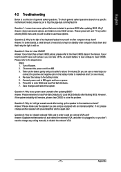
... questions based on a specific motherboard model, please log on to change another speaker with an internal amplifier. If your board has a Clear CMOS jumper, please refer to the Clear CMOS steps in the battery holder to enter BIOS and load Fail-Safe Defaults. 7. Turn off the on-board battery to leak voltage to add an external VGA card? Question 6: How do I cannot see these options. English 4-2 Troubleshooting Below is the light of my keyboard/optical mouse still on...
... questions based on a specific motherboard model, please log on to change another speaker with an internal amplifier. If your board has a Clear CMOS jumper, please refer to the Clear CMOS steps in the battery holder to enter BIOS and load Fail-Safe Defaults. 7. Turn off the on-board battery to leak voltage to add an external VGA card? Question 6: How do I cannot see these options. English 4-2 Troubleshooting Below is the light of my keyboard/optical mouse still on...
Manual
Page 76
... beep code 8, these beeps usually stand for reference purposes. gate A20 failure 7 beeps Processor exception interrupt error 8 beeps Display memory read/write failure 9 beeps ROM checksum error 10 beeps CMOS shutdown register read/write error 11 beeps Cache memory bad AWARD BIOS Beep Codes 1 short: System boots successfully 2 short: CMOS setting error 1 long 1 short: DRAM or M/B error 1 long 2 short: Monitor or display card error 1 long 3 short: Keyboard error 1 long 9 short: BIOS ROM error Continuous long beeps: DRAM error Continuous short beeps: Power error GA-8IP775 Series Motherboard...
... beep code 8, these beeps usually stand for reference purposes. gate A20 failure 7 beeps Processor exception interrupt error 8 beeps Display memory read/write failure 9 beeps ROM checksum error 10 beeps CMOS shutdown register read/write error 11 beeps Cache memory bad AWARD BIOS Beep Codes 1 short: System boots successfully 2 short: CMOS setting error 1 long 1 short: DRAM or M/B error 1 long 2 short: Monitor or display card error 1 long 3 short: Keyboard error 1 long 9 short: BIOS ROM error Continuous long beeps: DRAM error Continuous short beeps: Power error GA-8IP775 Series Motherboard...


