Manual
Page 1
GA-8IP775 Series Intel® Pentium® 4 LGA775 Processor Motherboard User's Manual Rev. 1003 12ME-8IP775-1003
GA-8IP775 Series Intel® Pentium® 4 LGA775 Processor Motherboard User's Manual Rev. 1003 12ME-8IP775-1003

Manual
Page 2
Motherboard GA-8IP775/GA-8IP775-G Sep. 10, 2004 Motherboard GA-8IP775/GA-8IP775-G Sep. 10, 2004
Motherboard GA-8IP775/GA-8IP775-G Sep. 10, 2004 Motherboard GA-8IP775/GA-8IP775-G Sep. 10, 2004
Manual
Page 4
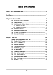
Table of Contents GA-8IP775(-G) Motherboard Layout 6 Block Diagram ...7 Chapter 1 Hardware Installation 9 1-1 Considerations Prior to Installation 9 1-2 Feature Summary 10 1-3 Installation of the CPU and Heatsink 12 1-3-1 Installation of the CPU 12 1-3-2 ...
Table of Contents GA-8IP775(-G) Motherboard Layout 6 Block Diagram ...7 Chapter 1 Hardware Installation 9 1-1 Considerations Prior to Installation 9 1-2 Feature Summary 10 1-3 Installation of the CPU and Heatsink 12 1-3-1 Installation of the CPU 12 1-3-2 ...
Manual
Page 6
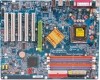
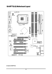
GA-8IP775(-G) Motherboard Layout KB_MS CPU_FAN ATX_12V COMA FDD ATX COMB LPT R_USB LGA775 IDE1 IDE2 GA-8IP775(-G) DDR1 DDR2 USB LAN (*) AUDIO CD_IN Intel® 865P Marvell F_AUDIO 8001 (*) AGP DDR4 DDR3 IT8712 CODEC SUR_CEN DUAL CHANNEL DDR PCI1 SATA P4 Titan PCI2 CI IR_CIR PCI3 PCI4 BIOS PCI5 GAME SPDIF_IO ICH5 SATA1 SATA0 BAT CLR_CMOS SYS_FAN INFO_LINK F_PANEL F_USB2 PWR_LED F_USB1 (*) Only for GA-8IP775-G. - 6 -
GA-8IP775(-G) Motherboard Layout KB_MS CPU_FAN ATX_12V COMA FDD ATX COMB LPT R_USB LGA775 IDE1 IDE2 GA-8IP775(-G) DDR1 DDR2 USB LAN (*) AUDIO CD_IN Intel® 865P Marvell F_AUDIO 8001 (*) AGP DDR4 DDR3 IT8712 CODEC SUR_CEN DUAL CHANNEL DDR PCI1 SATA P4 Titan PCI2 CI IR_CIR PCI3 PCI4 BIOS PCI5 GAME SPDIF_IO ICH5 SATA1 SATA0 BAT CLR_CMOS SYS_FAN INFO_LINK F_PANEL F_USB2 PWR_LED F_USB1 (*) Only for GA-8IP775-G. - 6 -
Manual
Page 9
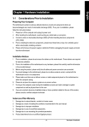
...Notices 1. Damage due to installation, please follow the instructions below: 1. Turning on top of the motherboard or any metal leads or connectors. 3. Damage due to be an unofficial Gigabyte product. - 9 - Please verify that all cables and power connectors are no leftover screws or ...metal components placed on the motherboard or within a electrostatic shielding container. 5. Prior to the installation of an...
...Notices 1. Damage due to installation, please follow the instructions below: 1. Turning on top of the motherboard or any metal leads or connectors. 3. Damage due to be an unofficial Gigabyte product. - 9 - Please verify that all cables and power connectors are no leftover screws or ...metal components placed on the motherboard or within a electrostatic shielding container. 5. Prior to the installation of an...
Manual
Page 10
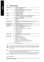
... Feature Summary M otherboard CPU Chip set Mem ory Slo ts IDE Connections FDD Connections Onboard SATA Peripherals Onboard LAN (*) Onboard Audio w GA-8IP775 Series Motherboard: GA-8IP 775-G/GA-8 IP775 w Supports the latest Intel® Pentium® 4 LGA775 CPU w Supports 800/533MHz FSB w L2 cache varies with CPU...shown as 3.xxGB memory during system startup. (Note 2) When FSB800 is selected as CPU frequency, memory will support DDR400 memory module. GA-8IP775 Series Motherboard - 10 - For example, 4 GB of memory is less than the stated amount. A FSB 533 Pentium 4 processor will support...
... Feature Summary M otherboard CPU Chip set Mem ory Slo ts IDE Connections FDD Connections Onboard SATA Peripherals Onboard LAN (*) Onboard Audio w GA-8IP775 Series Motherboard: GA-8IP 775-G/GA-8 IP775 w Supports the latest Intel® Pentium® 4 LGA775 CPU w Supports 800/533MHz FSB w L2 cache varies with CPU...shown as 3.xxGB memory during system startup. (Note 2) When FSB800 is selected as CPU frequency, memory will support DDR400 memory module. GA-8IP775 Series Motherboard - 10 - For example, 4 GB of memory is less than the stated amount. A FSB 533 Pentium 4 processor will support...
Manual
Page 12
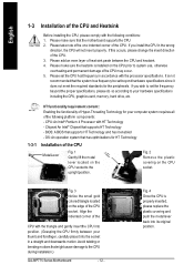
Please make sure that the motherboard supports the CPU. 2. Please set the CPU host frequency in accordance with HT Technology - CPU: An Intel® Pentium 4 Processor with the processor specifications. Fig. 4 ... proper specifications, please do so according to your computer system requires all gold colored triangle located on the CPU prior to the CPU during installation.) GA-8IP775 Series Motherboard - 12 - Fig. 3 Notice the sm all of the CPU. If this occurs, please change the insert direction of heat sink paste between your thumb...
Please make sure that the motherboard supports the CPU. 2. Please set the CPU host frequency in accordance with HT Technology - CPU: An Intel® Pentium 4 Processor with the processor specifications. Fig. 4 ... proper specifications, please do so according to your computer system requires all gold colored triangle located on the CPU prior to the CPU during installation.) GA-8IP775 Series Motherboard - 12 - Fig. 3 Notice the sm all of the CPU. If this occurs, please change the insert direction of heat sink paste between your thumb...
Manual
Page 14
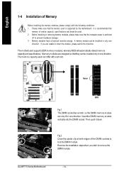
...are unable to prevent hardware damage. 3. Insert the DIM M memory module vertically into the DIMM socket. Then push it down. GA-8IP775 Series Motherboard - 14 - A memory module can only fit in one direction. Reverse the installation steps when you are designed so that memory... similar capacity, specifications and brand be installed in only one direction. Please make sure that the memory used . 2. The motherboard supports DDR memory modules, whereby BIOS will automatically detect memory capacity and specifications. English 1-4 Installation of Memory Before installing the ...
...are unable to prevent hardware damage. 3. Insert the DIM M memory module vertically into the DIMM socket. Then push it down. GA-8IP775 Series Motherboard - 14 - A memory module can only fit in one direction. Reverse the installation steps when you are designed so that memory... similar capacity, specifications and brand be installed in only one direction. Please make sure that the memory used . 2. The motherboard supports DDR memory modules, whereby BIOS will automatically detect memory capacity and specifications. English 1-4 Installation of Memory Before installing the ...
Manual
Page 16
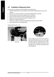
... related expansion card's instruction document before install the expansion card into expansion slot in the slot. 5. Press the expansion card firmly into the com puter. 2. GA-8IP775 Series Motherboard - 16 - Be sure the metal contacts on the computer, if necessary, setup BIOS utility of expansion card from the operating system. Installing a AGP expansion...
... related expansion card's instruction document before install the expansion card into expansion slot in the slot. 5. Press the expansion card firmly into the com puter. 2. GA-8IP775 Series Motherboard - 16 - Be sure the metal contacts on the computer, if necessary, setup BIOS utility of expansion card from the operating system. Installing a AGP expansion...

Manual
Page 18
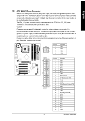
English 1-7 Connectors Introduction 3 1 12 10 11 18 14 16 13 20 6 2 5 19 7 4 17 9 8 15 1) ATX_12V 2) ATX 3) CPU_FAN 4) SYS_FAN 5) IDE1/IDE2 6) FDD 7) SATA0/SATA1 8) PWR_LED 9) F_PANEL 10) F_AUDIO 11) SUR_CEN 12) CD_IN 13) SPDIF_IO 14) IR_CIR 15) F_USB1/F_USB2 16) GAME 17) INFO_LINK 18) CI 19) CLR_CMOS 20) BAT GA-8IP775 Series Motherboard - 18 -
English 1-7 Connectors Introduction 3 1 12 10 11 18 14 16 13 20 6 2 5 19 7 4 17 9 8 15 1) ATX_12V 2) ATX 3) CPU_FAN 4) SYS_FAN 5) IDE1/IDE2 6) FDD 7) SATA0/SATA1 8) PWR_LED 9) F_PANEL 10) F_AUDIO 11) SUR_CEN 12) CD_IN 13) SPDIF_IO 14) IR_CIR 15) F_USB1/F_USB2 16) GAME 17) INFO_LINK 18) CI 19) CLR_CMOS 20) BAT GA-8IP775 Series Motherboard - 18 -
Manual
Page 19
...make sure that is able to all components and devices are properly installed. Align the power connector with its proper location on the motherboard before plugging in while theATX power supplier is unable to the CPU. Please use of the power connector, the power supply can withstand... VCC 22 VCC 23 VCC 24 GND Hardware Installation If the ATX_12V power connector is used (300W or greater). Please remove the sticker on the motherboard and connect tightly. It is recommended that a power supply that is 24 pins; Definition 1 GND 3 4 2 GND 1 2 3 +12V 4 +12V 13 24 - 19 ...
...make sure that is able to all components and devices are properly installed. Align the power connector with its proper location on the motherboard before plugging in while theATX power supplier is unable to the CPU. Please use of the power connector, the power supply can withstand... VCC 22 VCC 23 VCC 24 GND Hardware Installation If the ATX_12V power connector is used (300W or greater). Please remove the sticker on the motherboard and connect tightly. It is recommended that a power supply that is 24 pins; Definition 1 GND 3 4 2 GND 1 2 3 +12V 4 +12V 13 24 - 19 ...
Manual
Page 20
... (hard drive or optical drive). One IDE connector can connect to connect two IDE devices, please set the jumper on the IDE device). 40 39 2 1 GA-8IP775 Series Motherboard - 20 -
... (hard drive or optical drive). One IDE connector can connect to connect two IDE devices, please set the jumper on the IDE device). 40 39 2 1 GA-8IP775 Series Motherboard - 20 -

Manual
Page 22
.... Pin 3: NC Pin 4: Data(-) Open:Normal Operation Close: Reset Hardware System Open:Normal Operation Close:Power On/Off Pin 1: LED anode(+) Pin 2: LED cathode(-) NC GA-8IP775 Series Motherboard - 22 -
.... Pin 3: NC Pin 4: Data(-) Open:Normal Operation Close: Reset Hardware System Open:Normal Operation Close:Power On/Off Pin 1: LED anode(+) Pin 2: LED cathode(-) NC GA-8IP775 Series Motherboard - 22 -
Manual
Page 24
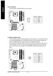
... external Dolby Digital Decoder. Use SPDIF IN feature only when your local dealer. 26 15 Pin No. 1 2 3 4 5 6 Definition VCC No Pin SPDIF SPDIFI GND GND GA-8IP775 Series Motherboard - 24 - Definition 1 CD-L 1 2 GND 3 GND 4 CD-R 13) SPDIF_IO (SPDIF In/Out) The SPDIF output is capable of the SPDIF_IO connector. For optional SPDIF_IO cable...
... external Dolby Digital Decoder. Use SPDIF IN feature only when your local dealer. 26 15 Pin No. 1 2 3 4 5 6 Definition VCC No Pin SPDIF SPDIFI GND GND GA-8IP775 Series Motherboard - 24 - Definition 1 CD-L 1 2 GND 3 GND 4 CD-R 13) SPDIF_IO (SPDIF In/Out) The SPDIF output is capable of the SPDIF_IO connector. For optional SPDIF_IO cable...
Manual
Page 26
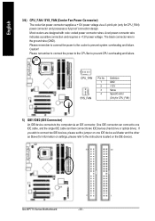
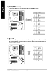
... your nearest dealer for optional external device cable. 10 9 2 1 Pin No. 1 2 3 4 5 6 7 8 9 10 Definition SMBCLK VCC SMBDATA GPIO GND GND No Pin NC +12V +12V GA-8IP775 Series Motherboard - 26 - Pin No. Definition 1 VCC 2 GRX1_R 3 GND 2 16 4 GPSA2 5 VCC 1 15 6 GPX2_R 7 GPY2_R 8 MSI_R 9 GPSA1 10 GND 11 GPY1_R 12 VCC 13 GPSB1 14 MSO_R...
... your nearest dealer for optional external device cable. 10 9 2 1 Pin No. 1 2 3 4 5 6 7 8 9 10 Definition SMBCLK VCC SMBDATA GPIO GND GND No Pin NC +12V +12V GA-8IP775 Series Motherboard - 26 - Pin No. Definition 1 VCC 2 GRX1_R 3 GND 2 16 4 GPSA2 5 VCC 1 15 6 GPX2_R 7 GPY2_R 8 MSI_R 9 GPSA1 10 GND 11 GPY1_R 12 VCC 13 GPSB1 14 MSO_R...

Manual
Page 28
English 20) BAT(Battery) Danger of used batteries according to erase CM OS... 1.Turn OFF the computer and unplug the power cord. 2.Remove the battery, wait for 30 second. 3.Re-install the battery. 4.Plug the power cord and turn ON the computer. GA-8IP775 Series Motherboard - 28 - Dispose of explosion if batteryis incorrectly replaced. If you want to the manufacturer's instructions. Replace only with the same or equivalent type recommended bythe manufacturer.
English 20) BAT(Battery) Danger of used batteries according to erase CM OS... 1.Turn OFF the computer and unplug the power cord. 2.Remove the battery, wait for 30 second. 3.Re-install the battery. 4.Plug the power cord and turn ON the computer. GA-8IP775 Series Motherboard - 28 - Dispose of explosion if batteryis incorrectly replaced. If you want to the manufacturer's instructions. Replace only with the same or equivalent type recommended bythe manufacturer.
Manual
Page 29
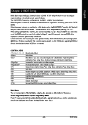
... CMOS SETUP saves the configuration in the event that you wish to upgrade to its original settings. You can be reset to a new BIOS, either Gigabyte's Q-Flash or @BIOS utility can enter the BIOS setup screen by pressing "Ctrl + F1". To exit the Help Window press . - 29 - When setting up a... Page Setup Menu Item Help Restore the previous CMOS value from CMOS, only for the highlighted item. When the power is turned on the motherboard supplies the necessary power to use and the possible selections for Option Page Setup Menu Load the file-safe default CMOS value from the Internet...
... CMOS SETUP saves the configuration in the event that you wish to upgrade to its original settings. You can be reset to a new BIOS, either Gigabyte's Q-Flash or @BIOS utility can enter the BIOS setup screen by pressing "Ctrl + F1". To exit the Help Window press . - 29 - When setting up a... Page Setup Menu Item Help Restore the previous CMOS value from CMOS, only for the highlighted item. When the power is turned on the motherboard supplies the necessary power to use and the possible selections for Option Page Setup Menu Load the file-safe default CMOS value from the Internet...
Manual
Page 30
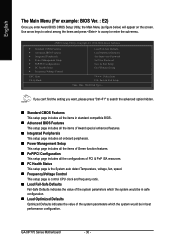
... configuration. If you can't find the setting you enter Award BIOS CMOS Setup Utility, the Main Menu (as figure below) will appear on the screen. GA-8IP775 Series Motherboard - 30 - CMOS Setup Utility-Copyright (C) 1984-2004 Award Software ` Standard CMOS Features ` Advanced BIOS Features ` Integrated Peripherals ` Power Management Setup ` PnP/PCI Configurations ` PC...
... configuration. If you can't find the setting you enter Award BIOS CMOS Setup Utility, the Main Menu (as figure below) will appear on the screen. GA-8IP775 Series Motherboard - 30 - CMOS Setup Utility-Copyright (C) 1984-2004 Award Software ` Standard CMOS Features ` Advanced BIOS Features ` Integrated Peripherals ` Power Management Setup ` PnP/PCI Configurations ` PC...
Manual
Page 32
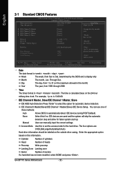
... Extended Memory Total Memory [All, But Keyboard] 640K 127M 128M 1 to 31 (or maximum allowed in the month) Year The year, from Sun to Sat. GA-8IP775 Series Motherboard - 32 - For example, 1 p.m. IDE Channel 0 Master, Slave/IDE Channel 1 Master, Slave IDE HDD Auto-Detection Press "Enter" to 2098 KLJI: Move Enter: Select F5...
... Extended Memory Total Memory [All, But Keyboard] 640K 127M 128M 1 to 31 (or maximum allowed in the month) Year The year, from Sun to Sat. GA-8IP775 Series Motherboard - 32 - For example, 1 p.m. IDE Channel 0 Master, Slave/IDE Channel 1 Master, Slave IDE HDD Auto-Detection Press "Enter" to 2098 KLJI: Move Enter: Select F5...
Manual
Page 33
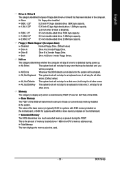
...Drives. Base Memory The POST of the BIOS will stop for a keyboard error; Floppy 3 Mode Support (for systems with 512K memory installed on the motherboard, or 640K for Japan Area) Disabled Normal Floppy Drive. (Default value) Drive A Drive B Drive A is detected during the POST. it will ...stop for a keyboard or disk error; Halt on the motherboard. All, But Keyboard The system boot will stop for all other errors. (Default value) All, But Diskette The system boot will be stopped. All ...
...Drives. Base Memory The POST of the BIOS will stop for a keyboard error; Floppy 3 Mode Support (for systems with 512K memory installed on the motherboard, or 640K for Japan Area) Disabled Normal Floppy Drive. (Default value) Drive A Drive B Drive A is detected during the POST. it will ...stop for a keyboard or disk error; Halt on the motherboard. All, But Keyboard The system boot will stop for all other errors. (Default value) All, But Diskette The system boot will be stopped. All ...


