
Manual
Page 2
...If you may prepare only one hard drive. (b) An empty formatted floppy disk. (c) Windows XP/2000 setup disk. (d) Driver CD for your motherboard. (1) Installing SATA hard drive(s) in your computer Attach one end of the SATA signal cable to the rear of the SATA connector to available SATA... more than one SATA controller on your system. (2) Configure SATA controller mode and boot sequence in BIOS Setup. (3)* Configure RAID set in your motherboard, you do not want to create RAID with identical model and capacity). Before you begin Please prepare: (a) Two SATA hard drives (to ensure ...
...If you may prepare only one hard drive. (b) An empty formatted floppy disk. (c) Windows XP/2000 setup disk. (d) Driver CD for your motherboard. (1) Installing SATA hard drive(s) in your computer Attach one end of the SATA signal cable to the rear of the SATA connector to available SATA... more than one SATA controller on your system. (2) Configure SATA controller mode and boot sequence in BIOS Setup. (3)* Configure RAID set in your motherboard, you do not want to create RAID with identical model and capacity). Before you begin Please prepare: (a) Two SATA hard drives (to ensure ...
Manual
Page 3
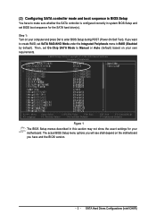
... show the exact settings for the SATA hard drive(s). Step 1: Turn on your computer and press Del to Manual or Auto (default) based on the motherboard you want to create RAID, set BIOS boot sequence for your own requirements. If you have to RAID (Disabled by default). The actual BIOS Setup...
... show the exact settings for the SATA hard drive(s). Step 1: Turn on your computer and press Del to Manual or Auto (default) based on the motherboard you want to create RAID, set BIOS boot sequence for your own requirements. If you have to RAID (Disabled by default). The actual BIOS Setup...
Manual
Page 9
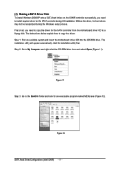
... CD into the CD-ROM drive. Figure 11 Step 3: Go to the BootDrv folder and look for the SATA controller from the motherboard driver CD to a floppy disk. The instructions below explain how to My Computer and right-click the CD-ROM drive icon and select Open (Figure ...
... CD into the CD-ROM drive. Figure 11 Step 3: Go to the BootDrv folder and look for the SATA controller from the motherboard driver CD to a floppy disk. The instructions below explain how to My Computer and right-click the CD-ROM drive icon and select Open (Figure ...

Manual
Page 10
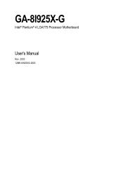
Step 6: Press 0 to the floppy disk. SATA Hard Drives Configurations (Intel ICH6R) Figure 14 - 10 - Then it will appear. An MS-DOS prompt screen similar to select 1)Intel Application Accelerator 4.0. Figure 13 Step 5: Insert an empty floppy disk and press 1 to Figure 13 below will take about one minute to copy the SATA driver from the motherboard driver CD to exit when the procedure is complete (Figure 14). You have copied the SATA driver sucessfully. Step 4: Double-click MENU.exe.
Step 6: Press 0 to the floppy disk. SATA Hard Drives Configurations (Intel ICH6R) Figure 14 - 10 - Then it will appear. An MS-DOS prompt screen similar to select 1)Intel Application Accelerator 4.0. Figure 13 Step 5: Insert an empty floppy disk and press 1 to Figure 13 below will take about one minute to copy the SATA driver from the motherboard driver CD to exit when the procedure is complete (Figure 14). You have copied the SATA driver sucessfully. Step 4: Double-click MENU.exe.

Manual
Page 12
... the driver in about one or some file(s) cannot be found, please check the floppy disk or copy the correct SATA driver again from the motherboard driver CD. The driver installation will be finished in the floppy disk, a controller menu similar to Figure 20 below appears, press ENTER to select Intel...
... the driver in about one or some file(s) cannot be found, please check the floppy disk or copy the correct SATA driver again from the motherboard driver CD. The driver installation will be finished in the floppy disk, a controller menu similar to Figure 20 below appears, press ENTER to select Intel...
Manual
Page 1
GA-8I925X-G Intel® Pentium® 4 LGA775 Processor Motherboard User's Manual Rev. 2003 12ME-8I925XG-2003
GA-8I925X-G Intel® Pentium® 4 LGA775 Processor Motherboard User's Manual Rev. 2003 12ME-8I925XG-2003
Manual
Page 2
Motherboard GA-8I925X-G Jul. 2, 2004 Motherboard GA-8I925X-G Jul. 2, 2004
Motherboard GA-8I925X-G Jul. 2, 2004 Motherboard GA-8I925X-G Jul. 2, 2004
Manual
Page 4
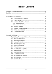
Table of Contents GA-8I925X-G Motherboard Layout 6 Block Diagram ...7 Chapter 1 Hardware Installation 9 1-1 Considerations Prior to Installation 9 1-2 Feature Summary 10 1-3 Installation of the CPU and Heatsink 12 1-3-1 Installation of the CPU 12 1-3-2 ...
Table of Contents GA-8I925X-G Motherboard Layout 6 Block Diagram ...7 Chapter 1 Hardware Installation 9 1-1 Considerations Prior to Installation 9 1-2 Feature Summary 10 1-3 Installation of the CPU and Heatsink 12 1-3-1 Installation of the CPU 12 1-3-2 ...
Manual
Page 6
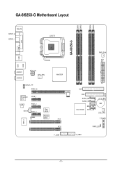
GA-8I925X-G Motherboard Layout DDRII1 DDRII2 DDRII4 DDRII5 KB_MS SPDIF_O SPDIF_I LGA775 GA-8I925X-G COM LPT USB USB LAN2 IT8712 AUDIO1 AUDIO2 ATX_12V CPU_FAN AZALIA_FP PCIE_16 Broadcom 5751 CODEC PCIE_1 PCIE_2 CD_IN PCIE_3 IR Main BIOS Backup BIOS Intel 925X PCI1 PCI2 F_USB1 PWR_FAN ATX IDE FDD SATA3_SB SATA2_SB Intel ICH6R SATA1_SB SATA0_SB BAT SYS_FAN F_PANEL PWR_LED F_USB2 CLR_CMOS - 6 -
GA-8I925X-G Motherboard Layout DDRII1 DDRII2 DDRII4 DDRII5 KB_MS SPDIF_O SPDIF_I LGA775 GA-8I925X-G COM LPT USB USB LAN2 IT8712 AUDIO1 AUDIO2 ATX_12V CPU_FAN AZALIA_FP PCIE_16 Broadcom 5751 CODEC PCIE_1 PCIE_2 CD_IN PCIE_3 IR Main BIOS Backup BIOS Intel 925X PCI1 PCI2 F_USB1 PWR_FAN ATX IDE FDD SATA3_SB SATA2_SB Intel ICH6R SATA1_SB SATA0_SB BAT SYS_FAN F_PANEL PWR_LED F_USB2 CLR_CMOS - 6 -
Manual
Page 7
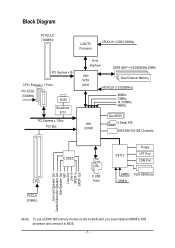
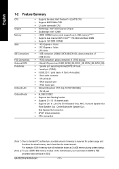
... Center/Subwoofer Speaker Out Side Speaker Out MIC Line-Out Line-In SPDIF In SPDIF Out (Note) To use a DDRII 600 memory module on the motherboard, you must install an 800MHz FSB processor and overclock in BIOS. - 7 -
... Center/Subwoofer Speaker Out Side Speaker Out MIC Line-Out Line-In SPDIF In SPDIF Out (Note) To use a DDRII 600 memory module on the motherboard, you must install an 800MHz FSB processor and overclock in BIOS. - 7 -
Manual
Page 9
... components (CPU, RAM). 4. Hardware Installation Product determined to the user. 8. Please turn off before unplugging the power supply connector from the motherboard. Damage as physical harm to be an unofficial Gigabyte product. - 9 - Turning on an uneven surface. 7. Before using the product, please verify that you are connected. 4. Instances of violating the conditions...
... components (CPU, RAM). 4. Hardware Installation Product determined to the user. 8. Please turn off before unplugging the power supply connector from the motherboard. Damage as physical harm to be an unofficial Gigabyte product. - 9 - Turning on an uneven surface. 7. Before using the product, please verify that you are connected. 4. Instances of violating the conditions...
Manual
Page 10
... be shown as 3.xxGB memory during system startup. (Note 2) To use a DDRII 600 memory module on the motherboard, you must install an 800MHz FSB processor and overclock in BIOS. Center/Subwoofer Speaker Out ; GA-8I925X-G Motherboard - 10 - English 1-2 Feature Summary CPU Chipset Memory Slots IDE Connections FDD Connections Onboard SATA Peripherals Onboard LAN Onboard...
... be shown as 3.xxGB memory during system startup. (Note 2) To use a DDRII 600 memory module on the motherboard, you must install an 800MHz FSB processor and overclock in BIOS. Center/Subwoofer Speaker Out ; GA-8I925X-G Motherboard - 10 - English 1-2 Feature Summary CPU Chipset Memory Slots IDE Connections FDD Connections Onboard SATA Peripherals Onboard LAN Onboard...
Manual
Page 12
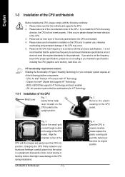
... for your hardware specifications including the CPU, graphics card, memory, hard drive, etc. It is installed on the CPU socket to the CPU during installation.) GA-8I925X-G Motherboard - 12 - BIOS: A BIOS that might cause damage to the upright position. Please make sure that supports HT Technology - Fig. 3 Notice the small gold colored triangle.... If you install the CPU in a straight and downwards motion. Please add an even layer of the CPU. Chipset: An Intel® Chipset that the motherboard supports the CPU. 2.
... for your hardware specifications including the CPU, graphics card, memory, hard drive, etc. It is installed on the CPU socket to the CPU during installation.) GA-8I925X-G Motherboard - 12 - BIOS: A BIOS that might cause damage to the upright position. Please make sure that supports HT Technology - Fig. 3 Notice the small gold colored triangle.... If you install the CPU in a straight and downwards motion. Please add an even layer of the CPU. Chipset: An Intel® Chipset that the motherboard supports the CPU. 2.
Manual
Page 13
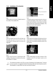
... inwards before installation. (This instruction is to the heatsink installation section of the user manual) Fig. 5 Please check the back of motherboard after installing. Fig. 6 Finally, please attach the power connector of the heatsink to the CPU as the picture, the installation is suggested... heat sink paste be used for detailed installation instructions, please refer to install.) Please note the direction of arrow sign on the motherboard. Hardware Installation To prevent such an occurrence, it is complete. English 1-3-2 Installation of the Heatsink Male Push Pin The top of...
... inwards before installation. (This instruction is to the heatsink installation section of the user manual) Fig. 5 Please check the back of motherboard after installing. Fig. 6 Finally, please attach the power connector of the heatsink to the CPU as the picture, the installation is suggested... heat sink paste be used for detailed installation instructions, please refer to install.) Please note the direction of arrow sign on the motherboard. Hardware Installation To prevent such an occurrence, it is complete. English 1-3-2 Installation of the Heatsink Male Push Pin The top of...
Manual
Page 14
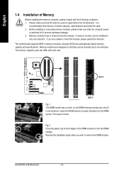
...foolproof insertion design. Insert the DIMM memory module vertically into the DIMM socket. GA-8I925X-G Motherboard - 14 - Please make sure that they can be installed in only one direction. The motherboard supports DDR II memory modules, whereby BIOS will automatically detect memory capacity and specifications... switch the direction. Reverse the installation steps when you are designed so that the computer power is supported by the motherboard. It is recommended that the memory used can only fit in one direction. English 1-4 Installation of similar capacity, ...
...foolproof insertion design. Insert the DIMM memory module vertically into the DIMM socket. GA-8I925X-G Motherboard - 14 - Please make sure that they can be installed in only one direction. The motherboard supports DDR II memory modules, whereby BIOS will automatically detect memory capacity and specifications... switch the direction. Reverse the installation steps when you are designed so that the computer power is supported by the motherboard. It is recommended that the memory used can only fit in one direction. English 1-4 Installation of similar capacity, ...
Manual
Page 16
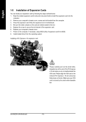
... from the computer. 3. Install related driver from BIOS. 8. Make sure your VGA card is locked by following the steps outlined below: 1. GA-8I925X-G Motherboard - 16 - Press the expansion card firmly into the computer. 2. Replace the screw to the onboard PCI Express x 16 slot and press firmly... down on the card are indeed seated in motherboard. 4. Remove your computer's chassis cover. 7. Installing a PCI Express x 16 expansion card: Please carefully pull out the small whitedrawable bar ...
... from the computer. 3. Install related driver from BIOS. 8. Make sure your VGA card is locked by following the steps outlined below: 1. GA-8I925X-G Motherboard - 16 - Press the expansion card firmly into the computer. 2. Replace the screw to the onboard PCI Express x 16 slot and press firmly... down on the card are indeed seated in motherboard. 4. Remove your computer's chassis cover. 7. Installing a PCI Express x 16 expansion card: Please carefully pull out the small whitedrawable bar ...
Manual
Page 18
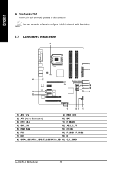
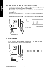
You can use audio software to this connector. English Side Speaker Out Connect the side surround speakers to configure 2-/4-/6-/8-channel audio functioning. 1-7 Connectors Introduction 13 5 2 12 7 6 16 10 13 4 15 14 8 9 11 1) ATX_12V 9) PWR_LED 2) ATX (Power Connector) 10) BAT 3) CPU_FAN 11) F_PANEL 4) SYS_FAN 12) AZALIA_FP 5) PWR_FAN 13) CD_IN 6) FDD 14) F_USB1 / F_USB2 7) IDE 15) IR 8) SATA0_SB/SATA1_SB/SATA2_SB/SATA3_SB 16) CLR_CMOS GA-8I925X-G Motherboard - 18 -
You can use audio software to this connector. English Side Speaker Out Connect the side surround speakers to configure 2-/4-/6-/8-channel audio functioning. 1-7 Connectors Introduction 13 5 2 12 7 6 16 10 13 4 15 14 8 9 11 1) ATX_12V 9) PWR_LED 2) ATX (Power Connector) 10) BAT 3) CPU_FAN 11) F_PANEL 4) SYS_FAN 12) AZALIA_FP 5) PWR_FAN 13) CD_IN 6) FDD 14) F_USB1 / F_USB2 7) IDE 15) IR 8) SATA0_SB/SATA1_SB/SATA2_SB/SATA3_SB 16) CLR_CMOS GA-8I925X-G Motherboard - 18 -
Manual
Page 19
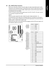
Before connecting the power connector, please make sure that all the components on the motherboard. Caution! Please remove the sticker on the motherboard and connect tightly. Hardware Installation Otherwise, please do not remove it. 42 31 Pin No. 1 2 3 4 Definition GND GND +12V +12V Pin No....If a power supply is used (300W or greater). It is unable to start . Align the power connector with its proper location on the motherboard before plugging in while the ATX power supplier is not connected, the system will not start . English 1/2) ATX_12V/ATX (Power Connector) With...
Before connecting the power connector, please make sure that all the components on the motherboard. Caution! Please remove the sticker on the motherboard and connect tightly. Hardware Installation Otherwise, please do not remove it. 42 31 Pin No. 1 2 3 4 Definition GND GND +12V +12V Pin No....If a power supply is used (300W or greater). It is unable to start . Align the power connector with its proper location on the motherboard before plugging in while the ATX power supplier is not connected, the system will not start . English 1/2) ATX_12V/ATX (Power Connector) With...
Manual
Page 20
... end of FDD drives supported are designed with color-coded power connector wires. The types of the cable connects to the pin1 position. 2 34 1 33 GA-8I925X-G Motherboard - 20 - Please remember to connect the power to the CPU fan to prevent CPU overheating and failure. 1 CPU_FAN Pin No. 1 2 3 4 1 SYS_FAN / PWR_FAN Definition GND +12V...
... end of FDD drives supported are designed with color-coded power connector wires. The types of the cable connects to the pin1 position. 2 34 1 33 GA-8I925X-G Motherboard - 20 - Please remember to connect the power to the CPU fan to prevent CPU overheating and failure. 1 CPU_FAN Pin No. 1 2 3 4 1 SYS_FAN / PWR_FAN Definition GND +12V...
Manual
Page 22
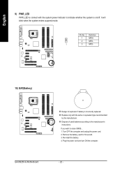
Pin No. Definition 1 MPD+ 2 MPD- 1 3 MPD- 10) BAT(Battery) GA-8I925X-G Motherboard Danger of used batteries according to the manufacturer's instructions. If you want to indicate whether the system is incorrectly replaced. Remove the battery, wait for ...
Pin No. Definition 1 MPD+ 2 MPD- 1 3 MPD- 10) BAT(Battery) GA-8I925X-G Motherboard Danger of used batteries according to the manufacturer's instructions. If you want to indicate whether the system is incorrectly replaced. Remove the battery, wait for ...


