
User Manual
Page 11
... Motherboard CPU Chipset Clock Generator Memory I/O Control Slots On-Board IDE On-Board Peripherals Hardware Monitor (Optional) Ÿ 30.6 cm x 22 cm ATX size form factor, 4 layers PCB. Ÿ 7VX series includes 7VX, 7VX-1 Ÿ AMD Athlon (K7) Slot A Processor Ÿ 512 KB 2nd cache in CPU Module Ÿ Supports 500MHz ~ 1GHz and faster Apollo KX133 ,consisting of: Ÿ VIA8371 Memory/AGP/PCI Controller(PAC) Ÿ VT82C686A PCI Super-I/O Integrated Peripheral Controller (PSIPC) Ÿ Supports 100~143MHz Ÿ 3 168-pin...
... Motherboard CPU Chipset Clock Generator Memory I/O Control Slots On-Board IDE On-Board Peripherals Hardware Monitor (Optional) Ÿ 30.6 cm x 22 cm ATX size form factor, 4 layers PCB. Ÿ 7VX series includes 7VX, 7VX-1 Ÿ AMD Athlon (K7) Slot A Processor Ÿ 512 KB 2nd cache in CPU Module Ÿ Supports 500MHz ~ 1GHz and faster Apollo KX133 ,consisting of: Ÿ VIA8371 Memory/AGP/PCI Controller(PAC) Ÿ VT82C686A PCI Super-I/O Integrated Peripheral Controller (PSIPC) Ÿ Supports 100~143MHz Ÿ 3 168-pin...

User Manual
Page 13
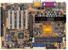
FDD1 JP4 7VX Series Motherboard 7VX Series Motherboard Layout PS/2 J10 USB JP5 J5 SW4 ATX POWER COM1 CPU LPT VT8371 COM2 IDE1 IDE2 PCI 1 J15 J14 PCI 2 J11 AC97 PCI 3 JP14 PCI 4 CT5880 PCI 5 JP7 AMR 1 I SA1 AGP 1 JP9 JP8 7VX VT82C 686A MAIN BIOS BACK BIOS J6 J3 J4 JP1 BAT1 LED1 JP3 JP2 USB2 JP6 J1 J2 5
FDD1 JP4 7VX Series Motherboard 7VX Series Motherboard Layout PS/2 J10 USB JP5 J5 SW4 ATX POWER COM1 CPU LPT VT8371 COM2 IDE1 IDE2 PCI 1 J15 J14 PCI 2 J11 AC97 PCI 3 JP14 PCI 4 CT5880 PCI 5 JP7 AMR 1 I SA1 AGP 1 JP9 JP8 7VX VT82C 686A MAIN BIOS BACK BIOS J6 J3 J4 JP1 BAT1 LED1 JP3 JP2 USB2 JP6 J1 J2 5

User Manual
Page 14
7VX Motherboard Layout $ Page Index for CPU Speed Setup / Connectors / Panel and Jumper Page Definition CPU Speed Setup P.7 Connectors P.8 Game & Audio Port P.8 COM 1 / COM 2 / LPT Port P.8 USB Connector P.9 PS/2 Keyboard & PS/2 Mouse Connector P.9 J10 Power Fan P.10 J5 CPU Fan P.10 J6 System Fan P.11 ATX Power P.11 Floppy Port P.12 IDE 1(Primary) / IDE 2(Secondary) Prot P.12 USB2 (USB Port) P.13 IR (Optional) P.13 JP3 (STR LED Connector & LED1: DIMM LED) P.14 J3 (Modem Wake Up) P.14 J4 (LAN Wake Up) P.15 J15 (TEL) P.15 J11 (AUX_IN) P.16 J14 (CD Audio...
7VX Motherboard Layout $ Page Index for CPU Speed Setup / Connectors / Panel and Jumper Page Definition CPU Speed Setup P.7 Connectors P.8 Game & Audio Port P.8 COM 1 / COM 2 / LPT Port P.8 USB Connector P.9 PS/2 Keyboard & PS/2 Mouse Connector P.9 J10 Power Fan P.10 J5 CPU Fan P.10 J6 System Fan P.11 ATX Power P.11 Floppy Port P.12 IDE 1(Primary) / IDE 2(Secondary) Prot P.12 USB2 (USB Port) P.13 IR (Optional) P.13 JP3 (STR LED Connector & LED1: DIMM LED) P.14 J3 (Modem Wake Up) P.14 J4 (LAN Wake Up) P.15 J15 (TEL) P.15 J11 (AUX_IN) P.16 J14 (CD Audio...

User Manual
Page 25
...7VX Series Motherboard Panel And Jumper Definition J2 : For 2X11 PINs Jumper GN HD 1 S P K 1 P−P−P+ RE 1 PW GD 1 GN (Green Switch) GD (Green LED) HD (IDE Hard Disk Active LED) SPK (Speaker Connector) RE (Reset Switch) P+P−P−(Power LED) PW (Soft Power Connector) Open: Normal Operation Close: Entering Green Mode Pin 1: LED anode(+) Pin 2: LED cathode(−) Pin 1: LED anode(+) Pin 2: LED cathode(−) Pin 1: VCC(+) Pin 2- Pin 3: NC Pin 4: Data(−) Open: Normal Operation Close: Reset Hardware System Pin 1: LED anode(+) Pin 2: LED cathode(−) Pin 3: LED...
...7VX Series Motherboard Panel And Jumper Definition J2 : For 2X11 PINs Jumper GN HD 1 S P K 1 P−P−P+ RE 1 PW GD 1 GN (Green Switch) GD (Green LED) HD (IDE Hard Disk Active LED) SPK (Speaker Connector) RE (Reset Switch) P+P−P−(Power LED) PW (Soft Power Connector) Open: Normal Operation Close: Entering Green Mode Pin 1: LED anode(+) Pin 2: LED cathode(−) Pin 1: LED anode(+) Pin 2: LED cathode(−) Pin 1: VCC(+) Pin 2- Pin 3: NC Pin 4: Data(−) Open: Normal Operation Close: Reset Hardware System Pin 1: LED anode(+) Pin 2: LED cathode(−) Pin 3: LED...

User Manual
Page 26
... SETUP" option.) 18 You will enter BIOS Setup. Select the item "POWER MANAGEMENT SETUP", then select "USB Dev Wakeup From S3: Enabled". Definition 1-2 close FP USB Wake Up 2-3 close Normal (Default) (If you want to use "USB Dev Wakeup From S3" function, you update new BIOS or new device JP6 : Front Panel USB Device Wake up From S3" enabled, and the jumper "JP6" enabled). *(Power on the computer and as soon as memory counting starts, press . JP2 : BIOS...
... SETUP" option.) 18 You will enter BIOS Setup. Select the item "POWER MANAGEMENT SETUP", then select "USB Dev Wakeup From S3: Enabled". Definition 1-2 close FP USB Wake Up 2-3 close Normal (Default) (If you want to use "USB Dev Wakeup From S3" function, you update new BIOS or new device JP6 : Front Panel USB Device Wake up From S3" enabled, and the jumper "JP6" enabled). *(Power on the computer and as soon as memory counting starts, press . JP2 : BIOS...

User Manual
Page 30
... Hardware & Software configuration will result in different benchmark testing results.) • CPU AMD AthlonTM 800MHz processor • DRAM (128x1) MB SDRAM (MOSEL 9928PR V54C365804VCT7) • CACHE SIZE • DISPLAY • STORAGE • O.S. • DRIVER 512 KB included in CPU GA-660 PLUS 32 (32MB) Onboard IDE (Quantum KA13600AT) Windows NT™ 4.0 SP6 Display Driver at 1024 x 768 x 64k colors x 75Hz. • BUS MASTER 4 IN 1 Driver (Ver. 4.20) Processor Winbench99 CPU mark...
... Hardware & Software configuration will result in different benchmark testing results.) • CPU AMD AthlonTM 800MHz processor • DRAM (128x1) MB SDRAM (MOSEL 9928PR V54C365804VCT7) • CACHE SIZE • DISPLAY • STORAGE • O.S. • DRIVER 512 KB included in CPU GA-660 PLUS 32 (32MB) Onboard IDE (Quantum KA13600AT) Windows NT™ 4.0 SP6 Display Driver at 1024 x 768 x 64k colors x 75Hz. • BUS MASTER 4 IN 1 Driver (Ver. 4.20) Processor Winbench99 CPU mark...

User Manual
Page 33
Definition ON STR Enabled OFF STR Disabled Step 3: Power on the computer and as soon as memory counting starts, press . Remember to use the STR function. 25 Congratulation! You have completed the installation and now can use STR Function, please set jumper JP4 (ON) 1 Pin No. You will enter BIOS Setup. Select the item "POWER MANAGEMENT SETUP", then select "ACPI Sleep State: S3 /STR". 7VX Series Motherboard Step 2: (If you want to save the settings by pressing "ESC" and choose the "SAVE & EXIT SETUP" option.
Definition ON STR Enabled OFF STR Disabled Step 3: Power on the computer and as soon as memory counting starts, press . Remember to use the STR function. 25 Congratulation! You have completed the installation and now can use STR Function, please set jumper JP4 (ON) 1 Pin No. You will enter BIOS Setup. Select the item "POWER MANAGEMENT SETUP", then select "ACPI Sleep State: S3 /STR". 7VX Series Motherboard Step 2: (If you want to save the settings by pressing "ESC" and choose the "SAVE & EXIT SETUP" option.

User Manual
Page 36
Use the "Wake On LAN"function. 5. There are five ways to RAM Installation C. Suspend to "wake up"the system: 1. Use the "Resume by Alarm"function. 3. Step 4: Restart your computer to recover from the STR sleep mode? Use the "USB Device Wake Up"function. 28 A.4 How to complete setup. Use the "Modem Ring On"function. 4. Now when you want to enter STR sleep mode, just momentarily press the "Power on"button.. Press the "Power On"button. 2. Select the "Advanced"tab and "Standby"mode in Power Buttons.
Use the "Wake On LAN"function. 5. There are five ways to RAM Installation C. Suspend to "wake up"the system: 1. Use the "Resume by Alarm"function. 3. Step 4: Restart your computer to recover from the STR sleep mode? Use the "USB Device Wake Up"function. 28 A.4 How to complete setup. Use the "Modem Ring On"function. 4. Now when you want to enter STR sleep mode, just momentarily press the "Power on"button.. Press the "Power On"button. 2. Select the "Advanced"tab and "Standby"mode in Power Buttons.

User Manual
Page 38
... are two system BIOS (ROM) on the Main BIOS. Boot Screen American Megatrends AMIBIOS (C) 1999 American Megatrends Inc., xxx xxx Check System Health ok , AMD-Athlon™-750MHz Check NVRAM... How to enter Dual BIOS Utility. a. Wait... Dual BIOS means that your BIOS. Under the normal circumstances, the system works on the motherboard, one is the Main BIOS and the other is Backup BIOS. Press F1 to use Dual BIOS? Press F1...
... are two system BIOS (ROM) on the Main BIOS. Boot Screen American Megatrends AMIBIOS (C) 1999 American Megatrends Inc., xxx xxx Check System Health ok , AMD-Athlon™-750MHz Check NVRAM... How to enter Dual BIOS Utility. a. Wait... Dual BIOS means that your BIOS. Under the normal circumstances, the system works on the motherboard, one is the Main BIOS and the other is Backup BIOS. Press F1 to use Dual BIOS? Press F1...

User Manual
Page 39
... BIOS automatically. 7VX Series Motherboard b. AMI Dual BIOS Flash ROM Programming Utility AMI Dual BIOS Flash ROM Programming Utility V1.01 Boot From Main BIOS Main ROM Type SST 39SF020 Backup ROM Type SST 39SF020 Wide Range Protection Disable Boot From Main BIOS Auto Recovery Enable Halt On Error Disable Copy Main ROM Data to Backup Load Default Settings Save Settings to request restart of the system after the power is on, and that the Wide Range Protection is loaded and after the user make any failure (ex. Update ESCD failure, checksum error or reset...
... BIOS automatically. 7VX Series Motherboard b. AMI Dual BIOS Flash ROM Programming Utility AMI Dual BIOS Flash ROM Programming Utility V1.01 Boot From Main BIOS Main ROM Type SST 39SF020 Backup ROM Type SST 39SF020 Wide Range Protection Disable Boot From Main BIOS Auto Recovery Enable Halt On Error Disable Copy Main ROM Data to Backup Load Default Settings Save Settings to request restart of the system after the power is on, and that the Wide Range Protection is loaded and after the user make any failure (ex. Update ESCD failure, checksum error or reset...

User Manual
Page 40
... the Main BIOS. (This auto recovery utility is set to Suspend to RAM, the Auto Recovery will be changed by system automatically and can set by user.) 32 Auto Recovery : Enabled(Default), Disabled When one of the Main BIOS or Backup BIOS occurs checksum failure, the working BIOS will show Copy Main ROM Data to Backup Backup message: Are you want to enter the BIOS setting, please press "Del" key when the boot screen appears.) Halt On Error : Disable(Default), Enable If the BIOS occurs a checksum error...
... the Main BIOS. (This auto recovery utility is set to Suspend to RAM, the Auto Recovery will be changed by system automatically and can set by user.) 32 Auto Recovery : Enabled(Default), Disabled When one of the Main BIOS or Backup BIOS occurs checksum failure, the working BIOS will show Copy Main ROM Data to Backup Backup message: Are you want to enter the BIOS setting, please press "Del" key when the boot screen appears.) Halt On Error : Disable(Default), Enable If the BIOS occurs a checksum error...

User Manual
Page 42
... if a user resets the system, or if the power button is limited according to the user. Dual BIOS Introduction I. If a user changes peripherals often, there is a slight chance of this technology is completely transparent to electronic characteristics. Your PC will be unstable or even not boot normally. 2. The modern PC utilizes the Plug and Play BIOS, and is a patented technology from Giga-Byte Technology. This new technology will...
... if a user resets the system, or if the power button is limited according to the user. Dual BIOS Introduction I. If a user changes peripherals often, there is a slight chance of this technology is completely transparent to electronic characteristics. Your PC will be unstable or even not boot normally. 2. The modern PC utilizes the Plug and Play BIOS, and is a patented technology from Giga-Byte Technology. This new technology will...

User Manual
Page 56
... safe configuration. • Load Setup Defaults Setup Defaults indicates the value of the system parameters which the system would be in best performance configuration. • Integrated Peripherals This setup page includes all onboard peripherals. • Hardware Monitor Setup This setup page is the System auto detect Temperature, voltage , fan, speed. • Supervisor Password Change, set , or disable password. It allows you to limit access to the system and Setup, or just to the system. • IDE HDD auto...
... safe configuration. • Load Setup Defaults Setup Defaults indicates the value of the system parameters which the system would be in best performance configuration. • Integrated Peripherals This setup page includes all onboard peripherals. • Hardware Monitor Setup This setup page is the System auto detect Temperature, voltage , fan, speed. • Supervisor Password Change, set , or disable password. It allows you to limit access to the system and Setup, or just to the system. • IDE HDD auto...

User Manual
Page 60
.... 720K, 3.5 in. 1.44M, 3.5 in. 2.88M, 3.5 in . No floppy drive installed. 5.25 inch PC-type standard drive; 360K byte capacity. 5.25 inch AT-type high-density drive; 1.2M byte capacity (3.5 inch when 3 Mode is user-definable; There are two types: auto type, and manual type. For example, 1 p.m. The hard disk will not work properly if you select User Type, related information will automatically detect HDD type. SECTORS Number of cylinders. The time is...
.... 720K, 3.5 in. 1.44M, 3.5 in. 2.88M, 3.5 in . No floppy drive installed. 5.25 inch PC-type standard drive; 360K byte capacity. 5.25 inch AT-type high-density drive; 1.2M byte capacity (3.5 inch when 3 Mode is user-definable; There are two types: auto type, and manual type. For example, 1 p.m. The hard disk will not work properly if you select User Type, related information will automatically detect HDD type. SECTORS Number of cylinders. The time is...

User Manual
Page 65
... keys. • Floppy Drive Seek During POST, BIOS will not search for the type of floppy disk drive by track number. Enabled Disabled BIOS searches for Hard Disks Enabled Disabled Enabled HDD S.M.A.R.T. Note that there will be denied if the correct password is 40 tracks while 720 , 1.2 and 1.44 are all 80 tracks. BIOS will determine if the floppy disk drive installed is 40 or 80 tracks. 360 type is not entered at the prompt. Disabled HDD S.M.A.R.T. Always Setup...
... keys. • Floppy Drive Seek During POST, BIOS will not search for the type of floppy disk drive by track number. Enabled Disabled BIOS searches for Hard Disks Enabled Disabled Enabled HDD S.M.A.R.T. Note that there will be denied if the correct password is 40 tracks while 720 , 1.2 and 1.44 are all 80 tracks. BIOS will determine if the floppy disk drive installed is 40 or 80 tracks. 360 type is not entered at the prompt. Disabled HDD S.M.A.R.T. Always Setup...
User Manual
Page 66
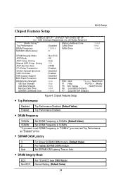
... USB Controller USB Legacy Support BOS Flash Protection DRAM Drive Strength MD Bus Strength CAS Bus Strength Memory Data Drive SDRAM Command Drive : Non-ECC : 4X : Auto : CB : 64MB : Enabled : Disabled : Enabled : Disabled : Disabled : Auto : High : High : 6mA : 16mA ESC : Quit Select Item F1 : Help PU/PD+/-/ : Modify F5 :Old Values (Shift)F2:Color F6 : Load BIOS Defaults F7 : Load SETUP Defaults Figure 4: Chipset Features Setup • Top Performance Disabled Enabled Top Performance Disabled. (Default Value) Top Performance Enabled. • DRAM Frequency 100MHz Set DRAM...
... USB Controller USB Legacy Support BOS Flash Protection DRAM Drive Strength MD Bus Strength CAS Bus Strength Memory Data Drive SDRAM Command Drive : Non-ECC : 4X : Auto : CB : 64MB : Enabled : Disabled : Enabled : Disabled : Disabled : Auto : High : High : 6mA : 16mA ESC : Quit Select Item F1 : Help PU/PD+/-/ : Modify F5 :Old Values (Shift)F2:Color F6 : Load BIOS Defaults F7 : Load SETUP Defaults Figure 4: Chipset Features Setup • Top Performance Disabled Enabled Top Performance Disabled. (Default Value) Top Performance Enabled. • DRAM Frequency 100MHz Set DRAM...

User Manual
Page 67
... Set AGP Mode is Auto. (Default Value) Set AGP Comp. If AGP Comp. Set AGP Aperture Size to 64 MB. (Default Value) Set AGP Aperture Size to 8 MB. Driving is 2X. • AGP Comp. Set USB Legacy Support Keyboard / Mouse /Floppy. Driving Auto Manual Set AGP Comp. Manual AGP Comp. Set AGP Aperture Size to 128 MB. Set AGP Aperture Size to 32 MB. Driving is Manual. Disabled USB Legacy Support Function. (Default Value) 55 Set AGP Aperture Size to 256 MB. • PCI Delay Transaction Enabled Disabled Enabled...
... Set AGP Mode is Auto. (Default Value) Set AGP Comp. If AGP Comp. Set AGP Aperture Size to 64 MB. (Default Value) Set AGP Aperture Size to 8 MB. Driving is 2X. • AGP Comp. Set USB Legacy Support Keyboard / Mouse /Floppy. Driving Auto Manual Set AGP Comp. Manual AGP Comp. Set AGP Aperture Size to 128 MB. Set AGP Aperture Size to 32 MB. Driving is Manual. Disabled USB Legacy Support Function. (Default Value) 55 Set AGP Aperture Size to 256 MB. • PCI Delay Transaction Enabled Disabled Enabled...

User Manual
Page 83
... press . The password typed now will appear to confirm the password being disabled. If you select "Always"at "Password Check"in BIOS Features Setup Menu, you will be prompted for the password every time the system is disabled, the system will boot and you can enter Setup freely. AMIBIOS SIMPLE SETUP UTILITY-VERSION 1.21 ( C ) 1999 American Megatrends, Inc. A message "PASSWORD DISABLED" will clear the previously entered password from CMOS memory. 7VX Series Motherboard Set Supervisor / User Password When you...
... press . The password typed now will appear to confirm the password being disabled. If you select "Always"at "Password Check"in BIOS Features Setup Menu, you will be prompted for the password every time the system is disabled, the system will boot and you can enter Setup freely. AMIBIOS SIMPLE SETUP UTILITY-VERSION 1.21 ( C ) 1999 American Megatrends, Inc. A message "PASSWORD DISABLED" will clear the previously entered password from CMOS memory. 7VX Series Motherboard Set Supervisor / User Password When you...

User Manual
Page 88
VIA 4 in 1 Service Pack Utility: Insert the support CD that came with your motherboard into your CD-ROM drive or double-click the CD drive icon in My Computer to bring up the setup screen. 1.Click "VIA 4in 1 Service Pack Utility "item. (1) (2) 3.Click "Next "item. (3) 4.Click "Yes "item. (4) 5.Click "Next". 74 6.Click "Next". Appendix Appendix Appendix A: VIA Series VT82C686A Chipsets Driver Installation A.
VIA 4 in 1 Service Pack Utility: Insert the support CD that came with your motherboard into your CD-ROM drive or double-click the CD drive icon in My Computer to bring up the setup screen. 1.Click "VIA 4in 1 Service Pack Utility "item. (1) (2) 3.Click "Next "item. (3) 4.Click "Yes "item. (4) 5.Click "Next". 74 6.Click "Next". Appendix Appendix Appendix A: VIA Series VT82C686A Chipsets Driver Installation A.

User Manual
Page 95
... Light Emitting Diode Enhanced Parallel Port Complementary Metal Oxide Semiconductor Input / Output Electrostatic Discharge Original Equipment Manufacturer Static Random Access Memory Voltage ID Desktop Management Interface Musical Interface Digital Interface Input Output Advanced Programmable Input Controller Dual Inline Memory Module Dynamic Random Access Memory PCI A.G.P. ACPI POST LAN ECP APM DMA MHz ESCD CPU SMP USB OS ECC IDE SCI LBA EMC BIOS SMI IRQ NIC A.G.P. 7VX Series Motherboard Appendix D: Acronyms Acor. Controller Audio...
... Light Emitting Diode Enhanced Parallel Port Complementary Metal Oxide Semiconductor Input / Output Electrostatic Discharge Original Equipment Manufacturer Static Random Access Memory Voltage ID Desktop Management Interface Musical Interface Digital Interface Input Output Advanced Programmable Input Controller Dual Inline Memory Module Dynamic Random Access Memory PCI A.G.P. ACPI POST LAN ECP APM DMA MHz ESCD CPU SMP USB OS ECC IDE SCI LBA EMC BIOS SMI IRQ NIC A.G.P. 7VX Series Motherboard Appendix D: Acronyms Acor. Controller Audio...


