Gigabyte GA-7PESLX Support and Manuals
Get Help and Manuals for this Gigabyte item
View All Support Options Below
Free Gigabyte GA-7PESLX manuals!
Problems with Gigabyte GA-7PESLX?
Ask a Question
Free Gigabyte GA-7PESLX manuals!
Problems with Gigabyte GA-7PESLX?
Ask a Question
Popular Gigabyte GA-7PESLX Manual Pages
Manual - Page 1
GA-7PESL GA-7PESLX GA-7PESLN
Dual LGA1356 sockets motherboard for Intel® Xeon series processors
User's Manual
Rev. 1001
Manual - Page 3
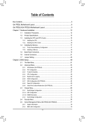
...17 1-4-2 Installing a Memory 18 1-5 Back Panel Connectors 19 1-6 Internal Connectors 21 1-7 Jumper Setting 40
Chapter 2 BIOS Setup 49 2-1 The Main Menu 51 2-2 Advanced Menu 53
2-2-1 H/W Monitor (GA-7PESLN 55 2-2-2 PCI Configuration...56 2-2-3 Trusted Computing 57 2-2-4 CPU Configuration 58 2-2-5 Runtime Error Logging 62 2-2-6 SATA Configuration 63 2-2-7 SAS Configuration (GA-7PESLX 64...
Manual - Page 9
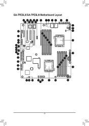
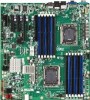
GA-7PESLX/GA-7PESLN Motherboard Layout
43 45 47 49 51 52 1 2 3 4
5
6
44 46 48 50
42
41
40 39 38 37 36 35 34 33 32 31
30 28 28
7
8 9
53
54
55
56
10
57
58
11
12
13
14 15 16
17
18
27 26 25 24 22
21
20
19
23
- 9 -
Manual - Page 10
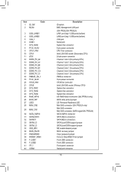
... 1 ID_SW 2 MLAN
Code
3 USB_LANB1 4 USB_LANB2 ...GA-7PESLX only) BIOS write protect jumper LSI Firmware Readiness LED Mini SAS connector (GA-7PESLX only) Mini SAS connector Mini SAS connector (SATA signal/GA-7PESLN) SATA SGPIO connector SATA 3Gb/s connectors SATA 6Gb/s connectors SATA3 port DOM support jumper SATA2 port DOM support jumper ME enable/disable jumper BIOS recovery jumper Clear password...
Manual - Page 14
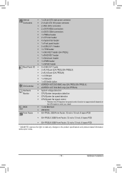
...: EEB Form Factor; 12 inch x 13 inch, 6 layers PCB
ŠŠ GA-7PESLX: EEB Form Factor; 12 inch x 13 inch, 8 layers PCB
ŠŠ GA-7PESLN: EEB Form Factor; 12 inch x 13 inch, 8 layers PCB
* GIGABYTE reserves the right to make any changes to the product specifications and product-related information without prior notice.
- 14 -
Manual - Page 27
... 7 P5V
GA-7PESLX GA-7PESLN
SATA2
SATA4 SATA3 SATA5
• A RAID 0 or RAID 1 configuration requires at least two hard drives. DEBUG DEBUG PORT PORT
11) SATA2/SATA3/SATA4/SATA5 (SATA 3Gb/s Connectors)
12) SATA0/SATA1 (SATA 6Gb/s Connectors)
The SATA connectors conform to 1-2 pin: Pin No.
Hardware Installation
- 27 - Each SATA connector supports a single SATA...
Manual - Page 30
16) COM2 (Serial Port Header) The COM header can provide one serial port via an optional COM port cable. For purchasing the optional COM port cable, please contact the local dealer. GA-7PESL
12 9 10
Pin No. 1 2 3 4 5 6 7 8 9 10
Definition NDCDNSIN NSOUT NDTRGND NDSRNRTSNCTSNRI No Pin
GA-7PESLX GA-7PESLN
Hardware Installation
- 30 -
Manual - Page 33
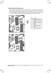
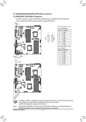
...that interfaces with Hard disk drives (HDDs) to store and retrieve data. Definition
87
1 SGPIO_SATA_DATAOUT1
2 No Pin
3 SGPIO_SATA_DATAOUT0
21
4 GND
5 GND
6 SGPIO_SATA_LOAD
7 NC
8 SGPIO_SATA_CLOCK
GA-7PESLX GA-7PESLN
Hardware Installation
- 33 - 19) SATA_SGPIO (SATA SGPIO Header)
SGPIO is stands for Serial General Purpose Input/Output which is a 4-signal (or 4-wire) bus used between...
Manual - Page 34
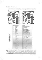
... design may differ by chassis. Hardware Installation ID LED Signal cathode(-)
7 HD+
Hard Disk LED Signal anode (+)
8 F_SYSRDY
System Front board LED Signal
12
9 HD-
A front panel module mainly consists of power switch,
reset switch, power LED, hard drive activity LED, speaker and etc. GA-7PESL
GA-7PESLX GA-7PESLN
Pin No.
LAN1 Link LED...
Manual - Page 35
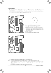
...CMOS when the computer is replaced with local environmental regulations.
- 35 -
Hardware Installation Gently remove the battery from the battery holder and wait for 5 seconds.) 3. GA-7PESLX GA-7PESLN
• Always ...may clear the CMOS values by yourself or uncertain about the battery
model.
• When installing the battery, note the orientation of the positive side (+) and the negative...
Manual - Page 38
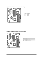
22) RAID_KEY2 (RAID Select Hearder/GA-7PESLX Only)
GA-7PESLX GA-7PESLN
Pin No. 1 2
Definition GPIO GND
23) LED2 (LSI Firmware Readiness LED/GA-7PESLX Only)
GA-7PESLX GA-7PESLN
LED2 Link/Activity:
State Description Blinking LSI firmware is ready
Off
LSI firmware is not ready
Hardware Installation
- 38 -
Manual - Page 39
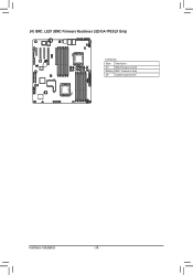
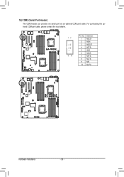
24) BMC_LED1 (BMC Firmware Readiness LED/GA-7PESLX Only)
GA-7PESLX GA-7PESLN
Link/Activity:
State Description
On
BMC firmware is initial
Blinking BMC firmware is ready
Off
System is powered off
Hardware Installation
- 39 -
Manual - Page 40
Hardware Installation
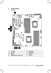
1-7 Jumper Setting
GA-7PESL
1
6 45
3
78 2
1) CLR_CMOS 2) BIOS_WP 3) SSB_ME1 4) ROMST_FRB3 (GA-7PESLX Only)
5) BIOS_RCVR 6) PASSSWORD 7) SATA2_D 8) SATA3_D
- 40 -
Manual - Page 41
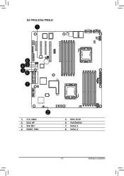
GA-7PESLX/GA-7PESLN
1
6 45 38
7
2
1) CLR_CMOS 2) BIOS_WP 3) SSB_ME1 4) ROMST_FRB3
5) BIOS_RCVR 6) PASSSWORD 7) SATA2_D 8) SATA3_D
- 41 - Hardware Installation
Manual - Page 42
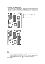
... Setup Exit menu and load factory defaults (select Load Default Values) or manually configure the BIOS settings (refer to Chapter 2, "BIOS Setup," for a few seconds.
1
1-2 Close: Normal operation (Default setting)
2-3 Close: Clear CMOS data. 1
GA-7PESL
GA-7PESLX GA-... CMOS values (e.g. Hardware Installation
- 42 - 1) CLR_CMOS (Clearing CMOS Jumper)
Use this jumper to factory defaults.
Gigabyte GA-7PESLX Reviews
We have not received any reviews for Gigabyte yet.