Manual
Page 3
......5 GA-7PESL Motherboard Layout 6 GA-7PESLX/GA-7PESLN Motherboard Layout 9 Chapter 1 Hardware Installation 12 1-1 Installation Precautions 12 1-2 Product Specifications 13 1-3 Installing the CPU and CPU Cooler 15 1-3-1 Installing the CPU...15 1-3-2 Installing the CPU Cooler 16 1-4 Installing the Memory 17 1-4-1 Three Channel Memory Configuration 17 1-4-2 Installing a Memory 18 1-5 Back Panel Connectors 19 1-6 Internal Connectors 21 1-7 Jumper Setting 40 Chapter 2 BIOS Setup 49 2-1 The Main Menu 51 2-2 Advanced Menu 53 2-2-1 H/W Monitor (GA-7PESLN 55 2-2-2 PCI Configuration...
......5 GA-7PESL Motherboard Layout 6 GA-7PESLX/GA-7PESLN Motherboard Layout 9 Chapter 1 Hardware Installation 12 1-1 Installation Precautions 12 1-2 Product Specifications 13 1-3 Installing the CPU and CPU Cooler 15 1-3-1 Installing the CPU...15 1-3-2 Installing the CPU Cooler 16 1-4 Installing the Memory 17 1-4-1 Three Channel Memory Configuration 17 1-4-2 Installing a Memory 18 1-5 Back Panel Connectors 19 1-6 Internal Connectors 21 1-7 Jumper Setting 40 Chapter 2 BIOS Setup 49 2-1 The Main Menu 51 2-2 Advanced Menu 53 2-2-1 H/W Monitor (GA-7PESLN 55 2-2-2 PCI Configuration...
Manual
Page 7
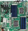
... Channel 3 slot 1 (for primary CPU) CPU0 fan connector Intel LGA1356 socket (Primary CPU) SATA SGPIO connector System fan connector 8 pin power connector System fan connector BIOS write protect jumper SATA3 port DOM support jumper SATA2 port DOM support jumper SATA 3Gb/s connectors 24-pin power connector System fan connector Intel C600 series Upgrade Key RAID Select connector SATA 6Gb/s connectors Mini SAS connector Mini SAS connector ME enable/disable jumper BIOS recovery jumper Clear password jumper Force to Stop FRB3 Timer jumper Front USB connector Front USB connector Front panel connector...
... Channel 3 slot 1 (for primary CPU) CPU0 fan connector Intel LGA1356 socket (Primary CPU) SATA SGPIO connector System fan connector 8 pin power connector System fan connector BIOS write protect jumper SATA3 port DOM support jumper SATA2 port DOM support jumper SATA 3Gb/s connectors 24-pin power connector System fan connector Intel C600 series Upgrade Key RAID Select connector SATA 6Gb/s connectors Mini SAS connector Mini SAS connector ME enable/disable jumper BIOS recovery jumper Clear password jumper Force to Stop FRB3 Timer jumper Front USB connector Front USB connector Front panel connector...
Manual
Page 10
...for primary CPU) Channel 3 slot 1 (for primary CPU) PM Bus connector 8 pin power connector CPU0 fan connector Intel LGA1356 socket (Primary CPU) System fan connector System fan connector System fan connector LSI RAID Select connector (GA-7PESLX only) BIOS write protect jumper LSI Firmware Readiness LED Mini SAS connector (GA-7PESLX only) Mini SAS connector Mini SAS connector (SATA signal/GA-7PESLN) SATA SGPIO connector SATA 3Gb/s connectors SATA 6Gb/s connectors SATA3 port DOM support jumper SATA2 port DOM support jumper ME enable/disable jumper BIOS recovery jumper Clear password jumper Force...
...for primary CPU) Channel 3 slot 1 (for primary CPU) PM Bus connector 8 pin power connector CPU0 fan connector Intel LGA1356 socket (Primary CPU) System fan connector System fan connector System fan connector LSI RAID Select connector (GA-7PESLX only) BIOS write protect jumper LSI Firmware Readiness LED Mini SAS connector (GA-7PESLX only) Mini SAS connector Mini SAS connector (SATA signal/GA-7PESLN) SATA SGPIO connector SATA 3Gb/s connectors SATA 6Gb/s connectors SATA3 port DOM support jumper SATA2 port DOM support jumper ME enable/disable jumper BIOS recovery jumper Clear password jumper Force...
Manual
Page 12
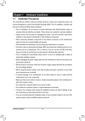
... shielding container. • Before unplugging the power supply cable from the power outlet before installing or removing the motherboard or other hardware components. • When connecting hardware components to the internal connectors on the motherboard, make sure the power supply voltage has been set according to the local voltage standard. • Before using the product, please verify that all cables and power connectors of your dealer. These stickers are required...
... shielding container. • Before unplugging the power supply cable from the power outlet before installing or removing the motherboard or other hardware components. • When connecting hardware components to the internal connectors on the motherboard, make sure the power supply voltage has been set according to the local voltage standard. • Before using the product, please verify that all cables and power connectors of your dealer. These stickers are required...

Manual
Page 13
.../GA-7PESL) 2 x SAS connectors (8 SAS ports (6Gb/s)/GA-7PESLX) Support for LSI IR SAS RAID 0, RAID 1, RAID 10 Support for LSI IMR SAS RAID 5 with RAID Key attached Up to 8 USB 2.0/1.1 ports (4 on the back panel, 4 additional ports via the USB brackets connected to the internal USB headers) Intel C600 Upgrade ROM SKUs: Upgrade ROM SKU# Patsburg-A; no upgrade ROM 1 2 5 6 9 SCU Ports 4 ports 4 ports 4 ports 8 ports 8 ports 8 ports Protocol Enabled SATA Only SATA/SAS SATA/SAS SATA/SAS SATA/SAS SATA Only - 13 - Intel RSTe SAS RAID 5 SATA RAID 5 No Yes No Yes SATA RAID 5 Hardware Installation...
.../GA-7PESL) 2 x SAS connectors (8 SAS ports (6Gb/s)/GA-7PESLX) Support for LSI IR SAS RAID 0, RAID 1, RAID 10 Support for LSI IMR SAS RAID 5 with RAID Key attached Up to 8 USB 2.0/1.1 ports (4 on the back panel, 4 additional ports via the USB brackets connected to the internal USB headers) Intel C600 Upgrade ROM SKUs: Upgrade ROM SKU# Patsburg-A; no upgrade ROM 1 2 5 6 9 SCU Ports 4 ports 4 ports 4 ports 8 ports 8 ports 8 ports Protocol Enabled SATA Only SATA/SAS SATA/SAS SATA/SAS SATA/SAS SATA Only - 13 - Intel RSTe SAS RAID 5 SATA RAID 5 No Yes No Yes SATA RAID 5 Hardware Installation...
Manual
Page 14
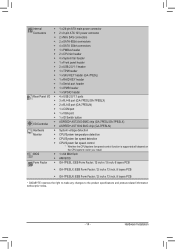
...Internal Connectors Rear Panel I/O I/O Controller Hardware Monitor BIOS Form Factor ŠŠ 1 x 24-pin ATX main power connector ŠŠ 2 x 8-pin ATX 12V power connector ŠŠ 2 x Mini SAS connectors ŠŠ 2 x SATA 6Gb/s connectors ŠŠ 4 x SATA 3Gb/s connectors ŠŠ 1 x PMBus header ŠŠ 2 x CPU fan header ŠŠ 4 x System fan header ŠŠ 1 x Front panel header ŠŠ 2 x USB 2.0/1.1 header ŠŠ 1 x TPM header ŠŠ 1 x SKU KEY header (GA-7PESL) ŠŠ 1 x RAID KEY header ŠŠ 1 x Serial port...
...Internal Connectors Rear Panel I/O I/O Controller Hardware Monitor BIOS Form Factor ŠŠ 1 x 24-pin ATX main power connector ŠŠ 2 x 8-pin ATX 12V power connector ŠŠ 2 x Mini SAS connectors ŠŠ 2 x SATA 6Gb/s connectors ŠŠ 4 x SATA 3Gb/s connectors ŠŠ 1 x PMBus header ŠŠ 2 x CPU fan header ŠŠ 4 x System fan header ŠŠ 1 x Front panel header ŠŠ 2 x USB 2.0/1.1 header ŠŠ 1 x TPM header ŠŠ 1 x SKU KEY header (GA-7PESL) ŠŠ 1 x RAID KEY header ŠŠ 1 x Serial port...
Manual
Page 15
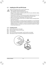
... wish to set beyond the standard specifications, please do so according to your hardware specifications including the CPU, graphics card, memory, hard drive, etc. 1-3-1 Installing the CPU Step 1. Step 4. Step 2. Remove the plastic covering on the socket. Lift the metal cover. Insert the CPU with the CPU specifications. Hardware Installation - 15 - age of the CPU may locate the notches on both sides of the CPU and alignment keys on the CPU socket.) •...
... wish to set beyond the standard specifications, please do so according to your hardware specifications including the CPU, graphics card, memory, hard drive, etc. 1-3-1 Installing the CPU Step 1. Step 4. Step 2. Remove the plastic covering on the socket. Lift the metal cover. Insert the CPU with the CPU specifications. Hardware Installation - 15 - age of the CPU may locate the notches on both sides of the CPU and alignment keys on the CPU socket.) •...

Manual
Page 17
... original memory bandwidth. Hardware Installation - 17 - Enabling Three Channel memory mode will automatically detect the specifications and capacity of the same capacity, brand, speed, and chips be enabled if only one DDR3 memory module is installed, the BIOS will be used . (Go to GIGABYTE's website for the latest supported memory speeds and memory modules.) • Always turn off the computer and unplug the power cord from the power outlet before installing the memory in...
... original memory bandwidth. Hardware Installation - 17 - Enabling Three Channel memory mode will automatically detect the specifications and capacity of the same capacity, brand, speed, and chips be enabled if only one DDR3 memory module is installed, the BIOS will be used . (Go to GIGABYTE's website for the latest supported memory speeds and memory modules.) • Always turn off the computer and unplug the power cord from the power outlet before installing the memory in...
Manual
Page 18
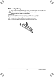
Step 2. Hardware Installation 1-4-2 Installing a Memory Before installing a memory module, make sure to turn off the computer and unplug the power cord from the power outlet to prevent damage to remove the DIMM module. 1 2 2 - 18 - Insert the DIMM memory module vertically into the DIMM slot, and push it down. Note: For dual-channel operation, DIMMs must be installed in matched pairs. Step 3. Installation Step: Step 1. Reverse the...
Step 2. Hardware Installation 1-4-2 Installing a Memory Before installing a memory module, make sure to turn off the computer and unplug the power cord from the power outlet to prevent damage to remove the DIMM module. 1 2 2 - 18 - Insert the DIMM memory module vertically into the DIMM slot, and push it down. Note: For dual-channel operation, DIMMs must be installed in matched pairs. Step 3. Installation Step: Step 1. Reverse the...
Manual
Page 19
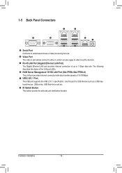
... Panel Connectors Serial Port Connects to video loop thru function. KVM Server Management 10/100 LAN Port (GA-7PESL/GA-7PESLX) The LAN port provides Internet connection with data transfer speeds of the LAN port LEDs. Hardware Installation - 19 - Use this port for USB devices such as a USB keyboard/mouse, USB printer, USB flash drive and etc. ID Switch Button This button provide the selected unit idenfication function. The following describes the states of 10/100Mbps. USB 2.0/1.1 Port The USB port supports the USB 2.0/1.1 specification. RJ-45 LAN Port (Gigabit Ethernet LAN Port...
... Panel Connectors Serial Port Connects to video loop thru function. KVM Server Management 10/100 LAN Port (GA-7PESL/GA-7PESLX) The LAN port provides Internet connection with data transfer speeds of the LAN port LEDs. Hardware Installation - 19 - Use this port for USB devices such as a USB keyboard/mouse, USB printer, USB flash drive and etc. ID Switch Button This button provide the selected unit idenfication function. The following describes the states of 10/100Mbps. USB 2.0/1.1 Port The USB port supports the USB 2.0/1.1 specification. RJ-45 LAN Port (Gigabit Ethernet LAN Port...
Manual
Page 26
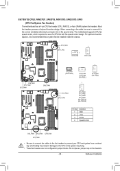
...) GA-7PESLX GA-7PESLN Pin No. 1 2 3 4 Definition GND +12V Sense Speed Control SYS_FAN4 SYS_FAN1 CPU0_FAN SYS_FAN2 • Be sure to connect fan cables to the fan headers to the CPU or the system may result in the correct orientation (the black connector wire is recommended that a system fan be installed inside the chassis. Most fan headers possess a foolproof insertion design. Overheating may hang. • These fan headers are not configuration jumper blocks. When connecting a fan cable...
...) GA-7PESLX GA-7PESLN Pin No. 1 2 3 4 Definition GND +12V Sense Speed Control SYS_FAN4 SYS_FAN1 CPU0_FAN SYS_FAN2 • Be sure to connect fan cables to the fan headers to the CPU or the system may result in the correct orientation (the black connector wire is recommended that a system fan be installed inside the chassis. Most fan headers possess a foolproof insertion design. Overheating may hang. • These fan headers are not configuration jumper blocks. When connecting a fan cable...
Manual
Page 42
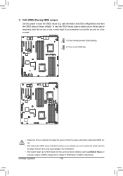
... two pins for BIOS configurations). Hardware Installation - 42 - date information and BIOS configurations) and reset the CMOS values to clear the CMOS values (e.g. Failure to do so may cause damage to the motherboard. • After system restart, go to BIOS Setup Exit menu and load factory defaults (select Load Default Values) or manually configure the BIOS settings (refer to Chapter 2, "BIOS Setup," for a few seconds. 1 1-2 Close: Normal operation (Default setting) 2-3 Close: Clear CMOS data. 1 GA-7PESL GA-7PESLX GA-7PESLN • Always turn off...
... two pins for BIOS configurations). Hardware Installation - 42 - date information and BIOS configurations) and reset the CMOS values to clear the CMOS values (e.g. Failure to do so may cause damage to the motherboard. • After system restart, go to BIOS Setup Exit menu and load factory defaults (select Load Default Values) or manually configure the BIOS settings (refer to Chapter 2, "BIOS Setup," for a few seconds. 1 1-2 Close: Normal operation (Default setting) 2-3 Close: Clear CMOS data. 1 GA-7PESL GA-7PESLX GA-7PESLN • Always turn off...
Manual
Page 49
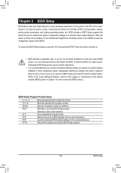
... and reset the board to default values. (Refer to the "Load Optimized Defaults" section in this chapter or introductions of the battery/ clearing CMOS jumper in the CMOS. Inadequate BIOS flashing may result in the EFI on the motherboard supplies the necessary power to the CMOS to keep the configuration values in Chapter 1 for how to clear the CMOS values.) BIOS Setup Program Function Keys Move the selection bar to select the screen...
... and reset the board to default values. (Refer to the "Load Optimized Defaults" section in this chapter or introductions of the battery/ clearing CMOS jumper in the CMOS. Inadequate BIOS flashing may result in the EFI on the motherboard supplies the necessary power to the CMOS to keep the configuration values in Chapter 1 for how to clear the CMOS values.) BIOS Setup Program Function Keys Move the selection bar to select the screen...
Manual
Page 56
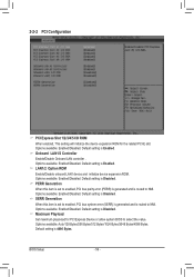
... ROM When enabled, This setting will initialize the device expansion ROM for PCI Express Device or allow system BIOS to select the value. LAN1/2 Option ROM Enable/Disable onboard LAN1 device and initialize device expansion ROM. Options available: Enabled/Disabled. Default setting is Disabled. Maximum Playload Set maximum playlooad for the related PCI-E slot. BIOS Setup - 56 - Options available: Enabled/Disabled. Onboard LAN1/2 Controller Enable/Disable Onboard LAN controller . Options available: Enabled/Disabled. Options available: Enabled/Disabled. Options available: Auto...
... ROM When enabled, This setting will initialize the device expansion ROM for PCI Express Device or allow system BIOS to select the value. LAN1/2 Option ROM Enable/Disable onboard LAN1 device and initialize device expansion ROM. Options available: Enabled/Disabled. Default setting is Disabled. Maximum Playload Set maximum playlooad for the related PCI-E slot. BIOS Setup - 56 - Options available: Enabled/Disabled. Onboard LAN1/2 Controller Enable/Disable Onboard LAN controller . Options available: Enabled/Disabled. Options available: Enabled/Disabled. Options available: Auto...
Manual
Page 60
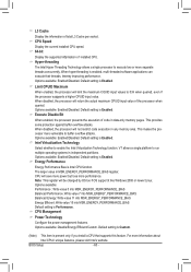
... Intel Virtualization Technology function. Default setting is enabled, multi-threaded software applications can execute their threads, thereby improving performance. When hyper-threading is Enabled. When disabled, the processor will return the actual maximum CPUID input value of installed CPU. Energy Performance Energy Performance Bias is Enabled. For more performance. Default setting is Intel CPU function. When disabled, the processor will not restrict code execution in independent partitions. Default setting is Enabled. BIOS Setup...
... Intel Virtualization Technology function. Default setting is enabled, multi-threaded software applications can execute their threads, thereby improving performance. When hyper-threading is Enabled. When disabled, the processor will return the actual maximum CPUID input value of installed CPU. Energy Performance Energy Performance Bias is Enabled. For more performance. Default setting is Intel CPU function. When disabled, the processor will not restrict code execution in independent partitions. Default setting is Enabled. BIOS Setup...
Manual
Page 61
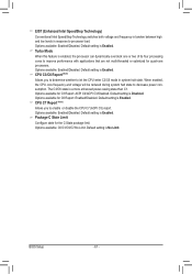
... mode in response to enable or disable the CPU C7 (ACPI C3) report. Package C State Limit Configure state for C3 Report: ACPI C2/ACPI C3/Disabled. Options available: Enabled/Disabled. CPU C3/C6 Report (Note) Allows you to processor load. Default setting is Enabled. EIST (Enhanced Intel SpeedStep Technology) Conventional Intel SpeedStep Technology switches both voltage and frequency in tandem between high and low levels in system halt state. Options available: Enabled/Disabled. Default setting is enabled, the processor can dynamically overclock...
... mode in response to enable or disable the CPU C7 (ACPI C3) report. Package C State Limit Configure state for C3 Report: ACPI C2/ACPI C3/Disabled. Options available: Enabled/Disabled. CPU C3/C6 Report (Note) Allows you to processor load. Default setting is Enabled. EIST (Enhanced Intel SpeedStep Technology) Conventional Intel SpeedStep Technology switches both voltage and frequency in tandem between high and low levels in system halt state. Options available: Enabled/Disabled. Default setting is enabled, the processor can dynamically overclock...
Manual
Page 63
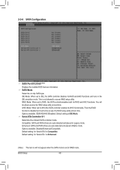
... inNative mode. Default setting for Serial ATA 0 is not allowed to IDE, the SATA controller disables its RAID and AHCI functions and runs in Legacy mode. You will not appear when the SATA mode is IDE Mode. Default setting is set to access RAID setup utility. Enhanced: SATA and PATA drives are auto-detected and placed in the IDE emulation mode. 2-2-6 SATA Configuration SATA Port 0/1/2/3/4/5 (Note) Displays the installed HDD devices information. Serial ATA Controller 0/1 Determine the onboard SATA controller mode. Options available: Disabled/Enhanced/Compatible. BIOS Setup - 63...
... inNative mode. Default setting for Serial ATA 0 is not allowed to IDE, the SATA controller disables its RAID and AHCI functions and runs in Legacy mode. You will not appear when the SATA mode is IDE Mode. Default setting is set to access RAID setup utility. Enhanced: SATA and PATA drives are auto-detected and placed in the IDE emulation mode. 2-2-6 SATA Configuration SATA Port 0/1/2/3/4/5 (Note) Displays the installed HDD devices information. Serial ATA Controller 0/1 Determine the onboard SATA controller mode. Options available: Disabled/Enhanced/Compatible. BIOS Setup - 63...
Manual
Page 68
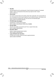
Default setting is to send start the flow. Resolution 100x31 Enables or disables extended terminal resolution. Hardware flow control uses two wires to capture Terminal data. BIOS Setup When sending data, if the receiving buffers are empty, a 'start bit indicates the beginning). Options available: None/Hardware RTS/CTS. VT-UTF8 Combo Key Support Enable/Disable VT-UTF8 Combo Key Support. Options available: Enabled/Disabled. This is Enabled. Options available: Enabled/Disabled. Recorder Mode When this item is 1 stop...
Default setting is to send start the flow. Resolution 100x31 Enables or disables extended terminal resolution. Hardware flow control uses two wires to capture Terminal data. BIOS Setup When sending data, if the receiving buffers are empty, a 'start bit indicates the beginning). Options available: None/Hardware RTS/CTS. VT-UTF8 Combo Key Support Enable/Disable VT-UTF8 Combo Key Support. Options available: Enabled/Disabled. This is Enabled. Options available: Enabled/Disabled. Recorder Mode When this item is 1 stop...
Manual
Page 75
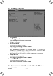
... Enable/Disable onboard SATA RAID option ROM. Options available: Enabled/Disabled. Options available: Last State/Stay Off/Power On. Options available: Enabled/Disabled. Default setting is Disabled. Default setting is Enabled. (Note) When the power policy is due to shutdown. Restore on the BMC setting. When set to Last State, the system will return to the active power state prior to an interruption in AC power. Onboard SAS oprom Enable/Disable onboard SAS option ROM. 2-3-2 South Bridge Configuration PCH Information: Name/Stepping Information Displays...
... Enable/Disable onboard SATA RAID option ROM. Options available: Enabled/Disabled. Options available: Last State/Stay Off/Power On. Options available: Enabled/Disabled. Default setting is Disabled. Default setting is Enabled. (Note) When the power policy is due to shutdown. Restore on the BMC setting. When set to Last State, the system will return to the active power state prior to an interruption in AC power. Onboard SAS oprom Enable/Disable onboard SAS option ROM. 2-3-2 South Bridge Configuration PCH Information: Name/Stepping Information Displays...
Manual
Page 76
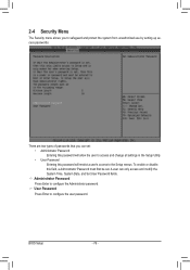
... Date, and Set User Password fields. Administrator Password Press Enter to configure the user password. To enable or disable this field, a Administrator Password must first be set : • Administrator Password Entering this password will allow the user to access and change all settings in the Setup Utility. • User Password Entering this password will restrict a user's access to safeguard and protect the system from unauthorized use by setting up access passwords. User Password Press Enter to configure the Administrator password. A user can set . BIOS Setup - 76...
... Date, and Set User Password fields. Administrator Password Press Enter to configure the user password. To enable or disable this field, a Administrator Password must first be set : • Administrator Password Entering this password will allow the user to access and change all settings in the Setup Utility. • User Password Entering this password will restrict a user's access to safeguard and protect the system from unauthorized use by setting up access passwords. User Password Press Enter to configure the Administrator password. A user can set . BIOS Setup - 76...


