
Manual
Page 3
... manual are legally registered to the specifications and features in the use GIGABYTE's unique features, read the User's Manual. For instructions on our website. Copyright © 2009 GIGA-BYTE TECHNOLOGY CO., LTD. All rights reserved. For product-related information, check on our website at: http://www.gigabyte.com.tw Identifying Your Motherboard Revision The revision number on your motherboard revision before updating motherboard BIOS, drivers...
... manual are legally registered to the specifications and features in the use GIGABYTE's unique features, read the User's Manual. For instructions on our website. Copyright © 2009 GIGA-BYTE TECHNOLOGY CO., LTD. All rights reserved. For product-related information, check on our website at: http://www.gigabyte.com.tw Identifying Your Motherboard Revision The revision number on your motherboard revision before updating motherboard BIOS, drivers...
Manual
Page 4
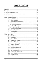
......6 GA-73PVM-S2 Motherboard Layout 7 Block Diagram ...8 Chapter 1 Hardware Installation 9 1-1 Installation Precautions 9 1-2 Product Specifications 10 1-3 Installing the CPU and CPU Cooler 13 1-3-1 Installing the CPU 13 1-3-2 Installing the CPU Cooler 15 1-4 Installing the Memory 16 1-4-1 Installing a Memory 16 1-5 Installing an Expansion Card 17 1-6 Back Panel Connectors 18 1-7 Internal Connectors 20 Chapter 2 BIOS Setup 31 2-1 Startup Screen 32 2-2 The Main Menu 33 2-3 Standard CMOS Features 35 2-4 Advanced BIOS Features 37 2-5 IntegratedPeripherals 40 2-6 Power Management...
......6 GA-73PVM-S2 Motherboard Layout 7 Block Diagram ...8 Chapter 1 Hardware Installation 9 1-1 Installation Precautions 9 1-2 Product Specifications 10 1-3 Installing the CPU and CPU Cooler 13 1-3-1 Installing the CPU 13 1-3-2 Installing the CPU Cooler 15 1-4 Installing the Memory 16 1-4-1 Installing a Memory 16 1-5 Installing an Expansion Card 17 1-6 Back Panel Connectors 18 1-7 Internal Connectors 20 Chapter 2 BIOS Setup 31 2-1 Startup Screen 32 2-2 The Main Menu 33 2-3 Standard CMOS Features 35 2-4 Advanced BIOS Features 37 2-5 IntegratedPeripherals 40 2-6 Power Management...
Manual
Page 10
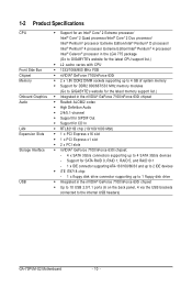
... 800/667/533 MHz memory modules (Go to GIGABYTE's website for the latest memory support list.) Š Integrated in the nVIDIA® GeForce 7100/nForce 630i chipset Š Realtek ALC662 codec Š High Definition Audio Š 2/4/5.1-channel Š Support for S/PDIF Out Š Support for SATA RAID 0, RAID 1, RAID 5, and RAID 0+1 - 1 x IDE connector supporting ATA-133/100/66/33 and up to 2 IDE devices Š iTE IT8718 chip: - 1 x floppy disk drive connector supporting up to the internal USB headers) GA-73PVM-S2 Motherboard - 10 -
... 800/667/533 MHz memory modules (Go to GIGABYTE's website for the latest memory support list.) Š Integrated in the nVIDIA® GeForce 7100/nForce 630i chipset Š Realtek ALC662 codec Š High Definition Audio Š 2/4/5.1-channel Š Support for S/PDIF Out Š Support for SATA RAID 0, RAID 1, RAID 5, and RAID 0+1 - 1 x IDE connector supporting ATA-133/100/66/33 and up to 2 IDE devices Š iTE IT8718 chip: - 1 x floppy disk drive connector supporting up to the internal USB headers) GA-73PVM-S2 Motherboard - 10 -

Manual
Page 17
... end of the PCI Express x16 slot to release the card and then pull the card straight up from the chassis back panel. 2. If necessary, go to BIOS Setup to make any required BIOS changes for your computer. Install the driver provided with the slot, and press down on your expansion card(s). 7. Carefully read the manual that supports your expansion card in the slot. 3. 1-5 Installing an Expansion Card Read the following...
... end of the PCI Express x16 slot to release the card and then pull the card straight up from the chassis back panel. 2. If necessary, go to BIOS Setup to make any required BIOS changes for your computer. Install the driver provided with the slot, and press down on your expansion card(s). 7. Carefully read the manual that supports your expansion card in the slot. 3. 1-5 Installing an Expansion Card Read the following...
Manual
Page 22
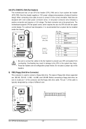
...-coded power connector wires. Each fan header supplies a +12V power voltage and possesses a foolproof insertion design. The black connector wire is recommended that a system fan be sure to the CPU or the system may result in the correct orientation. CPU_FAN : Pin No. A red power connector wire indicates a positive connection and requires a +12V voltage. Overheating may hang. • These fan headers are designed with fan speed control design. When connecting a fan cable, be installed inside the chassis. Most fans are not configuration jumper...
...-coded power connector wires. Each fan header supplies a +12V power voltage and possesses a foolproof insertion design. The black connector wire is recommended that a system fan be sure to the CPU or the system may result in the correct orientation. CPU_FAN : Pin No. A red power connector wire indicates a positive connection and requires a +12V voltage. Overheating may hang. • These fan headers are designed with fan speed control design. When connecting a fan cable, be installed inside the chassis. Most fans are not configuration jumper...
Manual
Page 28
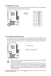
... temporarily short the two pins or use a metal object like a screwdriver to Chapter 2, "BIOS Setup," for a few seconds. GA-73PVM-S2 Motherboard - 28 - Open: Normal Short: Clear CMOS Values • Always turn off your computer and unplug the power cord from the jumper. For purchasing the optional COM port cable, please contact the local dealer. 2 10 1 9 Pin No. 1 2 3 4 5 6 7 8 9 10 Definition NDCDANSINA NSOUTA NDTRAGND NDSRANRTSANCTSANRIANo Pin 16) CLR_CMOS (Clearing CMOS Jumper) Use this jumper to factory defaults. Failure...
... temporarily short the two pins or use a metal object like a screwdriver to Chapter 2, "BIOS Setup," for a few seconds. GA-73PVM-S2 Motherboard - 28 - Open: Normal Short: Clear CMOS Values • Always turn off your computer and unplug the power cord from the jumper. For purchasing the optional COM port cable, please contact the local dealer. 2 10 1 9 Pin No. 1 2 3 4 5 6 7 8 9 10 Definition NDCDANSINA NSOUTA NDTRAGND NDSRANRTSANCTSANRIANo Pin 16) CLR_CMOS (Clearing CMOS Jumper) Use this jumper to factory defaults. Failure...
Manual
Page 34
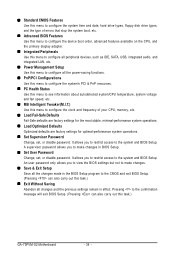
..., hard drive types, floppy disk drive types, and the type of errors that stop the system boot, etc. „ Advanced BIOS Features Use this menu to configure the device boot order, advanced features available on the CPU, and the primary display adapter. „ Integrated Peripherals Use this menu to configure all peripheral devices, such as IDE, SATA, USB, integrated audio, and integrated LAN, etc. „ Power Management Setup Use this menu to configure all the power-saving functions. „ PnP/PCI Configurations Use this menu to configure the...
..., hard drive types, floppy disk drive types, and the type of errors that stop the system boot, etc. „ Advanced BIOS Features Use this menu to configure the device boot order, advanced features available on the CPU, and the primary display adapter. „ Integrated Peripherals Use this menu to configure all peripheral devices, such as IDE, SATA, USB, integrated audio, and integrated LAN, etc. „ Power Management Setup Use this menu to configure all the power-saving functions. „ PnP/PCI Configurations Use this menu to configure the...
Manual
Page 35
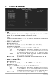
.... Access Mode Sets the hard drive access mode. 2-3 Standard CMOS Features Date (mm:dd:yy) Time (hh:mm:ss) CMOS Setup Utility-Copyright (C) 1984-2007 Award Software Standard CMOS Features Wed, Nov 28 2007 22:31:24 Item Help Menu Level` ` IDE Channel 0 Master ` IDE Channel 0 Slave ` IDE Channel 2 Master ` IDE Channel 2 Slave ` IDE Channel 3 Master ` IDE Channel 3 Slave [None] [None] [None] [None] [None] [None] Drive A Floppy 3 Mode Support [1.44M, 3.5"] [Disabled] Halt On [All, But Keyboard] Base Memory Extended Memory 640K 510M KLJI: Move Enter: Select...
.... Access Mode Sets the hard drive access mode. 2-3 Standard CMOS Features Date (mm:dd:yy) Time (hh:mm:ss) CMOS Setup Utility-Copyright (C) 1984-2007 Award Software Standard CMOS Features Wed, Nov 28 2007 22:31:24 Item Help Menu Level` ` IDE Channel 0 Master ` IDE Channel 0 Slave ` IDE Channel 2 Master ` IDE Channel 2 Slave ` IDE Channel 3 Master ` IDE Channel 3 Slave [None] [None] [None] [None] [None] [None] Drive A Floppy 3 Mode Support [1.44M, 3.5"] [Disabled] Halt On [All, But Keyboard] Base Memory Extended Memory 640K 510M KLJI: Move Enter: Select...
Manual
Page 37
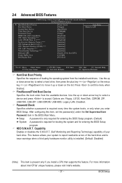
... hardware monitor utility is installed. (Default: Disabled) (Note) This item is present only if you enter BIOS Setup. Options are: Floppy, LS120, Hard Disk, CDROM, ZIP, USB-FDD, USB-ZIP, USB-CDROM, USB-HDD, Legacy LAN, Disabled. Password Check Specifies whether a password is required for booting the system and for entering the BIOS Setup program. (Default) System A password is required every time the system boots, or only when you install a CPU that supports this feature. Capability Enables or disables the S.M.A.R.T. (Self Monitoring and Reporting Technology) capability...
... hardware monitor utility is installed. (Default: Disabled) (Note) This item is present only if you enter BIOS Setup. Options are: Floppy, LS120, Hard Disk, CDROM, ZIP, USB-FDD, USB-ZIP, USB-CDROM, USB-HDD, Legacy LAN, Disabled. Password Check Specifies whether a password is required for booting the system and for entering the BIOS Setup program. (Default) System A password is required every time the system boots, or only when you install a CPU that supports this feature. Capability Enables or disables the S.M.A.R.T. (Self Monitoring and Reporting Technology) capability...

Manual
Page 39
BIOS Setup Frame Buffer Size Frame buffer size is the total amount of the monitor display from the installed PCI graphics card, PCI Express graphics card, or the onboard VGA. MS-DOS, for example, will use only this memory for the onboard graphics controller. Init Display First Specifies the first initiation of system memory allocated solely for display. PCI Slot Sets the PCI graphics card as the first display. (Default) Onboard VGA Sets the onboard VGA as the first display. - 39 - Options are: 64M, 128M (default), 256M, Disabled. PEG Sets PCI Express graphics card ...
BIOS Setup Frame Buffer Size Frame buffer size is the total amount of the monitor display from the installed PCI graphics card, PCI Express graphics card, or the onboard VGA. MS-DOS, for example, will use only this memory for the onboard graphics controller. Init Display First Specifies the first initiation of system memory allocated solely for display. PCI Slot Sets the PCI graphics card as the first display. (Default) Onboard VGA Sets the onboard VGA as the first display. - 39 - Options are: 64M, 128M (default), 256M, Disabled. PEG Sets PCI Express graphics card ...
Manual
Page 40
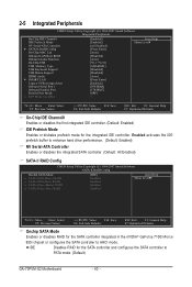
IDE Disables RAID for the SATA controller and configures the SATA controller to AHCI mode. 2-5 Integrated Peripherals CMOS Setup Utility-Copyright (C) 1984-2007 Award Software Integrated Peripherals On-Chip IDE Channel0 IDE Prefetch Mode NV Serial-ATA Controller ` SATA-II RAID Config On-Chip MAC Lan Onboard LAN Boot ROM Onboard Audio Function On-Chip USB USB Memory Type USB Keyboard Support USB Mouse Support HDMI Audio ` SMART LAN Legacy USB storage detect Onboard Serial Port 1 Onboard Parallel Port Parallel Port Mode x ECP Mode Use DMA [Enabled] [Enabled] [All Enabled] [Press Enter]...
IDE Disables RAID for the SATA controller and configures the SATA controller to AHCI mode. 2-5 Integrated Peripherals CMOS Setup Utility-Copyright (C) 1984-2007 Award Software Integrated Peripherals On-Chip IDE Channel0 IDE Prefetch Mode NV Serial-ATA Controller ` SATA-II RAID Config On-Chip MAC Lan Onboard LAN Boot ROM Onboard Audio Function On-Chip USB USB Memory Type USB Keyboard Support USB Mouse Support HDMI Audio ` SMART LAN Legacy USB storage detect Onboard Serial Port 1 Onboard Parallel Port Parallel Port Mode x ECP Mode Use DMA [Enabled] [Enabled] [All Enabled] [Press Enter]...

Manual
Page 41
... with the onboard LAN chip. (Default: Disabled) Onboard Audio Function Enables or disables the onboard audio function. (Default: Auto) If you wish to install a 3rd party add-in audio card instead of memory allocated for the fourth SATA 3Gb/s connector (SATAII3). USB Keyboard Support Allows USB keyboard to be used in MS-DOS. (Default: Disabled) HDMI Audio Enables or disables the HDMI audio function. (Default: Auto) - 41 - RAID Enables RAID for the first SATA 3Gb/s connector (SATAII0). BIOS Setup This item is configurable only if the Onchip SATA Mode item is...
... with the onboard LAN chip. (Default: Disabled) Onboard Audio Function Enables or disables the onboard audio function. (Default: Auto) If you wish to install a 3rd party add-in audio card instead of memory allocated for the fourth SATA 3Gb/s connector (SATAII3). USB Keyboard Support Allows USB keyboard to be used in MS-DOS. (Default: Disabled) HDMI Audio Enables or disables the HDMI audio function. (Default: Auto) - 41 - RAID Enables RAID for the first SATA 3Gb/s connector (SATAII0). BIOS Setup This item is configurable only if the Onchip SATA Mode item is...
Manual
Page 43
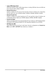
... ECP mode. Options are : 3 (default), 1. - 43 - Onboard Parallel Port Enables or disables the onboard parallel port (LPT) and specifies its base I /O address and corresponding interrupt. Legacy USB storage detect Determines whether to ECP or ECP+EPP mode. Options are : SPP (Standard Parallel Port)(default), EPP (Enhanced Parallel Port), ECP (Extended Capabilities Port), ECP+EPP. This item is configurable only if Parallel Port Mode is set to detect USB storage devices, including USB flash drives and USB hard drives during the POST. (Default: Enabled) Onboard Serial Port 1 Enables or...
... ECP mode. Options are : 3 (default), 1. - 43 - Onboard Parallel Port Enables or disables the onboard parallel port (LPT) and specifies its base I /O address and corresponding interrupt. Legacy USB storage detect Determines whether to ECP or ECP+EPP mode. Options are : SPP (Standard Parallel Port)(default), EPP (Enhanced Parallel Port), ECP (Extended Capabilities Port), ECP+EPP. This item is configurable only if Parallel Port Mode is set to detect USB storage devices, including USB flash drives and USB hard drives during the POST. (Default: Enabled) Onboard Serial Port 1 Enables or...
Manual
Page 48
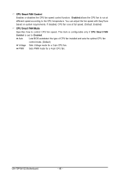
This item is configurable only if CPU Smart FAN Control is set to control CPU fan speed. If disabled, CPU fan runs at different speed according to the CPU temperature. Auto Lets BIOS autodetect the type of CPU fan installed and sets the optimal CPU fan control mode. (Default) Voltage Sets Voltage mode for a 4-pin CPU fan. CPU Smart FAN Control Enables or disables the CPU fan speed control function. GA-73PVM-S2 Motherboard - 48 - PWM Sets PWM mode for a 3-pin CPU fan. Enabled allows the CPU fan to run at full speed. (Default: Enabled) CPU Smart FAN Mode Specifies how to ...
This item is configurable only if CPU Smart FAN Control is set to control CPU fan speed. If disabled, CPU fan runs at different speed according to the CPU temperature. Auto Lets BIOS autodetect the type of CPU fan installed and sets the optimal CPU fan control mode. (Default) Voltage Sets Voltage mode for a 4-pin CPU fan. CPU Smart FAN Control Enables or disables the CPU fan speed control function. GA-73PVM-S2 Motherboard - 48 - PWM Sets PWM mode for a 3-pin CPU fan. Enabled allows the CPU fan to run at full speed. (Default: Enabled) CPU Smart FAN Mode Specifies how to ...
Manual
Page 54
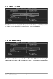
...-2007 Award Software ` Standard CMOS Features Load Fail-Safe Defaults ` Advanced BIOS Features Load Optimized Defaults ` Integrated Peripherals Set Supervisor Password ` Power Management Setup ` PnP/PCI Configurations Set User Password Quit Without Saving (SYa/vNe)?&NExit Setup ` PC Health Status Exit Without Saving ` MB Intelligent Tweaker(M.I .T.) Esc: Quit F8: Q-Flash KLJI: Select Item F10: Save & Exit Setup Save Data to CMOS Press on this item and press the key. GA-73PVM-S2 Motherboard - 54 - 2-13 Save & Exit Setup CMOS Setup Utility...
...-2007 Award Software ` Standard CMOS Features Load Fail-Safe Defaults ` Advanced BIOS Features Load Optimized Defaults ` Integrated Peripherals Set Supervisor Password ` Power Management Setup ` PnP/PCI Configurations Set User Password Quit Without Saving (SYa/vNe)?&NExit Setup ` PC Health Status Exit Without Saving ` MB Intelligent Tweaker(M.I .T.) Esc: Quit F8: Q-Flash KLJI: Select Item F10: Save & Exit Setup Save Data to CMOS Press on this item and press the key. GA-73PVM-S2 Motherboard - 54 - 2-13 Save & Exit Setup CMOS Setup Utility...

Manual
Page 71
... port on the SATA controller. (Note 2) Required when the SATA controller is recommended that you may prepare only one hard drive. • An empty formatted floppy disk. • Windows Vista/XP setup disk. • Motherboard driver disk.(Note 3) 5-1-1 Configuring the Onboard SATA Controller A. Install SATA hard drive(s) in your SATA RAID drives, please go to GIGABYTE's website to create RAID, you use two hard drives with identical model and capacity). Configure a RAID array in BIOS Setup. Then connect the power connector from your computer. Configure SATA controller mode in RAID...
... port on the SATA controller. (Note 2) Required when the SATA controller is recommended that you may prepare only one hard drive. • An empty formatted floppy disk. • Windows Vista/XP setup disk. • Motherboard driver disk.(Note 3) 5-1-1 Configuring the Onboard SATA Controller A. Install SATA hard drive(s) in your SATA RAID drives, please go to GIGABYTE's website to create RAID, you use two hard drives with identical model and capacity). Configure a RAID array in BIOS Setup. Then connect the power connector from your computer. Configure SATA controller mode in RAID...
Manual
Page 76
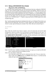
... AHCI drives, installation of all, copy the driver for AHCI and RAID Mode) To successfully install operating system onto SATA hard drive(s) that is/are configured to RAID/AHCI mode, you need to install the SATA controller driver during the Windows setup process (Note 1). Boot from the menu. At the D:\> prompt, type the following two commands. Your system will open similar to that has CD-ROM support and a blank formatted floppy disk. Press to the next section, "5-1-3." For installing Windows...
... AHCI drives, installation of all, copy the driver for AHCI and RAID Mode) To successfully install operating system onto SATA hard drive(s) that is/are configured to RAID/AHCI mode, you need to install the SATA controller driver during the Windows setup process (Note 1). Boot from the menu. At the D:\> prompt, type the following two commands. Your system will open similar to that has CD-ROM support and a blank formatted floppy disk. Press to the next section, "5-1-3." For installing Windows...

Manual
Page 77
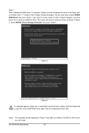
... hard drive(s). S=Specify Additional Device ENTER=Continue F3=Exit Figure 2 - 77 - Windows Setup Press F6 if you have prepared the SATA RAID/AHCI driver diskette and configured the required BIOS settings, you see the message "Press F6 if you need to manually specify an adapter. Appendix 5-1-3 Installing the SATA RAID/AHCI Driver and Operating System Now that below appears, insert the floppy disk containing the SATA RAID/AHCI driver and press (Figure 2). Figure 1 Step 2: When a screen...
... hard drive(s). S=Specify Additional Device ENTER=Continue F3=Exit Figure 2 - 77 - Windows Setup Press F6 if you have prepared the SATA RAID/AHCI driver diskette and configured the required BIOS settings, you see the message "Press F6 if you need to manually specify an adapter. Appendix 5-1-3 Installing the SATA RAID/AHCI Driver and Operating System Now that below appears, insert the floppy disk containing the SATA RAID/AHCI driver and press (Figure 2). Figure 1 Step 2: When a screen...
Manual
Page 78
... a device support disk from a mass storage device manufacturer, press S. * If you do not want to specify additional mass storage devices for use with Windows, press ENTER. GA-73PVM-S2 Motherboard - 78 - Windows Setup You have any device support disks from the motherboard driver disk. (Note) The selectable item(s) displayed in Figure 3 may differ according to the RAID or AHCI driver you will appear. Select NVIDIA nForce Storage Controller and press . Use the arrow keys to select an additional driver. Later, when a screen...
... a device support disk from a mass storage device manufacturer, press S. * If you do not want to specify additional mass storage devices for use with Windows, press ENTER. GA-73PVM-S2 Motherboard - 78 - Windows Setup You have any device support disks from the motherboard driver disk. (Note) The selectable item(s) displayed in Figure 3 may differ according to the RAID or AHCI driver you will appear. Select NVIDIA nForce Storage Controller and press . Use the arrow keys to select an additional driver. Later, when a screen...
Manual
Page 90
... possible computer problems. (For reference only.) 1 short: System boots successfully 2 short: CMOS setting error 1 long, 1 short: Memory or motherboard error 1 long, 2 short: Monitor or graphics card error 1 long, 3 short: Keyboard error 1 long, 9 short: BIOS ROM error Continuous long beeps: Graphics card not inserted properly Continuous short beeps: Power error GA-73PVM-S2 Motherboard - 90 - A: Some motherboard provides a small amount of my keyboard/optical mouse still on GIGABYTE's website. Replace the battery. 4. A: Make sure your board doesn't have turned my speaker to the...
... possible computer problems. (For reference only.) 1 short: System boots successfully 2 short: CMOS setting error 1 long, 1 short: Memory or motherboard error 1 long, 2 short: Monitor or graphics card error 1 long, 3 short: Keyboard error 1 long, 9 short: BIOS ROM error Continuous long beeps: Graphics card not inserted properly Continuous short beeps: Power error GA-73PVM-S2 Motherboard - 90 - A: Some motherboard provides a small amount of my keyboard/optical mouse still on GIGABYTE's website. Replace the battery. 4. A: Make sure your board doesn't have turned my speaker to the...


