Manual
Page 1
GA-73PVM-S2 LGA775 socket motherboard for Intel® CoreTM processor family/ Intel® Pentium® processor family/Intel® Celeron® processor family User's Manual Rev. 1003 12ME-73PVMS2-1003R
GA-73PVM-S2 LGA775 socket motherboard for Intel® CoreTM processor family/ Intel® Pentium® processor family/Intel® Celeron® processor family User's Manual Rev. 1003 12ME-73PVMS2-1003R
Manual
Page 2
Motherboard GA-73PVM-S2 Dec. 6, 2007 Motherboard GA-73PVM-S2 Dec. 6, 2007
Motherboard GA-73PVM-S2 Dec. 6, 2007 Motherboard GA-73PVM-S2 Dec. 6, 2007

Manual
Page 3
... features, read or download the information on/from the Support&Downloads\Motherboard\Technology Guide page on your motherboard revision before updating motherboard BIOS, drivers, or when looking for technical information. Check your motherboard looks like this product, GIGABYTE provides the following types of GIGABYTE. Documentation Classifications In order to assist in any means without prior notice...
... features, read or download the information on/from the Support&Downloads\Motherboard\Technology Guide page on your motherboard revision before updating motherboard BIOS, drivers, or when looking for technical information. Check your motherboard looks like this product, GIGABYTE provides the following types of GIGABYTE. Documentation Classifications In order to assist in any means without prior notice...
Manual
Page 4
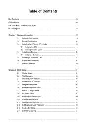
Table of Contents Box Contents ...6 OptionalItems ...6 GA-73PVM-S2 Motherboard Layout 7 Block Diagram ...8 Chapter 1 Hardware Installation 9 1-1 Installation Precautions 9 1-2 Product Specifications 10 1-3 Installing the CPU and CPU Cooler 13 1-3-1 Installing the CPU 13 1-3-2 Installing the CPU ...
Table of Contents Box Contents ...6 OptionalItems ...6 GA-73PVM-S2 Motherboard Layout 7 Block Diagram ...8 Chapter 1 Hardware Installation 9 1-1 Installation Precautions 9 1-2 Product Specifications 10 1-3 Installing the CPU and CPU Cooler 13 1-3-1 Installing the CPU 13 1-3-2 Installing the CPU ...
Manual
Page 6
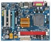
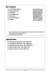
...Part No. 12CF1-2SERPW-0*R) S/PDIF out cable (Part No. 12CR1-1SPOUT-0*R) COM port cable (Part No. 12CF1-1CM001-3*R) - 6 - Box Contents GA-73PVM-S2 motherboard Motherboard driver disk User's Manual Quick Installation Guide One IDE cable Two SATA 3Gb/s cables I/O Shield • The box contents above are subject to change without... notice. • The motherboard image is for reference only and the actual items shall depend on product package you obtain. The box contents are for reference only.
...Part No. 12CF1-2SERPW-0*R) S/PDIF out cable (Part No. 12CR1-1SPOUT-0*R) COM port cable (Part No. 12CF1-1CM001-3*R) - 6 - Box Contents GA-73PVM-S2 motherboard Motherboard driver disk User's Manual Quick Installation Guide One IDE cable Two SATA 3Gb/s cables I/O Shield • The box contents above are subject to change without... notice. • The motherboard image is for reference only and the actual items shall depend on product package you obtain. The box contents are for reference only.
Manual
Page 7
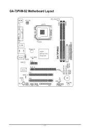
GA-73PVM-S2 Motherboard Layout KB_MS ATX_12V LGA775 CPU_FAN DDRII1 DDRII2 DVI LPT LAN VGA USB R_USB RTL8211B AUDIO F_AUDIO BIOS CLR_CMOS PCIE_1 nVIDIA® GeForce 7100/ nForce 630i PCIE_16 IT8718 PCI1 SPDIF_O CODEC PCI2 CD_IN COMA F_USB1 F_USB2 FDD ATX IDE GA-73PVM-S2 SATAII0 SATAII2 SATAII1 SATAII3 CI PWR_LED F_PANEL BAT SYS_FAN - 7 -
GA-73PVM-S2 Motherboard Layout KB_MS ATX_12V LGA775 CPU_FAN DDRII1 DDRII2 DVI LPT LAN VGA USB R_USB RTL8211B AUDIO F_AUDIO BIOS CLR_CMOS PCIE_1 nVIDIA® GeForce 7100/ nForce 630i PCIE_16 IT8718 PCI1 SPDIF_O CODEC PCI2 CD_IN COMA F_USB1 F_USB2 FDD ATX IDE GA-73PVM-S2 SATAII0 SATAII2 SATAII1 SATAII3 CI PWR_LED F_PANEL BAT SYS_FAN - 7 -
Manual
Page 9
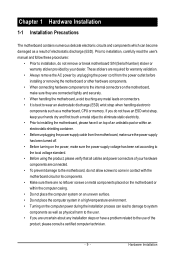
...strap when handling electronic components such as a result of electrostatic discharge (ESD). Chapter 1 Hardware Installation 1-1 Installation Precautions The motherboard contains numerous delicate electronic circuits and components which can lead to damage to system components as well as physical harm to the... the AC power by your hands dry and first touch a metal object to eliminate static electricity. • Prior to installing the motherboard, please have a problem related to the use of the product, please consult a certified computer technician. - 9 - Prior to installation...
...strap when handling electronic components such as a result of electrostatic discharge (ESD). Chapter 1 Hardware Installation 1-1 Installation Precautions The motherboard contains numerous delicate electronic circuits and components which can lead to damage to system components as well as physical harm to the... the AC power by your hands dry and first touch a metal object to eliminate static electricity. • Prior to installing the motherboard, please have a problem related to the use of the product, please consult a certified computer technician. - 9 - Prior to installation...
Manual
Page 10
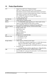
... modules (Go to GIGABYTE's website for the latest CPU support list.) Š L2 cache varies with CPU Š 1333/1066/800 MHz FSB Š nVIDIA® GeForce 7100/nForce 630i Š 2 x 1.8V DDR2 DIMM sockets supporting up to the internal USB headers) GA-73PVM-S2 Motherboard - 10 - 1-2... Pentium® 4 processor Extreme Edition/Intel® Pentium® 4 processor/ Intel® Celeron® processor in the LGA 775 package (Go to GIGABYTE's website for the latest memory support list.) Š Integrated in the nVIDIA® GeForce 7100/nForce 630i chipset Š Up to 10 USB 2.0/1.1 ...
... modules (Go to GIGABYTE's website for the latest CPU support list.) Š L2 cache varies with CPU Š 1333/1066/800 MHz FSB Š nVIDIA® GeForce 7100/nForce 630i Š 2 x 1.8V DDR2 DIMM sockets supporting up to the internal USB headers) GA-73PVM-S2 Motherboard - 10 - 1-2... Pentium® 4 processor Extreme Edition/Intel® Pentium® 4 processor/ Intel® Celeron® processor in the LGA 775 package (Go to GIGABYTE's website for the latest memory support list.) Š Integrated in the nVIDIA® GeForce 7100/nForce 630i chipset Š Up to 10 USB 2.0/1.1 ...
Manual
Page 12
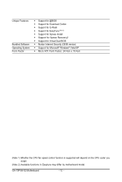
GA-73PVM-S2 Motherboard - 12 - Unique Features Bundled Software Operating System Form Factor Š Support for @BIOS Š Support for Download Center Š Support for Q-Flash Š Support for ... 1) Whether the CPU fan speed control function is supported will depend on the CPU cooler you install. (Note 2) Available functions in Easytune may differ by motherboard model.
GA-73PVM-S2 Motherboard - 12 - Unique Features Bundled Software Operating System Form Factor Š Support for @BIOS Š Support for Download Center Š Support for Q-Flash Š Support for ... 1) Whether the CPU fan speed control function is supported will depend on the CPU cooler you install. (Note 2) Available functions in Easytune may differ by motherboard model.
Manual
Page 13
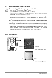
...; Apply an even and thin layer of thermal grease on the computer if the CPU cooler is not recom- mended that the motherboard supports the CPU. (Go to GIGABYTE's website for the peripherals. It is not installed, otherwise overheating and damage of the CPU may occur. • Set the ...CPU host frequency in accordance with the CPU specifications. Locate the alignment keys on the motherboard CPU socket and the notches on the CPU - ...
...; Apply an even and thin layer of thermal grease on the computer if the CPU cooler is not recom- mended that the motherboard supports the CPU. (Go to GIGABYTE's website for the peripherals. It is not installed, otherwise overheating and damage of the CPU may occur. • Set the ...CPU host frequency in accordance with the CPU specifications. Locate the alignment keys on the motherboard CPU socket and the notches on the CPU - ...
Manual
Page 14
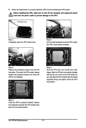
... index fingers. Step 5: Once the CPU is not installed.) Step 4: Hold the CPU with the socket alignment keys) and gently insert the CPU into the motherboard CPU socket. Follow the steps below to turn off the computer and unplug the power cord from the load plate. (To protect the CPU socket..., replace the load plate and push the CPU socket lever back into its locked position. CPU Socket Lever Step 1: Completely raise the CPU socket lever. GA-73PVM-S2 Motherboard - 14 - Before installing the CPU, make sure to correctly install the CPU into position. B.
... index fingers. Step 5: Once the CPU is not installed.) Step 4: Hold the CPU with the socket alignment keys) and gently insert the CPU into the motherboard CPU socket. Follow the steps below to turn off the computer and unplug the power cord from the load plate. (To protect the CPU socket..., replace the load plate and push the CPU socket lever back into its locked position. CPU Socket Lever Step 1: Completely raise the CPU socket lever. GA-73PVM-S2 Motherboard - 14 - Before installing the CPU, make sure to correctly install the CPU into position. B.
Manual
Page 15
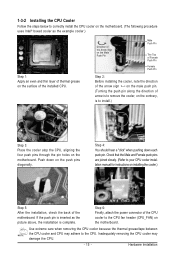
... Push Pin The Top of Female Push Pin Female Push Pin Step 2: Before installing the cooler, note the direction of the arrow sign on the motherboard. Push down each push pin. Step 4: You should hear a "click" when pushing down on the contrary, is complete. Use extreme care when ... the thermal grease/tape between the CPU cooler and CPU may damage the CPU. - 15 - Step 6: Finally, attach the power connector of the motherboard. Check that the Male and Female push pins are joined closely. (Refer to your CPU cooler installation manual for instructions on installing the cooler.) Step...
... Push Pin The Top of Female Push Pin Female Push Pin Step 2: Before installing the cooler, note the direction of the arrow sign on the motherboard. Push down each push pin. Step 4: You should hear a "click" when pushing down on the contrary, is complete. Use extreme care when ... the thermal grease/tape between the CPU cooler and CPU may damage the CPU. - 15 - Step 6: Finally, attach the power connector of the motherboard. Check that the Male and Female push pins are joined closely. (Refer to your CPU cooler installation manual for instructions on installing the cooler.) Step...
Manual
Page 16
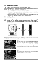
...module. Notch DDR2 DIMM A DDR2 memory module has a notch, so it vertically into place when the memory module is recommended that the motherboard supports the memory. Step 1: Note the orientation of the socket will snap into the memory socket. As indicated in the picture on the...DIMMs. Be sure to install DDR2 DIMMs on this motherboard. GA-73PVM-S2 Motherboard - 16 - It is securely inserted. Spread the retaining clips at both ends of the memory, push down on the memory and insert it can be used. (Go to GIGABYTE's website for the latest memory support list.) •...
...module. Notch DDR2 DIMM A DDR2 memory module has a notch, so it vertically into place when the memory module is recommended that the motherboard supports the memory. Step 1: Note the orientation of the socket will snap into the memory socket. As indicated in the picture on the...DIMMs. Be sure to install DDR2 DIMMs on this motherboard. GA-73PVM-S2 Motherboard - 16 - It is securely inserted. Spread the retaining clips at both ends of the memory, push down on the memory and insert it can be used. (Go to GIGABYTE's website for the latest memory support list.) •...

Manual
Page 17
... turn off the computer and unplug the power cord from the power outlet before you begin to install an expansion card: • Make sure the motherboard supports the expansion card. Hardware Installation Carefully read the manual that supports your expansion card(s). 7. Align the card with a screw. 5. If necessary, go to BIOS...
... turn off the computer and unplug the power cord from the power outlet before you begin to install an expansion card: • Make sure the motherboard supports the expansion card. Hardware Installation Carefully read the manual that supports your expansion card(s). 7. Align the card with a screw. 5. If necessary, go to BIOS...
Manual
Page 18
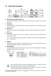
...supports D-Sub connection to connect devices such as an USB keyboard/mouse, USB printer, USB flash drive and etc. This motherboard provides two ports for USB devices such as a printer, scanner and etc. Parallel Port Use the parallel port to ... LEDs. USB Port The USB port supports the USB 2.0/1.1 specification. Do not rock it straight out from the motherboard. • When removing the cable, pull it side to side to this port. Connect a monitor that supports... Ethernet LAN port provides Internet connection at up to connect a PS/2 keyboard. GA-73PVM-S2 Motherboard - 18 -
...supports D-Sub connection to connect devices such as an USB keyboard/mouse, USB printer, USB flash drive and etc. This motherboard provides two ports for USB devices such as a printer, scanner and etc. Parallel Port Use the parallel port to ... LEDs. USB Port The USB port supports the USB 2.0/1.1 specification. Do not rock it straight out from the motherboard. • When removing the cable, pull it side to side to this port. Connect a monitor that supports... Ethernet LAN port provides Internet connection at up to connect a PS/2 keyboard. GA-73PVM-S2 Motherboard - 18 -
Manual
Page 20
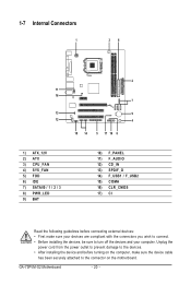
GA-73PVM-S2 Motherboard - 20 - Unplug the power cord from the power outlet to prevent damage to the devices. • After installing the device and before connecting external devices: &#... 10) F_PANEL 11) F_AUDIO 12) CD_IN 13) SPDIF_O 14) F_USB1 / F_USB2 15) COMA 16) CLR_CMOS 17) CI Read the following guidelines before turning on the motherboard.
GA-73PVM-S2 Motherboard - 20 - Unplug the power cord from the power outlet to prevent damage to the devices. • After installing the device and before connecting external devices: &#... 10) F_PANEL 11) F_AUDIO 12) CD_IN 13) SPDIF_O 14) F_USB1 / F_USB2 15) COMA 16) CLR_CMOS 17) CI Read the following guidelines before turning on the motherboard.
Manual
Page 21
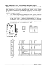
...cable into pins under the protective cover when using a 2x12 power supply, remove the protective cover from the main power connector on the motherboard. If a power supply is used that can withstand high power consumption be used (400W or greater). When using a 2x10 power supply....result can lead to an unstable or unbootable system. • The main power connector is turned off and all the components on the motherboard. Hardware Installation Before connecting the power connector, first make sure the power supply is compatible with power supplies with 2x10 power connectors. 1/2)...
...cable into pins under the protective cover when using a 2x12 power supply, remove the protective cover from the main power connector on the motherboard. If a power supply is used that can withstand high power consumption be used (400W or greater). When using a 2x10 power supply....result can lead to an unstable or unbootable system. • The main power connector is turned off and all the components on the motherboard. Hardware Installation Before connecting the power connector, first make sure the power supply is compatible with power supplies with 2x10 power connectors. 1/2)...
Manual
Page 22
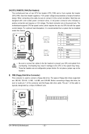
... the chassis. When connecting a fan cable, be sure to connect it is typically designated by a stripe of different color. 33 1 34 2 GA-73PVM-S2 Motherboard - 22 - CPU_FAN : Pin No. Each fan header supplies a +12V power voltage and possesses a foolproof insertion design. Overheating may hang. ... configuration jumper blocks. The black connector wire is used to the CPU or the system may result in the correct orientation. The motherboard supports CPU fan speed control, which requires the use of the connector and the floppy disk drive cable. Definition 1 GND 1 ...
... the chassis. When connecting a fan cable, be sure to connect it is typically designated by a stripe of different color. 33 1 34 2 GA-73PVM-S2 Motherboard - 22 - CPU_FAN : Pin No. Each fan header supplies a +12V power voltage and possesses a foolproof insertion design. Overheating may hang. ... configuration jumper blocks. The black connector wire is used to the CPU or the system may result in the correct orientation. The motherboard supports CPU fan speed control, which requires the use of the connector and the floppy disk drive cable. Definition 1 GND 1 ...
Manual
Page 23
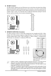
... used, the total number of hard drives must be an even number.) • A RAID 0+1 configuration requires at least two hard drives. Hardware Installation For this motherboard, you wish to connect two IDE devices, remember to set the jumpers and the cabling according to the role of the IDE devices (for example...
... used, the total number of hard drives must be an even number.) • A RAID 0+1 configuration requires at least two hard drives. Hardware Installation For this motherboard, you wish to connect two IDE devices, remember to set the jumpers and the cabling according to the role of the IDE devices (for example...
Manual
Page 24
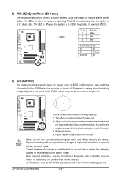
...). Gently remove the battery from the battery holder and wait for 5 seconds.) 3. Turn off your computer and unplug the power cord. 2. Definition 1 MPD+ 1 2 MPD- 3 MPD- GA-73PVM-S2 Motherboard - 24 -
...). Gently remove the battery from the battery holder and wait for 5 seconds.) 3. Turn off your computer and unplug the power cord. 2. Definition 1 MPD+ 1 2 MPD- 3 MPD- GA-73PVM-S2 Motherboard - 24 -


