
Manual
Page 3
... the Support&Downloads\Motherboard\Technology Guide page on your motherboard revision before updating motherboard BIOS, drivers, or when looking for technical information. Documentation Classifications In order to the specifications and features in any form or by GIGABYTE without GIGABYTE's prior written permission. No part of documentations: For detailed product information, carefully read...
... the Support&Downloads\Motherboard\Technology Guide page on your motherboard revision before updating motherboard BIOS, drivers, or when looking for technical information. Documentation Classifications In order to the specifications and features in any form or by GIGABYTE without GIGABYTE's prior written permission. No part of documentations: For detailed product information, carefully read...
Manual
Page 4
...GA-73PVM-S2 Motherboard Layout 7 Block Diagram ...8 Chapter 1 Hardware Installation 9 1-1 Installation Precautions 9 1-2 Product Specifications 10 1-3 Installing the CPU and CPU Cooler 13 1-3-1 Installing the CPU 13 1-3-2 Installing the CPU Cooler 15 1-4 Installing the Memory 16 1-4-1 Installing a Memory 16 1-5 Installing an Expansion Card 17 1-6 Back Panel Connectors 18 1-7 Internal Connectors 20 Chapter 2 BIOS... Setup 31 2-1 Startup Screen 32 2-2 The Main Menu 33 2-3 Standard CMOS Features 35 2-4 Advanced BIOS Features 37 2-5 IntegratedPeripherals...
...GA-73PVM-S2 Motherboard Layout 7 Block Diagram ...8 Chapter 1 Hardware Installation 9 1-1 Installation Precautions 9 1-2 Product Specifications 10 1-3 Installing the CPU and CPU Cooler 13 1-3-1 Installing the CPU 13 1-3-2 Installing the CPU Cooler 15 1-4 Installing the Memory 16 1-4-1 Installing a Memory 16 1-5 Installing an Expansion Card 17 1-6 Back Panel Connectors 18 1-7 Internal Connectors 20 Chapter 2 BIOS... Setup 31 2-1 Startup Screen 32 2-2 The Main Menu 33 2-3 Standard CMOS Features 35 2-4 Advanced BIOS Features 37 2-5 IntegratedPeripherals...
Manual
Page 5
... 56 3-3 Driver CD Information 56 3-4 Hardware Information 57 3-5 Contact Us ...57 Chapter 4 Unique Features 59 4-1 Xpress Recovery2 59 4-2 BIOS Update Utilities 64 4-2-1 Updating the BIOS with the Q-Flash Utility 64 4-2-2 Updating the BIOS with the @BIOS Utility 67 4-3 EasyTune 5 ...69 4-4 Windows Vista ReadyBoost 70 Chapter 5 Appendix ...71 5-1 Configuring SATA Hard Drive(s 71 5-1-1 Configuring the...
... 56 3-3 Driver CD Information 56 3-4 Hardware Information 57 3-5 Contact Us ...57 Chapter 4 Unique Features 59 4-1 Xpress Recovery2 59 4-2 BIOS Update Utilities 64 4-2-1 Updating the BIOS with the Q-Flash Utility 64 4-2-2 Updating the BIOS with the @BIOS Utility 67 4-3 EasyTune 5 ...69 4-4 Windows Vista ReadyBoost 70 Chapter 5 Appendix ...71 5-1 Configuring SATA Hard Drive(s 71 5-1-1 Configuring the...
Manual
Page 7
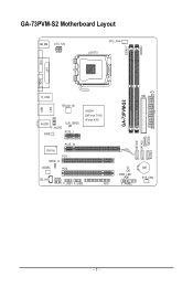
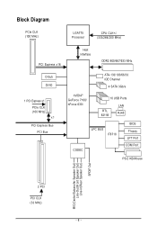
GA-73PVM-S2 Motherboard Layout KB_MS ATX_12V LGA775 CPU_FAN DDRII1 DDRII2 DVI LPT LAN VGA USB R_USB RTL8211B AUDIO F_AUDIO BIOS CLR_CMOS PCIE_1 nVIDIA® GeForce 7100/ nForce 630i PCIE_16 IT8718 PCI1 SPDIF_O CODEC PCI2 CD_IN COMA F_USB1 F_USB2 FDD ATX IDE GA-73PVM-S2 SATAII0 SATAII2 SATAII1 SATAII3 CI PWR_LED F_PANEL BAT SYS_FAN - 7 -
GA-73PVM-S2 Motherboard Layout KB_MS ATX_12V LGA775 CPU_FAN DDRII1 DDRII2 DVI LPT LAN VGA USB R_USB RTL8211B AUDIO F_AUDIO BIOS CLR_CMOS PCIE_1 nVIDIA® GeForce 7100/ nForce 630i PCIE_16 IT8718 PCI1 SPDIF_O CODEC PCI2 CD_IN COMA F_USB1 F_USB2 FDD ATX IDE GA-73PVM-S2 SATAII0 SATAII2 SATAII1 SATAII3 CI PWR_LED F_PANEL BAT SYS_FAN - 7 -
Manual
Page 8
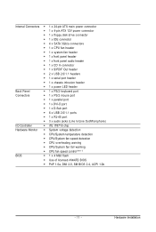
Block Diagram PCIe CLK (100 MHz) LGA775 Processor CPU CLK+/(333/266/200 MHz) PCI Express x16 Host Interface DDR2 800/667/533 MHz D-Sub DVI-D 1 PCI Express x1 PCIe CLK (100 MHz) x1 PCI Express Bus PCI Bus ATA-133/100/66/33 IDE Channel 4 SATA 3Gb/s nVIDIA® GeForce 7100/ nForce 630i 10 USB Ports RTL 8211B LAN RJ45 CODEC LPC BUS IT8718 BIOS Floppy LPT Port COM Port PS/2 KB/Mouse MIC(Center/Subwoofer Speaker Out) Line-Out(Front Speaker Out) Line-In(Rear Speaker Out) SPDIF Out 2 PCI PCI CLK (33 MHz) - 8 -
Block Diagram PCIe CLK (100 MHz) LGA775 Processor CPU CLK+/(333/266/200 MHz) PCI Express x16 Host Interface DDR2 800/667/533 MHz D-Sub DVI-D 1 PCI Express x1 PCIe CLK (100 MHz) x1 PCI Express Bus PCI Bus ATA-133/100/66/33 IDE Channel 4 SATA 3Gb/s nVIDIA® GeForce 7100/ nForce 630i 10 USB Ports RTL 8211B LAN RJ45 CODEC LPC BUS IT8718 BIOS Floppy LPT Port COM Port PS/2 KB/Mouse MIC(Center/Subwoofer Speaker Out) Line-Out(Front Speaker Out) Line-In(Rear Speaker Out) SPDIF Out 2 PCI PCI CLK (33 MHz) - 8 -
Manual
Page 11
.../System temperature detection Š CPU/System fan speed detection Š CPU overheating warning Š CPU/System fan fail warning Š CPU fan speed control (Note 1) BIOS Š 1 x 4 Mbit flash Š Use of licensed AWARD BIOS Š PnP 1.0a, DMI 2.0, SM BIOS 2.4, ACPI 1.0b - 11 - Hardware Installation
.../System temperature detection Š CPU/System fan speed detection Š CPU overheating warning Š CPU/System fan fail warning Š CPU fan speed control (Note 1) BIOS Š 1 x 4 Mbit flash Š Use of licensed AWARD BIOS Š PnP 1.0a, DMI 2.0, SM BIOS 2.4, ACPI 1.0b - 11 - Hardware Installation
Manual
Page 12
GA-73PVM-S2 Motherboard - 12 - Unique Features Bundled Software Operating System Form Factor Š Support for @BIOS Š Support for Download Center Š Support for Q-Flash Š Support for EasyTune (Note 2) Š Support for Xpress Install Š Support for Xpress Recovery2 Š Support for Virtual Dual BIOS Š Norton Internet Security (OEM version) Š Support for...
GA-73PVM-S2 Motherboard - 12 - Unique Features Bundled Software Operating System Form Factor Š Support for @BIOS Š Support for Download Center Š Support for Q-Flash Š Support for EasyTune (Note 2) Š Support for Xpress Install Š Support for Xpress Recovery2 Š Support for Virtual Dual BIOS Š Norton Internet Security (OEM version) Š Support for...

Manual
Page 17
... PCI Express x16 slot. • Removing the Card: Press the white latch at the end of the PCI Express x16 slot to make any required BIOS changes for your expansion card. • Always turn off the computer and unplug the power cord from the chassis back panel. 2. Align the card with...
... PCI Express x16 slot. • Removing the Card: Press the white latch at the end of the PCI Express x16 slot to make any required BIOS changes for your expansion card. • Always turn off the computer and unplug the power cord from the chassis back panel. 2. Align the card with...
Manual
Page 24
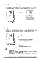
... Definition 1 MPD+ 1 2 MPD- 3 MPD- Gently remove the battery from the battery holder and wait for 5 seconds.) 3. Replace the battery. 4. GA-73PVM-S2 Motherboard - 24 - The LED keeps blinking when the system is operating. System Status LED S0 On S1 Blinking S3/S4/S5 Off 9) BAT (BATTERY)... must be handled in accordance with an equivalent one minute. (Or use a metal object like a screwdriver to keep the values (such as BIOS configurations, date, and time information) in the CMOS when the computer is in S3/S4 sleep state or powered off your computer and unplug the...
... Definition 1 MPD+ 1 2 MPD- 3 MPD- Gently remove the battery from the battery holder and wait for 5 seconds.) 3. Replace the battery. 4. GA-73PVM-S2 Motherboard - 24 - The LED keeps blinking when the system is operating. System Status LED S0 On S1 Blinking S3/S4/S5 Off 9) BAT (BATTERY)... must be handled in accordance with an equivalent one minute. (Or use a metal object like a screwdriver to keep the values (such as BIOS configurations, date, and time information) in the CMOS when the computer is in S3/S4 sleep state or powered off your computer and unplug the...
Manual
Page 25
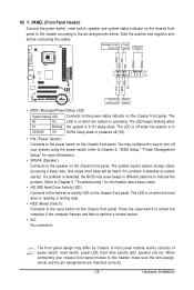
... heard if no problem is in different patterns to the pin assignments below. When connecting your system using the power switch (refer to Chapter 2, "BIOS Setup," "Power Management Setup," for information about beep codes. • HD (IDE Hard Drive Activity LED) Connects to the hard drive activity LED... status by chassis. If a problem is in S3/S4/S5 Off S3/S4 sleep state or powered off when the system is detected, the BIOS may differ by issuing a beep code. Note the positive and negative pins before connecting the cables. Hardware Installation The LED is off (S5). ...
... heard if no problem is in different patterns to the pin assignments below. When connecting your system using the power switch (refer to Chapter 2, "BIOS Setup," "Power Management Setup," for information about beep codes. • HD (IDE Hard Drive Activity LED) Connects to the hard drive activity LED... status by chassis. If a problem is in S3/S4/S5 Off S3/S4 sleep state or powered off when the system is detected, the BIOS may differ by issuing a beep code. Note the positive and negative pins before connecting the cables. Hardware Installation The LED is off (S5). ...
Manual
Page 28
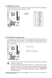
.... 1 2 3 4 5 6 7 8 9 10 Definition NDCDANSINA NSOUTA NDTRAGND NDSRANRTSANCTSANRIANo Pin 16) CLR_CMOS (Clearing CMOS Jumper) Use this jumper to factory defaults. GA-73PVM-S2 Motherboard - 28 - To clear the CMOS values, place a jumper cap on your computer and unplug the power cord from the jumper. Open: Normal Short: Clear...two pins to temporarily short the two pins or use a metal object like a screwdriver to Chapter 2, "BIOS Setup," for a few seconds. date information and BIOS configurations) and reset the CMOS values to clear the CMOS values (e.g. Failure to do so may cause ...
.... 1 2 3 4 5 6 7 8 9 10 Definition NDCDANSINA NSOUTA NDTRAGND NDSRANRTSANCTSANRIANo Pin 16) CLR_CMOS (Clearing CMOS Jumper) Use this jumper to factory defaults. GA-73PVM-S2 Motherboard - 28 - To clear the CMOS values, place a jumper cap on your computer and unplug the power cord from the jumper. Open: Normal Short: Clear...two pins to temporarily short the two pins or use a metal object like a screwdriver to Chapter 2, "BIOS Setup," for a few seconds. date information and BIOS configurations) and reset the CMOS values to clear the CMOS values (e.g. Failure to do so may cause ...
Manual
Page 31
...) during the POST when the power is turned off, the battery on . Inadequate BIOS flashing may result in the main menu of BIOS, it with caution. To upgrade the BIOS, use either the GIGABYTE Q-Flash or @BIOS utility. • Q-Flash allows the user to quickly and easily upgrade or back ...up BIOS without entering the operating system. • @BIOS is potentially risky, if you do it...
...) during the POST when the power is turned off, the battery on . Inadequate BIOS flashing may result in the main menu of BIOS, it with caution. To upgrade the BIOS, use either the GIGABYTE Q-Flash or @BIOS utility. • Q-Flash allows the user to quickly and easily upgrade or back ...up BIOS without entering the operating system. • @BIOS is potentially risky, if you do it...
Manual
Page 32
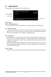
...setting as needed. : Q-Flash Press the key to access the Q-Flash utility directly without entering BIOS Setup. The system will still be used for one time only. GA-73PVM-S2 F1a . . . . : BIOS Setup/Q-Flash : XpressRecovery2 : Boot Menu : Qflash 11/21/2007-NF73-6A61NG05C-00 Function Keys ...Function Keys: : BIOS Setup/Q-Flash Press the key to enter BIOS Setup or to access the Q-Flash utility in BIOS Setup. : Xpress Recovery2 If...
...setting as needed. : Q-Flash Press the key to access the Q-Flash utility directly without entering BIOS Setup. The system will still be used for one time only. GA-73PVM-S2 F1a . . . . : BIOS Setup/Q-Flash : XpressRecovery2 : Boot Menu : Qflash 11/21/2007-NF73-6A61NG05C-00 Function Keys ...Function Keys: : BIOS Setup/Q-Flash Press the key to enter BIOS Setup or to access the Q-Flash utility in BIOS Setup. : Xpress Recovery2 If...
Manual
Page 33
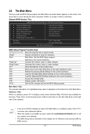
...select the Load Optimized Defaults item to set your system to its defaults. • The BIOS Setup menus described in this chapter are for reference only and may differ by BIOS version. - 33 - BIOS Setup Program Function Keys Move the selection bar to select an item Execute command or enter the...) of function keys available for the current submenus Access the Q-Flash utility Display system information Save all the changes and exit the BIOS Setup program Main Menu Help The onscreen description of a highlighted setup option is not stable as shown below) appears on the screen...
...select the Load Optimized Defaults item to set your system to its defaults. • The BIOS Setup menus described in this chapter are for reference only and may differ by BIOS version. - 33 - BIOS Setup Program Function Keys Move the selection bar to select an item Execute command or enter the...) of function keys available for the current submenus Access the Q-Flash utility Display system information Save all the changes and exit the BIOS Setup program Main Menu Help The onscreen description of a highlighted setup option is not stable as shown below) appears on the screen...
Manual
Page 34
... peripheral devices, such as IDE, SATA, USB, integrated audio, and integrated LAN, etc. „ Power Management Setup Use this task.) GA-73PVM-S2 Motherboard - 34 - Pressing to the confirmation message will exit BIOS Setup. (Pressing can also carry out this task.) „ Exit Without Saving Abandon all the power-saving functions. „ PnP/PCI...
... peripheral devices, such as IDE, SATA, USB, integrated audio, and integrated LAN, etc. „ Power Management Setup Use this task.) GA-73PVM-S2 Motherboard - 34 - Pressing to the confirmation message will exit BIOS Setup. (Pressing can also carry out this task.) „ Exit Without Saving Abandon all the power-saving functions. „ PnP/PCI...
Manual
Page 35
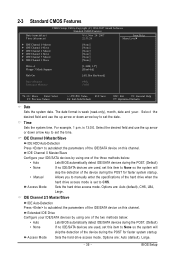
... Sets the system date. IDE Channel 0 Master/Slave Configure your IDE/SATA devices by using one of the three methods below : • Auto Lets BIOS automatically detect IDE/SATA devices during the POST. (Default) • None If no IDE/SATA devices are used , set this item to None so ...faster system startup. Extended IDE Drive Configure your IDE/SATA devices by using one of the two methods below : • Auto • None Lets BIOS automatically detect IDE/SATA devices during the POST. (Default) If no IDE/SATA devices are used , set this item to None so the system will...
... Sets the system date. IDE Channel 0 Master/Slave Configure your IDE/SATA devices by using one of the three methods below : • Auto Lets BIOS automatically detect IDE/SATA devices during the POST. (Default) • None If no IDE/SATA devices are used , set this item to None so ...faster system startup. Extended IDE Drive Configure your IDE/SATA devices by using one of the two methods below : • Auto • None Lets BIOS automatically detect IDE/SATA devices during the POST. (Default) If no IDE/SATA devices are used , set this item to None so the system will...
Manual
Page 36
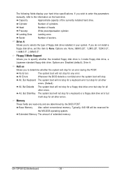
...Capacity Approximate capacity of heads. Head Number of the currently installed hard drive. Sector Number of cylinders. All Errors Whenever the BIOS detects a non-fatal error the system boot will stop for any error. Base Memory Also called conventional memory. No Errors ... All, But Diskette The system boot will not stop . Extended Memory The amount of floppy disk drive installed in your hard drive specifications. GA-73PVM-S2 Motherboard - 36 - The following fields display your system. Drive A Allows you to specify whether the installed floppy disk drive is 3-mode...
...Capacity Approximate capacity of heads. Head Number of the currently installed hard drive. Sector Number of cylinders. All Errors Whenever the BIOS detects a non-fatal error the system boot will stop for any error. Base Memory Also called conventional memory. No Errors ... All, But Diskette The system boot will not stop . Extended Memory The amount of floppy disk drive installed in your hard drive specifications. GA-73PVM-S2 Motherboard - 36 - The following fields display your system. Drive A Allows you to specify whether the installed floppy disk drive is 3-mode...
Manual
Page 37
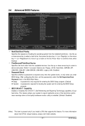
...to move it up or down on the list. Password Check Specifies whether a password is required for booting the system and for entering the BIOS Setup program. (Default) System A password is required every time the system boots, or only when you install a CPU that supports this menu..., CDROM, ZIP, USB-FDD, USB-ZIP, USB-CDROM, USB-HDD, Legacy LAN, Disabled. Setup A password is only required for entering the BIOS Setup program. HDD S.M.A.R.T. Capability Enables or disables the S.M.A.R.T. (Self Monitoring and Reporting Technology) capability of your system to report read/write errors of the...
...to move it up or down on the list. Password Check Specifies whether a password is required for booting the system and for entering the BIOS Setup program. (Default) System A password is required every time the system boots, or only when you install a CPU that supports this menu..., CDROM, ZIP, USB-FDD, USB-ZIP, USB-CDROM, USB-HDD, Legacy LAN, Disabled. Setup A password is only required for entering the BIOS Setup program. HDD S.M.A.R.T. Capability Enables or disables the S.M.A.R.T. (Self Monitoring and Reporting Technology) capability of your system to report read/write errors of the...

Manual
Page 39
... the first display. - 39 - MS-DOS, for example, will use only this memory for the onboard graphics controller. Options are: 64M, 128M (default), 256M, Disabled. BIOS Setup PEG Sets PCI Express graphics card as the first display. Frame Buffer Size Frame buffer size is the total amount of the monitor display...
... the first display. - 39 - MS-DOS, for example, will use only this memory for the onboard graphics controller. Options are: 64M, 128M (default), 256M, Disabled. BIOS Setup PEG Sets PCI Express graphics card as the first display. Frame Buffer Size Frame buffer size is the total amount of the monitor display...

Manual
Page 41
USB Memory Type Specifies the type of using the onboard LAN, set to Disabled. BIOS Setup Advanced Host Controller Interface (AHCI) is set to install a 3rd party add-in audio card instead of memory allocated for the fourth SATA 3Gb/s ...
USB Memory Type Specifies the type of using the onboard LAN, set to Disabled. BIOS Setup Advanced Host Controller Interface (AHCI) is set to install a 3rd party add-in audio card instead of memory allocated for the fourth SATA 3Gb/s ...


