Manual
Page 1
Table of Contents Configuring SATA Hard Drive(s) (Controller: VIA VT8237/VT8237R 2 (1) Installing SATA hard drive(s) in your computer 2 (2) Configuring SATA controller mode and boot sequence in BIOS Setup 3 (3) Configuring RAID set in RAID BIOS 5 (4) Making a SATA Driver Disk 10 (5) Installing SATA controller driver during OS installation 12
Table of Contents Configuring SATA Hard Drive(s) (Controller: VIA VT8237/VT8237R 2 (1) Installing SATA hard drive(s) in your computer 2 (2) Configuring SATA controller mode and boot sequence in BIOS Setup 3 (3) Configuring RAID set in RAID BIOS 5 (4) Making a SATA Driver Disk 10 (5) Installing SATA controller driver during OS installation 12
Manual
Page 2
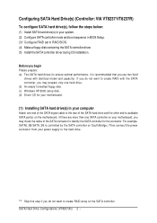
... connect the power connector from your power supply to the hard drive. SATA Hard Drive Configurations (VT8237(R)) 2 - Ác Configuring SATA Hard Drive(s) (Controller: VIA VT8237/VT8237R) Åé To configure SATA hard drive(s), follow the steps below: ¤¤ (1) Install SATA hard drive(s) in your system. ¤å (2) Configure SATA controller mode and boot sequence in BIOS Setup. (3)* Configure RAID set in your computer Attach one end of the SATA signal cable to the rear of the SATA connector to identify the SATA controller for your motherboard, you use two hard...
... connect the power connector from your power supply to the hard drive. SATA Hard Drive Configurations (VT8237(R)) 2 - Ác Configuring SATA Hard Drive(s) (Controller: VIA VT8237/VT8237R) Åé To configure SATA hard drive(s), follow the steps below: ¤¤ (1) Install SATA hard drive(s) in your system. ¤å (2) Configure SATA controller mode and boot sequence in BIOS Setup. (3)* Configure RAID set in your computer Attach one end of the SATA signal cable to the rear of the SATA connector to identify the SATA controller for your motherboard, you use two hard...
Manual
Page 3
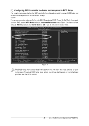
... POST (Power-On Self Test). CMOS Setup Utility-Copyright (C) 1984-2004 Award Software Integrated Peripherals IDE DMA transfer access OnChip IDE Channel 0 OnChip IDE Channel 1 OnChip Serial ATA SATA Mode AC97 Audio VIA Onboard LAN USB 1.1 Controller USB 2.0 Controller USB Keyboard Support USB Mouse Support Onboard H/W LAN Onboard H/W 1394 Onboard H/W Serial ATA Serial ATA Function GigaBit LAN Boot ROM On-Chip LAN Boot ROM Onboard Serial Port 1 Onboard Serial Port 2 [Enabled] [Enabled] [Enabled] [Enabled] [RAID] [Auto] [Enabled] [Enabled] [Enabled] [Disabled] [Disabled] [Enabled] [Enabled...
... POST (Power-On Self Test). CMOS Setup Utility-Copyright (C) 1984-2004 Award Software Integrated Peripherals IDE DMA transfer access OnChip IDE Channel 0 OnChip IDE Channel 1 OnChip Serial ATA SATA Mode AC97 Audio VIA Onboard LAN USB 1.1 Controller USB 2.0 Controller USB Keyboard Support USB Mouse Support Onboard H/W LAN Onboard H/W 1394 Onboard H/W Serial ATA Serial ATA Function GigaBit LAN Boot ROM On-Chip LAN Boot ROM Onboard Serial Port 1 Onboard Serial Port 2 [Enabled] [Enabled] [Enabled] [Enabled] [RAID] [Auto] [Enabled] [Enabled] [Enabled] [Disabled] [Disabled] [Enabled] [Enabled...
Manual
Page 4
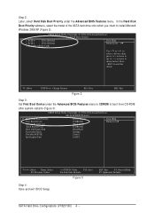
... Menu Level} Second Boot Device [Hard Disk] Third Boot Device [CDROM] Boot Up Floopy Seek Password Check Flexible AGP 8X [Disabled] [Setup] [Auto] Init Display First [AGP] higf: Move Enter: Select F5: Previous Values Step 4: Save and exit BIOS Setup. +/-/PU/PD: Value F10: Save F6: Fail-Safe Defaults Figure 3 ESC: Exit F1: General Help F7: Optimized Defaults SATA Hard Drive Configurations (VT8237(R)) 4 - CMOS Setup Utility-Copyright (C) 1984-2004 Award Software Hard Disk Boot Priority 1. Bootable Add-in Cards Item Help Menu Level }} Use...
... Menu Level} Second Boot Device [Hard Disk] Third Boot Device [CDROM] Boot Up Floopy Seek Password Check Flexible AGP 8X [Disabled] [Setup] [Auto] Init Display First [AGP] higf: Move Enter: Select F5: Previous Values Step 4: Save and exit BIOS Setup. +/-/PU/PD: Value F10: Save F6: Fail-Safe Defaults Figure 3 ESC: Exit F1: General Help F7: Optimized Defaults SATA Hard Drive Configurations (VT8237(R)) 4 - CMOS Setup Utility-Copyright (C) 1984-2004 Award Software Hard Disk Boot Priority 1. Bootable Add-in Cards Item Help Menu Level }} Use...
Manual
Page 10
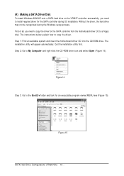
... insert the motherboard driver CD into the CD-ROM drive. Step 2: Go to copy the driver. The instructions below explain how to My Computer and right-click the CD-ROM drive icon and select Open (Figure 14). Ác (4) Making a SATA Driver Disk Åé To install Windows 2000/XP onto a SATA hard drive on the VT8237 controller successfully, you need to install required driver for the SATA controller during the Windows setup process...
... insert the motherboard driver CD into the CD-ROM drive. Step 2: Go to copy the driver. The instructions below explain how to My Computer and right-click the CD-ROM drive icon and select Open (Figure 14). Ác (4) Making a SATA Driver Disk Åé To install Windows 2000/XP onto a SATA hard drive on the VT8237 controller successfully, you need to install required driver for the SATA controller during the Windows setup process...

Manual
Page 12
... have prepared the SATA driver disk and configured BIOS settings, you need to install a 3rd party SCSI or RAID driver. The following mass storage devices(s) * To specify additional SCSI adapters, CD-ROM drives, or special disk controllers for use with the SATA driver. After pressing F6, there will load support for the following is an example of some files being loaded before you do not want to manually specify an adapter. Windows Setup Press F6...
... have prepared the SATA driver disk and configured BIOS settings, you need to install a 3rd party SCSI or RAID driver. The following mass storage devices(s) * To specify additional SCSI adapters, CD-ROM drives, or special disk controllers for use with the SATA driver. After pressing F6, there will load support for the following is an example of some files being loaded before you do not want to manually specify an adapter. Windows Setup Press F6...

Manual
Page 14
... hard drive to a RAID array, the RAID driver will not have installed the SATA controller driver successfully. This port of the Setup program prepares Microsoft(R) Windows (R) XP to be installed under Windows once for that hard drive. It indicates that , the driver will have to Setup. After that you should see a screen as below. You can proceed with the Windows 2000/XP installation. To repair a Windows XP installation using Recovery Console, press R. To quit Setup without installing Windows XP...
... hard drive to a RAID array, the RAID driver will not have installed the SATA controller driver successfully. This port of the Setup program prepares Microsoft(R) Windows (R) XP to be installed under Windows once for that hard drive. It indicates that , the driver will have to Setup. After that you should see a screen as below. You can proceed with the Windows 2000/XP installation. To repair a Windows XP installation using Recovery Console, press R. To quit Setup without installing Windows XP...
User Manual
Page 4
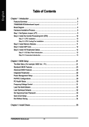
... 5: Install I/O Peripherals Cables 12 Step 5-1: I/O Back Panel Introduction 12 Step 5-2: Connectors Introduction 13 Chapter 2 BIOS Setup 21 The Main Menu (For example: BIOS Ver. : F1 21 Standard CMOS Features ...23 Advanced BIOS Features ...25 Integrated Peripherals ...26 Power Management Setup 28 PnP/PCI Configurations ...29 PC Health Status ...30 Frequency/Voltage Control 31 Load Fail-Safe Defaults ...32 Load Optimized Defaults ...32 Set Supervisor/User Password 33 Save & Exit Setup ...34 Exit Without Saving ...34 Chapter 3 Install Drivers 35 7VM400AM-RZ Motherboard...
... 5: Install I/O Peripherals Cables 12 Step 5-1: I/O Back Panel Introduction 12 Step 5-2: Connectors Introduction 13 Chapter 2 BIOS Setup 21 The Main Menu (For example: BIOS Ver. : F1 21 Standard CMOS Features ...23 Advanced BIOS Features ...25 Integrated Peripherals ...26 Power Management Setup 28 PnP/PCI Configurations ...29 PC Health Status ...30 Frequency/Voltage Control 31 Load Fail-Safe Defaults ...32 Load Optimized Defaults ...32 Set Supervisor/User Password 33 Save & Exit Setup ...34 Exit Without Saving ...34 Chapter 3 Install Drivers 35 7VM400AM-RZ Motherboard...

User Manual
Page 5
... CPU Chipset Memory Slots On-Board IDE On-Board Floppy On-Board Serial ATA On-Board Peripherals On-Board VGA On-Board LAN On-Board Sound On-Board SATA RAID y Socket A for AMD Athlon™ XP / Athlon™ / Duron™ processor y 200/266/333/400MHz FSB y Supports 1.4GHz and faster y Northbridge : VIA KM400A y Southbridge : VIA 8237 y 2 184-pin DDR DIMM sockets, supports up to 2GB DRAM (Max) y Supports DDR400/DDR333 DIMM y Supports only 2.5V DDR SDRAM y 1 AGP slot supports 8X/4X(1.5V) mode y 3 PCI slots support 33MHz & PCI...
... CPU Chipset Memory Slots On-Board IDE On-Board Floppy On-Board Serial ATA On-Board Peripherals On-Board VGA On-Board LAN On-Board Sound On-Board SATA RAID y Socket A for AMD Athlon™ XP / Athlon™ / Duron™ processor y 200/266/333/400MHz FSB y Supports 1.4GHz and faster y Northbridge : VIA KM400A y Southbridge : VIA 8237 y 2 184-pin DDR DIMM sockets, supports up to 2GB DRAM (Max) y Supports DDR400/DDR333 DIMM y Supports only 2.5V DDR SDRAM y 1 AGP slot supports 8X/4X(1.5V) mode y 3 PCI slots support 33MHz & PCI...
User Manual
Page 10
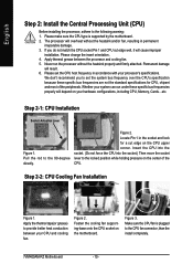
... the CPU fan connector, than the install completely. 7VM400AM-RZ Motherboard - 10 - Insert the CPU into the socket. (Do not force the CPU into the socket.) Then move the socket lever to set the CPU host frequency in the socket and look for CPU, chipset and most of the CPU. Figure 2. Figure 3. Please change the insert orientation. 4. Apply thermal grease between your system can run the processor without the heatsink and/or fan...
... the CPU fan connector, than the install completely. 7VM400AM-RZ Motherboard - 10 - Insert the CPU into the socket. (Do not force the CPU into the socket.) Then move the socket lever to set the CPU host frequency in the socket and look for CPU, chipset and most of the CPU. Figure 2. Figure 3. Please change the insert orientation. 4. Apply thermal grease between your system can run the processor without the heatsink and/or fan...
User Manual
Page 15
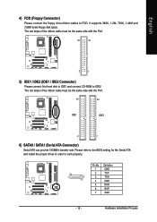
... floppy disk types. Pin No. The red stripe of the ribbon cable must be the same side with the Pin1. 40 39 IDE1 IDE2 2 1 6) SATA0 / SATA1 (Serial ATA Connector) Serial ATA can provide 150MB/s transfer rate. English 4) FDD (Floppy Connector) Please connect the floppy drive ribbon cables to work properly. Please refer to the BIOS setting for the Serial ATA and install the proper driver in order to FDD. Hardware Installation...
... floppy disk types. Pin No. The red stripe of the ribbon cable must be the same side with the Pin1. 40 39 IDE1 IDE2 2 1 6) SATA0 / SATA1 (Serial ATA Connector) Serial ATA can provide 150MB/s transfer rate. English 4) FDD (Floppy Connector) Please connect the floppy drive ribbon cables to work properly. Please refer to the BIOS setting for the Serial ATA and install the proper driver in order to FDD. Hardware Installation...

User Manual
Page 16
...connect with the system power indicator to the pin assignment below. Message LED/ Power/ Power Sleep LED Switch Speaker Connector MSG+ MSG- Pin No. RESRES+ NC HD (IDE Hard Disk Active LED) SPK (Speaker Connector) RES (Reset Switch) PW (Power Switch) MSG (Message LED/ Power/ Sleep LED) NC Reset Switch IDE Hard Disk Active LED Pin 1: LED anode(+) Pin 2: LED cathode(-) Pin 1: VCC(+) Pin 2- Pin 3: NC Pin 4: Data(-) Open: Normal Operation Close: Reset Hardware System Open: Normal Operation Close: Power On/Off Pin 1: LED anode(+) Pin 2: LED cathode(-) NC 7VM400AM-RZ Motherboard...
...connect with the system power indicator to the pin assignment below. Message LED/ Power/ Power Sleep LED Switch Speaker Connector MSG+ MSG- Pin No. RESRES+ NC HD (IDE Hard Disk Active LED) SPK (Speaker Connector) RES (Reset Switch) PW (Power Switch) MSG (Message LED/ Power/ Sleep LED) NC Reset Switch IDE Hard Disk Active LED Pin 1: LED anode(+) Pin 2: LED cathode(-) Pin 1: VCC(+) Pin 2- Pin 3: NC Pin 4: Data(-) Open: Normal Operation Close: Reset Hardware System Open: Normal Operation Close: Power On/Off Pin 1: LED anode(+) Pin 2: LED cathode(-) NC 7VM400AM-RZ Motherboard...

User Manual
Page 17
... digital input function. English 9) F_AUDIO (Front Audio Connector) If you want to use Front Audio connector, you are buying support front audio connector, please contact your dealer. For optional SPDIF cable, please contact your chassis must remove 5-6, 9-10 Jumper. To find out if the chassis you must have the alternative of using rear audio connector to play sound. In order to utilize the front audio header, your local dealer. Definition 12 1 VCC...
... digital input function. English 9) F_AUDIO (Front Audio Connector) If you want to use Front Audio connector, you are buying support front audio connector, please contact your dealer. For optional SPDIF cable, please contact your chassis must remove 5-6, 9-10 Jumper. To find out if the chassis you must have the alternative of using rear audio connector to play sound. In order to utilize the front audio header, your local dealer. Definition 12 1 VCC...

User Manual
Page 19
..." to enable or disable the "case open" item in BIOS if the system case begin remove. Short: Clear CMOS 1 Open: Normal 1 17) CI (Chassis Intrusion, Case Open) This 2-pin connector allows your local dealer. 2 10 1 9 Pin No. 1 2 3 4 5 6 7 8 9 10 Definition Power Power USB DxUSB DyUSB Dx+ USB Dy+ GND GND No Pin NC 16) CLR_CMOS (Clear CMOS) You may clear the CMOS data to work or even damage it. To clear CMOS, temporarily short 1-2 pin. Hardware Installation Process For optional front USB cable...
..." to enable or disable the "case open" item in BIOS if the system case begin remove. Short: Clear CMOS 1 Open: Normal 1 17) CI (Chassis Intrusion, Case Open) This 2-pin connector allows your local dealer. 2 10 1 9 Pin No. 1 2 3 4 5 6 7 8 9 10 Definition Power Power USB DxUSB DyUSB Dx+ USB Dy+ GND GND No Pin NC 16) CLR_CMOS (Clear CMOS) You may clear the CMOS data to work or even damage it. To clear CMOS, temporarily short 1-2 pin. Hardware Installation Process For optional front USB cable...
User Manual
Page 22
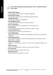
... features. • PnP/PCI Configuration This setup page includes all CM OS v alue changes and ex it s etup. • Exit Without S aving Abandon all the configurations of PCI & PnP ISA resources. • PC Health Status This setup page is the Sy stem auto detect Temperature, v oltage, fan, s peed. • Frequency/Voltage Control This setup page is control CPU clock and frequency ratio. • Load Fail-Safe Defaults Fail-Safe Defaults indicates the v alue...
... features. • PnP/PCI Configuration This setup page includes all CM OS v alue changes and ex it s etup. • Exit Without S aving Abandon all the configurations of PCI & PnP ISA resources. • PC Health Status This setup page is the Sy stem auto detect Temperature, v oltage, fan, s peed. • Frequency/Voltage Control This setup page is control CPU clock and frequency ratio. • Load Fail-Safe Defaults Fail-Safe Defaults indicates the v alue...
User Manual
Page 23
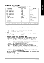
...:00. You can manually input the correct settings IDE C hannel 2/ 3 Master IDE Dev ic e Setup. BIOS Setup Day The day , from 1 to automatic ally detec t IDE dev ices during POST(default) None Selec t this to Sat, determined by the BIOS and is , , , . is calculated base on this option for faster sy s tem start up . Access Mode Use this if no IDE dev ices are used and the sy...
...:00. You can manually input the correct settings IDE C hannel 2/ 3 Master IDE Dev ic e Setup. BIOS Setup Day The day , from 1 to automatic ally detec t IDE dev ices during POST(default) None Selec t this to Sat, determined by the BIOS and is , , , . is calculated base on this option for faster sy s tem start up . Access Mode Use this if no IDE dev ices are used and the sy...
User Manual
Page 26
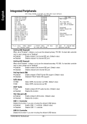
... Exit F1: General Help F7: Optimiz ed Defa ults OnChi p IDE Channel0 When set at "Enabled", it allow s y ou to use the onboard primary PCI IDE. SATA Mode RAID IDE Selec t SATA chip function as RAID. (Default v alue) Selec t SATA c hip func tion as IDE. USB 1.1 Controller Disable this function if y ou are not using the onboard USB feature. 7VM400AM-RZ Motherboard - 26 - Enab led Enable onboard 1st channel IDE port. (Default v alue) Disa bled Disable onboard 1st channel IDE port. Enab led Enable USB 1. 1 controller. (Default v alue) Disa bled Disable USB 1. 1 controller.
... Exit F1: General Help F7: Optimiz ed Defa ults OnChi p IDE Channel0 When set at "Enabled", it allow s y ou to use the onboard primary PCI IDE. SATA Mode RAID IDE Selec t SATA chip function as RAID. (Default v alue) Selec t SATA c hip func tion as IDE. USB 1.1 Controller Disable this function if y ou are not using the onboard USB feature. 7VM400AM-RZ Motherboard - 26 - Enab led Enable onboard 1st channel IDE port. (Default v alue) Disa bled Disable onboard 1st channel IDE port. Enab led Enable USB 1. 1 controller. (Default v alue) Disa bled Disable USB 1. 1 controller.
User Manual
Page 28
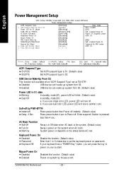
... P ower On Disa bled Enab led Disabled this function. (Default v alue) Pass w ord Enter from S3. Soft-off by mouse ev ent. 7VM400AM-RZ Motherboard - 28 - If y ou use dual color LED, pow er LED w ill ture to pow er on sy stem by PWR-BTTN Instan t-off Press pow er button then Pow er off . English Power Management Setup CMOS Setup Ut ility-Co pyright...
... P ower On Disa bled Enab led Disabled this function. (Default v alue) Pass w ord Enter from S3. Soft-off by mouse ev ent. 7VM400AM-RZ Motherboard - 28 - If y ou use dual color LED, pow er LED w ill ture to pow er on sy stem by PWR-BTTN Instan t-off Press pow er button then Pow er off . English Power Management Setup CMOS Setup Ut ility-Co pyright...
User Manual
Page 30
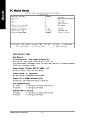
If the case hav e been opened, "Case Opened" w ill show "No". Current System/ CPU Temperature Detec t sy stem /CPU temperature automatic ally . SYSTEM FAN Fail Warning Disa bled Fan w arning function disable. (Default v alue) Enab led Fan w arning function enable. 7VM400AM-RZ Motherboard - 30 - CPU FAN Fail Warning Disa bled Fan w arning function disable. (Default v alue) Enab led Fan w arning function enable. English PC Health Status CMOS Setup Utility-Copyright (C) 1984-2004 Award Software PC Health Status Rese t Case Open St...
If the case hav e been opened, "Case Opened" w ill show "No". Current System/ CPU Temperature Detec t sy stem /CPU temperature automatic ally . SYSTEM FAN Fail Warning Disa bled Fan w arning function disable. (Default v alue) Enab led Fan w arning function enable. 7VM400AM-RZ Motherboard - 30 - CPU FAN Fail Warning Disa bled Fan w arning function disable. (Default v alue) Enab led Fan w arning function enable. English PC Health Status CMOS Setup Utility-Copyright (C) 1984-2004 Award Software PC Health Status Rese t Case Open St...
User Manual
Page 36
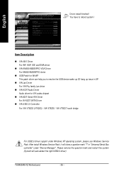
... ! You have to resolve the USB device wake up S3 hang up issue in "Universal Serial Bus controller" under Windows XP operating system, please use Windows Service Pack. After install Windows Service Pack, it will auto-detect the right USB2.0 driver). 7VM400AM-RZ Motherboard - 36 - in XP n VIA Lan Driver For VIA Phy family Lan driver n VIA AC97 Audio Driver Audio driver for VIA codec chipset n VIA 8237 Serial ATA Driver For VIA 8237 SATA Driver n VIA USB 2.0 Controller For VIA VT8233 (VT6203...
... ! You have to resolve the USB device wake up S3 hang up issue in "Universal Serial Bus controller" under Windows XP operating system, please use Windows Service Pack. After install Windows Service Pack, it will auto-detect the right USB2.0 driver). 7VM400AM-RZ Motherboard - 36 - in XP n VIA Lan Driver For VIA Phy family Lan driver n VIA AC97 Audio Driver Audio driver for VIA codec chipset n VIA 8237 Serial ATA Driver For VIA 8237 SATA Driver n VIA USB 2.0 Controller For VIA VT8233 (VT6203...


